Week 10 - Project 6 - Master Section Development
Aim- Is to design B-Pillar lower using Master section.
Objectives:-
- Create closed body of the Given B pillar Lower.
- Crete tooling axis and follow design rules.
- Follow the Master section to create flange.
- Follow the master section for thickness and to create the Closed volume.
- Follow master section to create Attachment features.
Content:-
step1- Creating flange following the master section.
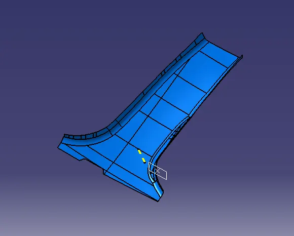 A-surface of B-Pillar lower.
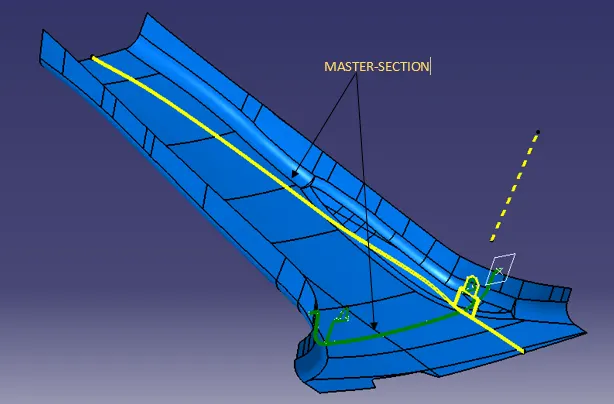 Followed the master section to create the flange.
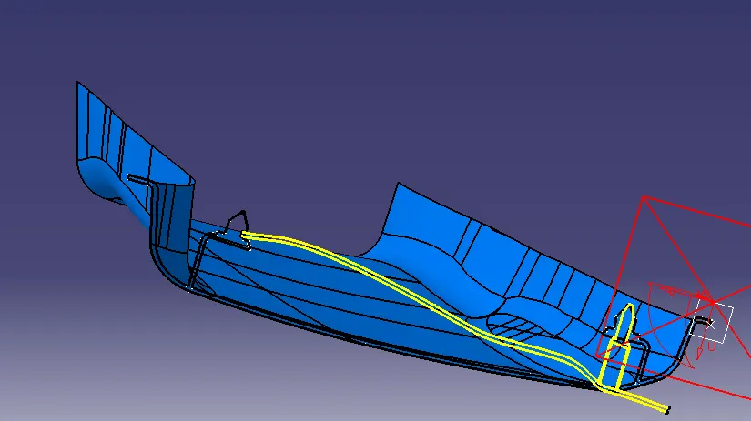
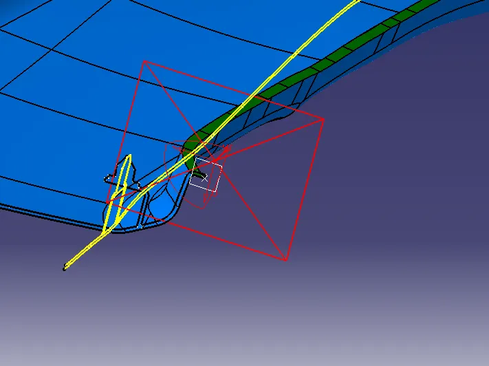
Flange is created by using sweep option tree structure of creating the flange 1 and flange 2 is shown below:-
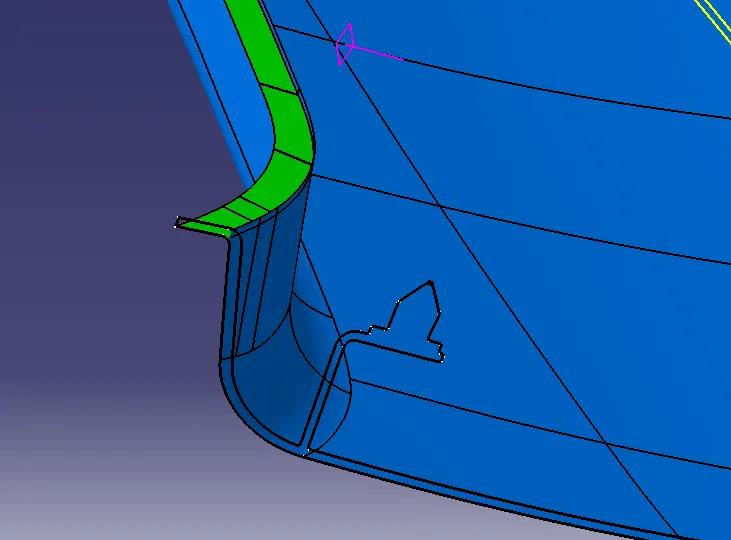 Flange-1
 Flange-2
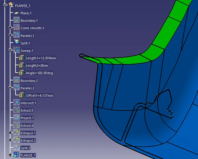 Tree-structure of Flange-1
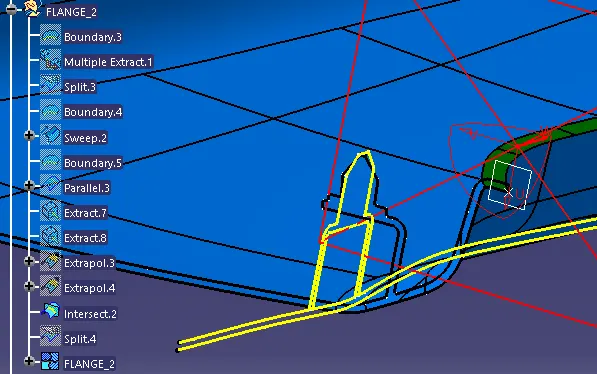 Tree-structure of Flange-2.
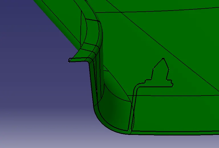
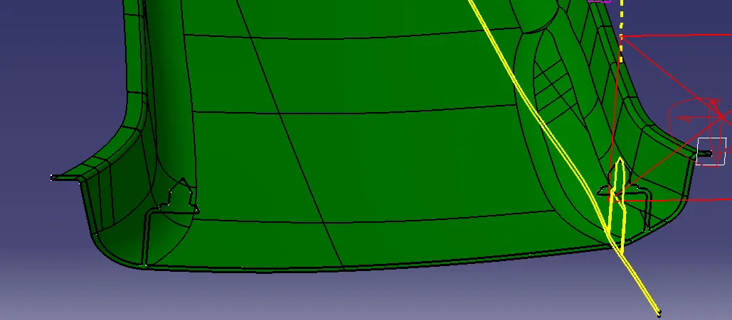
Above picture shows the final modified class-A surface after creating flanges.
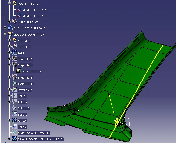
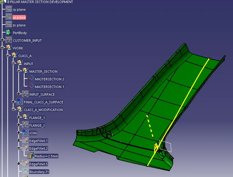
Above picture shows the tree structure of Class-A surface.
Step2 - Creating Tooling axis for B-Pillar Lower.
Tooling axis-The Tooling Direction is basically the direction that the mold pulls apart. The mold is built in two separate pieces, basically,one piece is Cavity side and the other one is Core side.
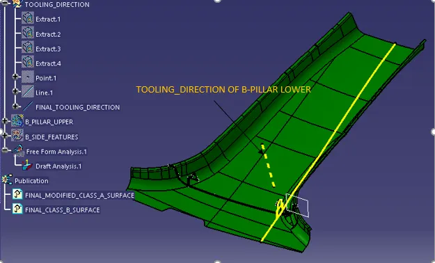
Above picture shows the tooling axis of the given part.
Step3 - Creating closed body of B-pillar Lower.
For creating closed body of the part a tree-structure is followed:-
- First modified the class-A surface as per master section that is by creating flange
- Second offset the class-A surface by 2mm to create the B-surface and this 2mm distance is measured from the master section,surfaces which are not getting offset can be filled by using multisection command,blend and fill command.
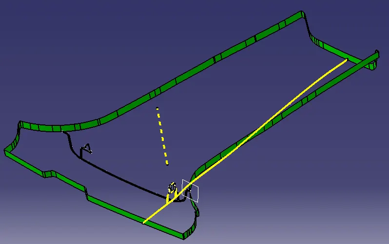
- Third after creating B-surface,C-surface is created.
- Fourth after creating C-surface ,extra surfaces are trimed and joined to create the closed-volume.
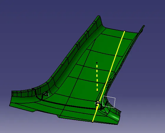 Modified Class-A surface that is by adding flange as per master section.
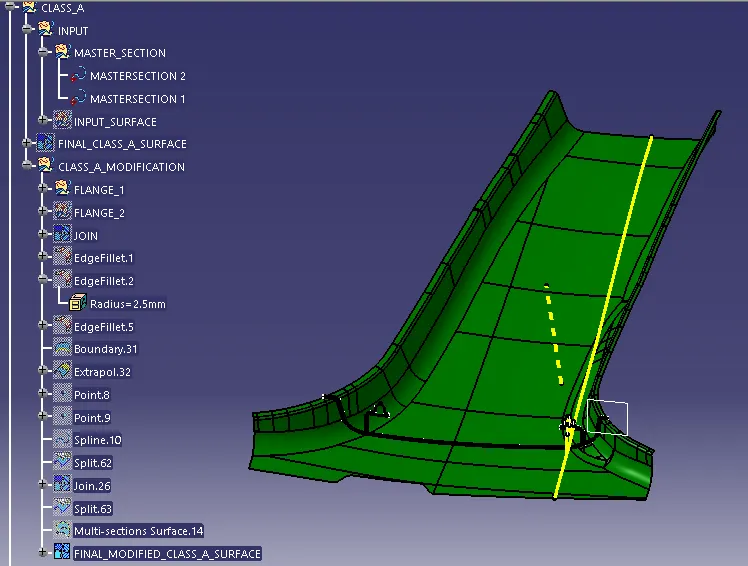 Tree-structure of Class-A surface.
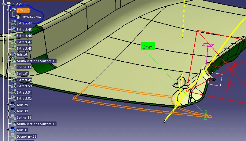
A-Surface is offseted by 2mm for creating B-Surface and this value is calculated from the master section as shown in the above picture.
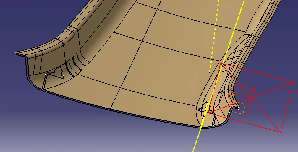 Cross-section view of B-Surface.
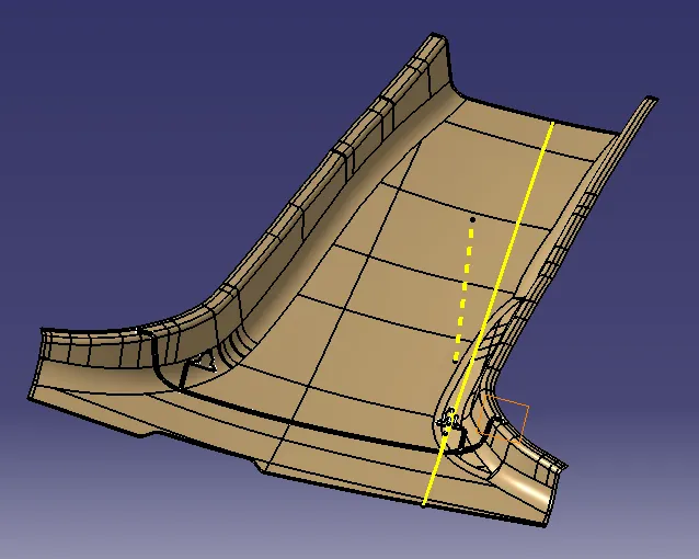 Final class-B surface.
Tree-structure of Class-B surface is shown below:-
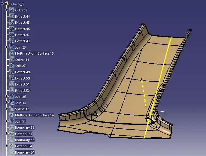
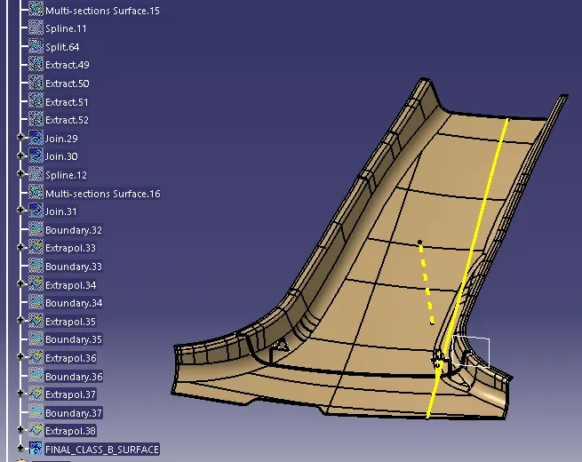
Tree-structure of class-C surface is shown below:-
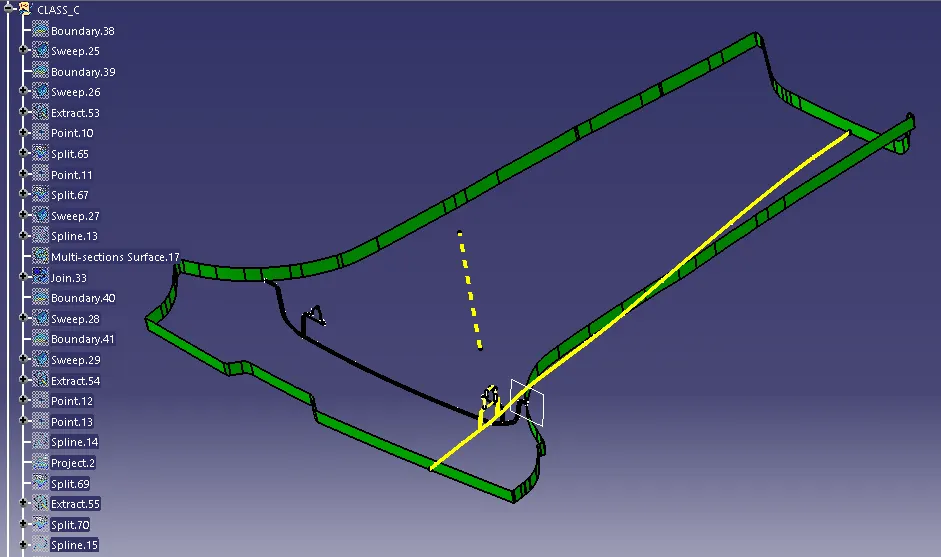
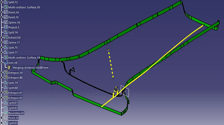
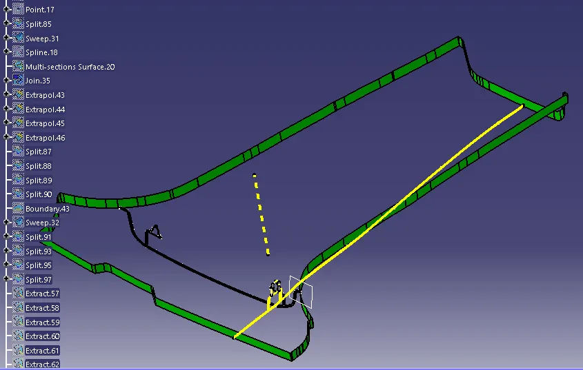
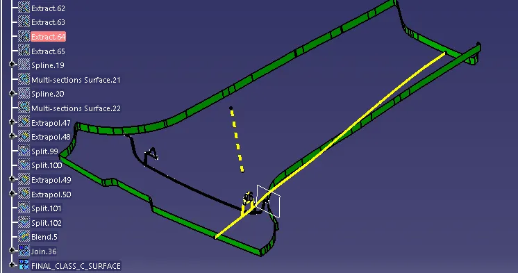
Final class-C surface is shown below:-
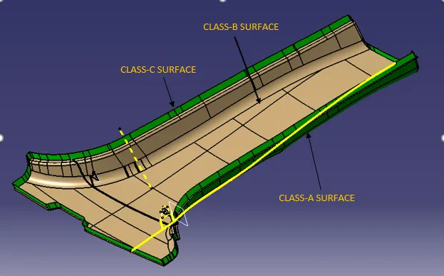
Final class-A,class-B and class-C surface is shown below:-
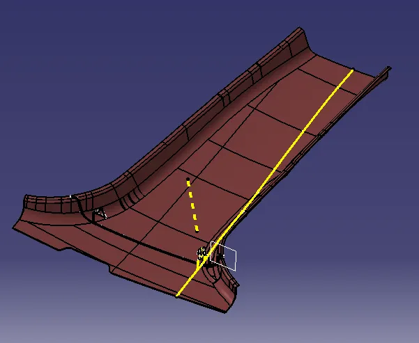
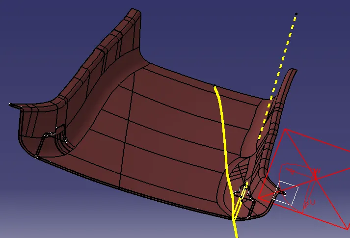
Above picture shows the colsed volume of the model and section view.
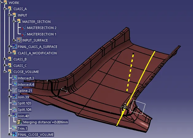
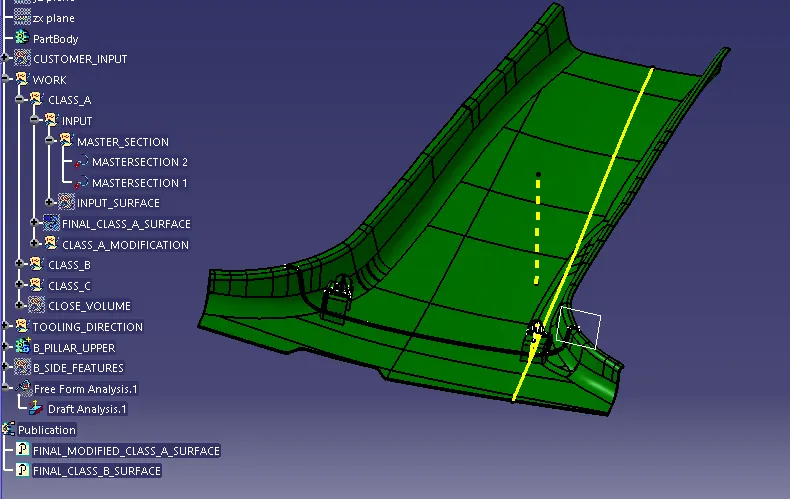
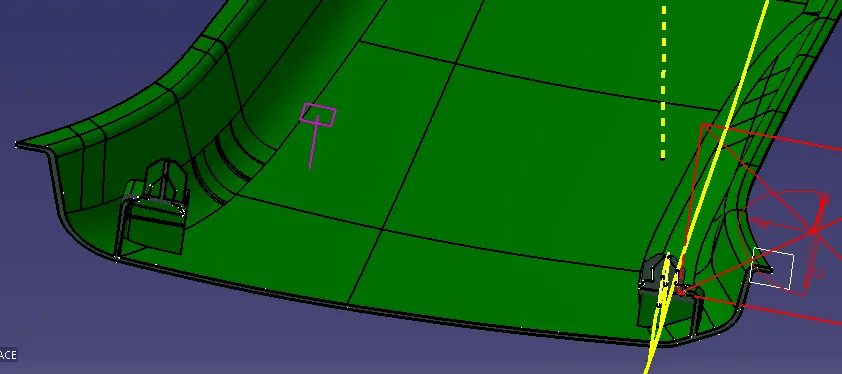
Above picture shows the closed body of B-pillar lower and cross section view of the part.
Step 4- Create B-surface features by following master section.
Dog-house with 4 way locator is created by following the master section.
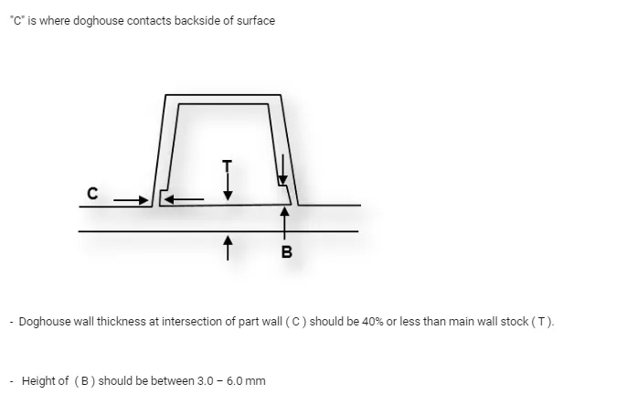
Above design rule is followed while designing the dog-house.
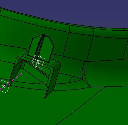 Dog house with 4way locator
After creating one dog house with 4 way locator symmetric command is used to create another one in the opposite side.
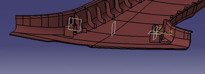
As we can see in the above picture that the middle plane is used for creating another dog-house with 4 way locator by using symmetric command.
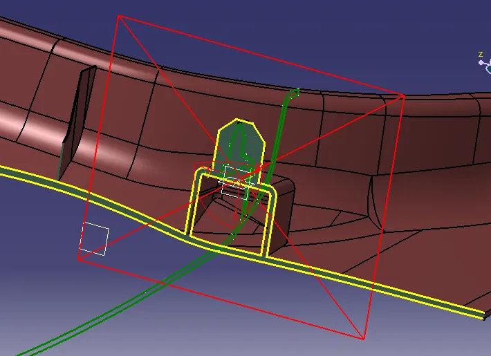 Section view of B-pillar lower with B-side feature that is dog house and locator.
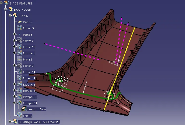
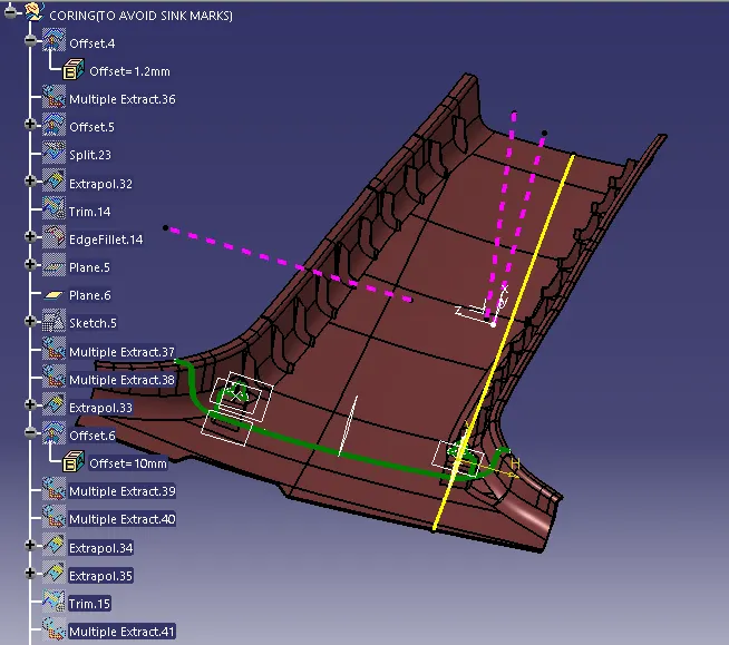
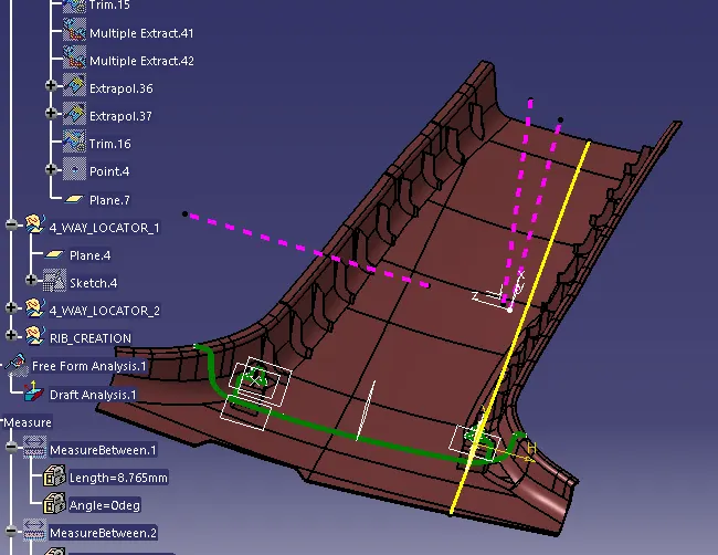
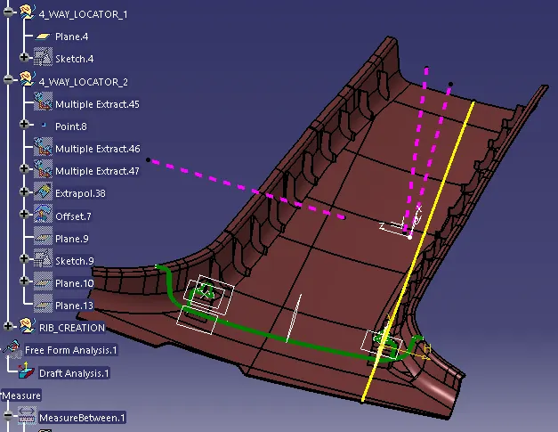
Tree structure for designing dog house and creating coring on the dog house to avoid sink mark is shown below:-
STEP-5- Ribs creation.
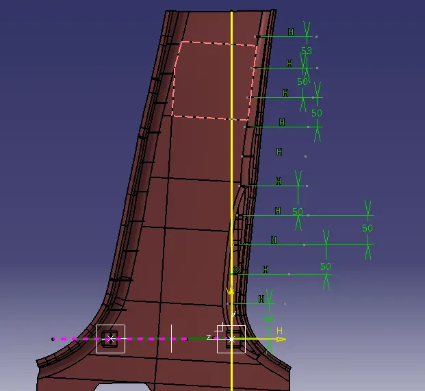
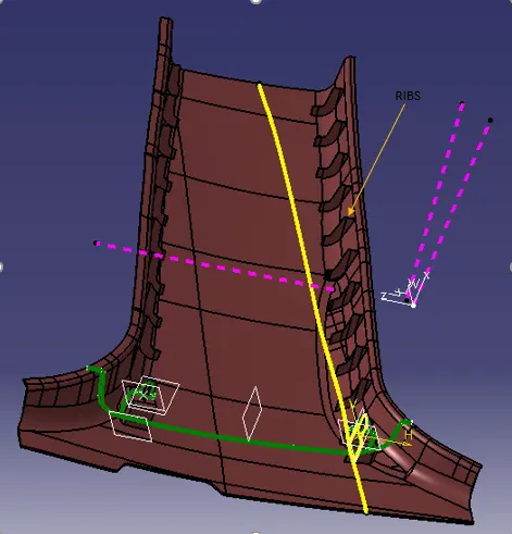
Design rule for rib is that the distance between two ribs should be 50mm(min) and from B surface features it is kept as 60mm
Step 6- B-pillar Draft analysis.
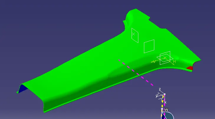
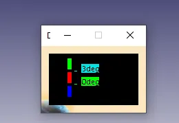
Above picture shows the draft analysis of class-A surface , Nominal draft angle is 3deg, green colour shows that the class-A surface can be clear in the tooling direction created.
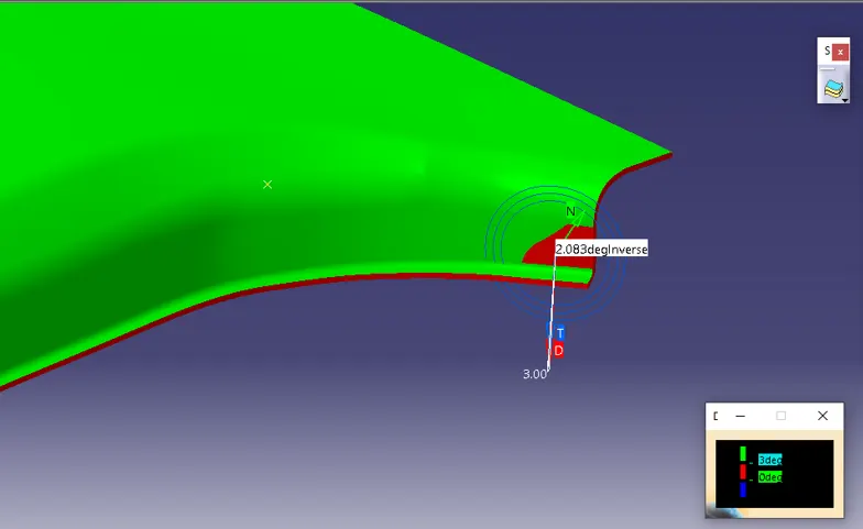
Minimum value in this area is 2.083 deg.
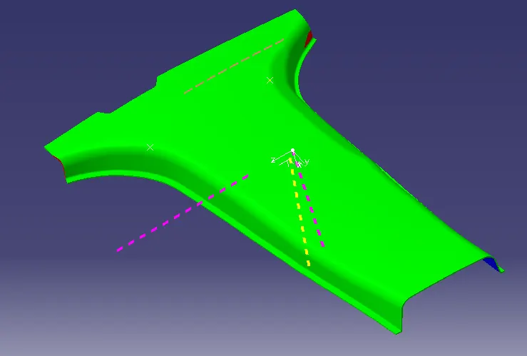
All areas with minimum draft of 3deg expect the area shown in red colour.
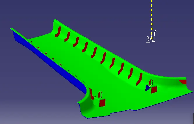
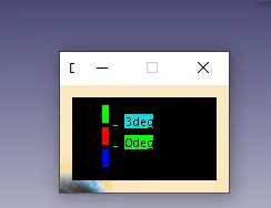
Above picture shows the draft analysis of B-Class surface,Nominal draft angle is 3 deg.
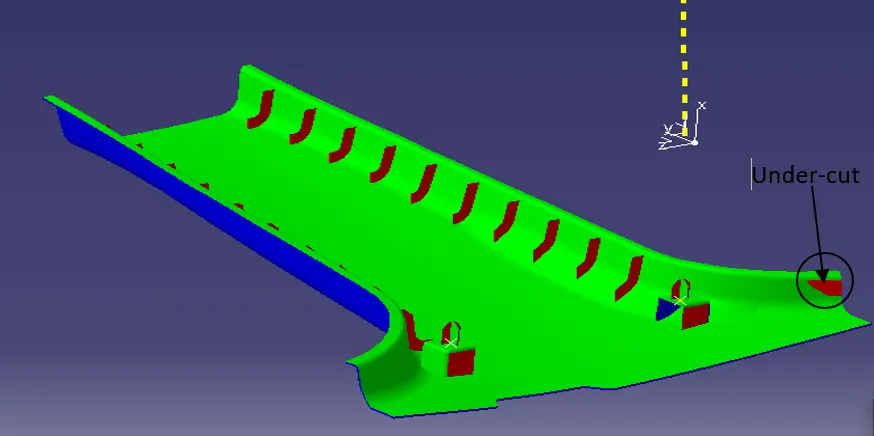
Red colour shows that it is an under-cut and it can not be clear along the tooling direction.
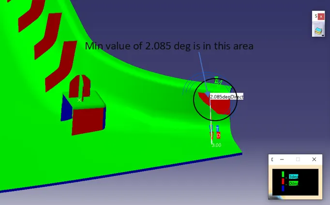
Draft analysis of C-surface
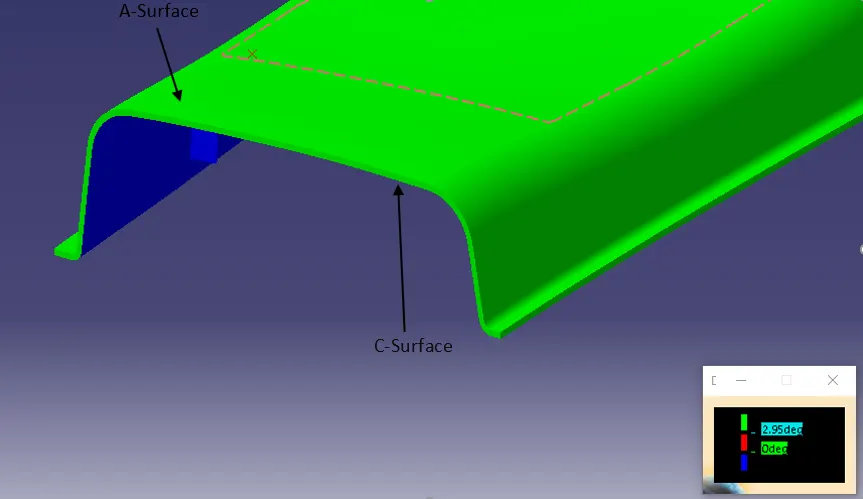
All faces of the C-surface are with 3 deg draft.
Draft analysis of Dog-house with 4-way locator.
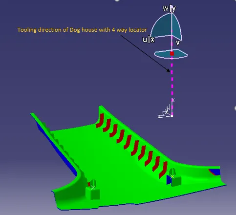
Dog-house with 4 way locator in Tooling direction of dog house.
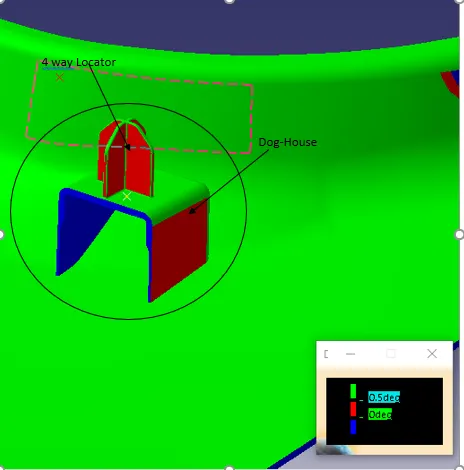
Above picture shows that the minimum of 0.5 deg draft is there on Red faces and 3 degree draft on other faces.
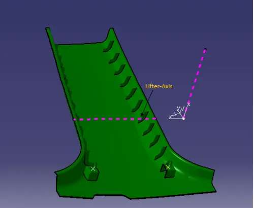 Lifter-direction of Dog-House.
Dog-House with 4 way locator in Lifter direction.
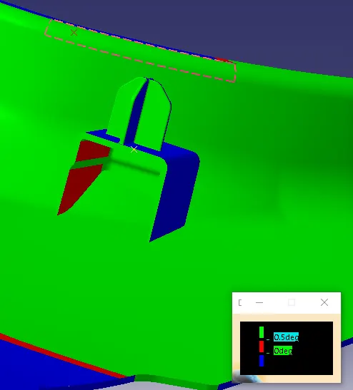
Above picture shows that the minimum of 0.5 deg draft is there on Red faces and 3 degree draft on other faces.
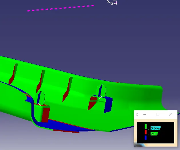 Draft analysis of 1st Dog house with 4 way locator in the lifter direction.
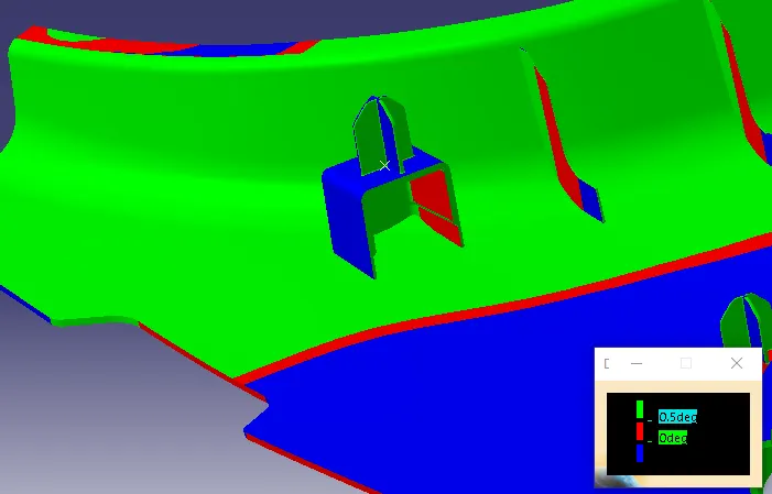 Draft analysis of 2nd Dog house with 4 way locator in the lifter direction.
Draft analysis of Rib in the main tooling direction
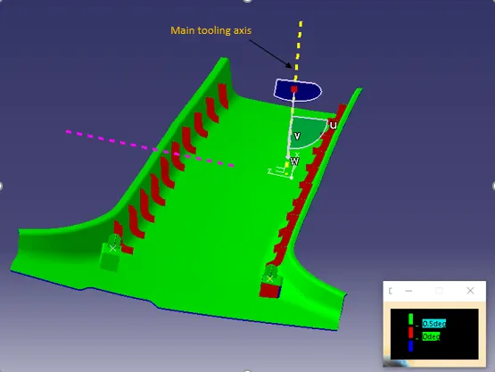
Above picture shows that the minimum of 0.5 deg draft is there on Red faces.