Week 9 - Parametric study on Gate valve.
Aim- To perform a parametric study on the gate valve simulation by setting the opening from 10% to 80%.
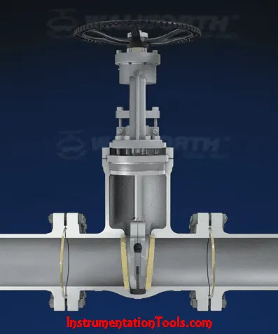
Introduction- A gate valve, also known as a sluice valve, is a valve that opens by lifting a barrier (gate) out of the path of the fluid. Gate valves require very little space along the pipe axis and hardly restrict the flow of fluid when the gate is fully opened. The gate faces can be parallel but are most commonly wedge-shaped (in order to be able to apply pressure on the sealing surface).
Gate valves are used to shut off the flow of liquids rather than for flow regulation. When fully open, the typical gate valve has no obstruction in the flow path, resulting in very low flow resistance. The size of the open flow path generally varies in a nonlinear manner as the gate is moved.
Bonnet-
Bonnets provide leakproof closure for the valve body. Gate valves may have a screw-in, union, or bolted bonnet. A screw-in bonnet is the simplest, offering a durable, pressure-tight seal. A union bonnet is suitable for applications requiring frequent inspection and cleaning. It also gives the body added strength. A bolted bonnet is used for larger valves and higher pressure applications.
Theory- A parameter is defined as a numerical or other measurable factor forming one of a set that defines a system or sets of conditions of its operation. Parameters are elements of a system that are useful or critical to identifying a system or evaluating a system’s performance, status, or condition. As an example, parameters of an equation modeling movement could include the mechanics, masses, dimensions and shapes, and densities and viscosities of fluids within the system. A parametric study on a gate valve is carried out in this report. A parametric analysis, also known as a sensitivity analysis, is the study of the influence of different geometric or physical parameters or both on the solution of the problem.
Parametric analysis is based on user-defined solving scenarios, producing “unrefined” solutions. These results need to post-processed in order to find the optimal solution or compromise in an overall design.
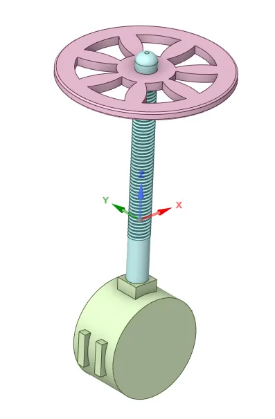
In our scenario the parameter that is changed will be the amount by which the barrier or the gate opens. This is done by moving the gate disc along the spindle and creating a parametric study in SpaceClaim, details have been explained further in the report.
Solving and modelling approach-
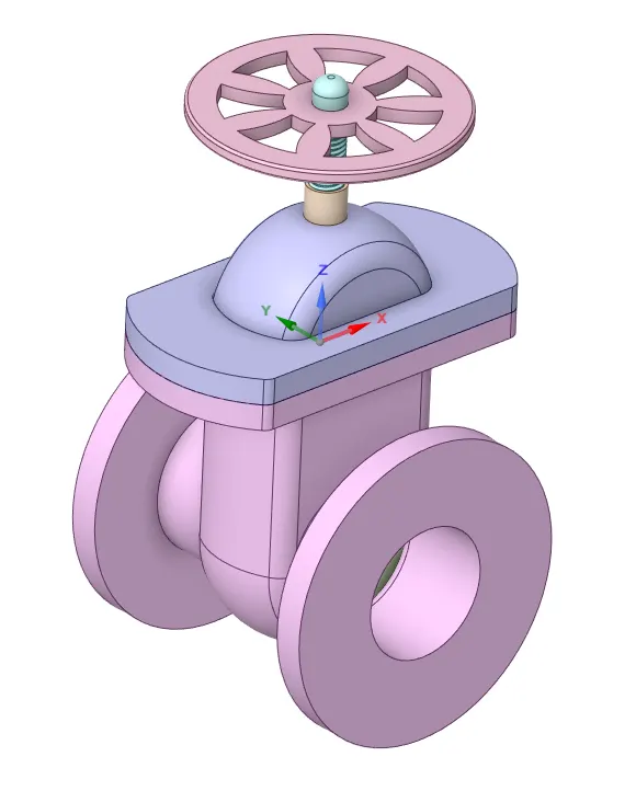
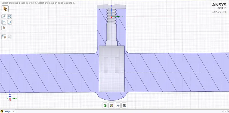
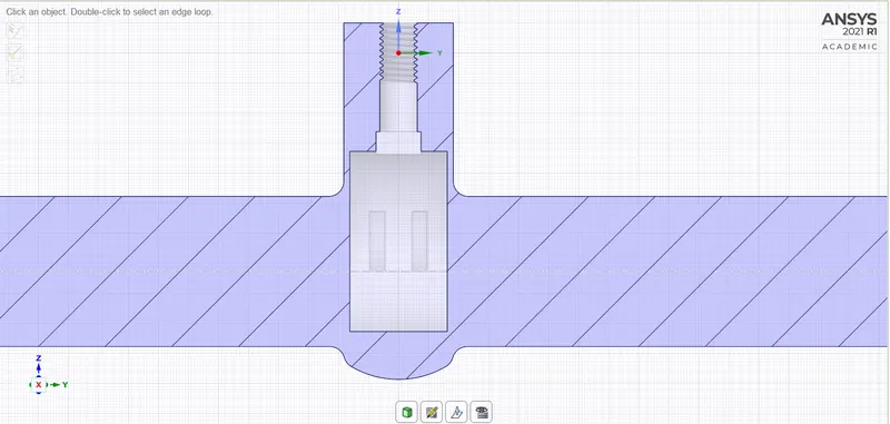
The geometry of the gate valve is loaded in SpaceClaim and the volume is extracted. The gate disc is shifted through its position along the spindle by varying the distance from 10mm to 80mm. The parametric study is carried out using the parametric study option created while moving the gate disc in the 'Groups' tab on the left side of the window.
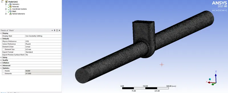
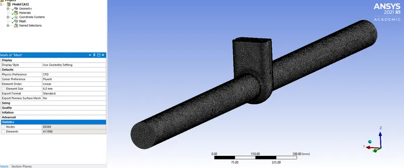
The Meshing is done in Ansys Mesh keeping the element count under 512K. Giving named selections properly which account for just two of them viz. inlet and outlet.
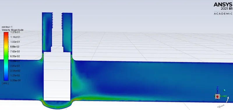
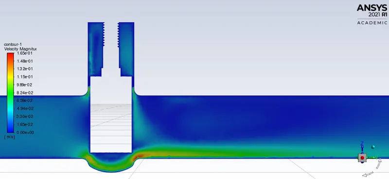
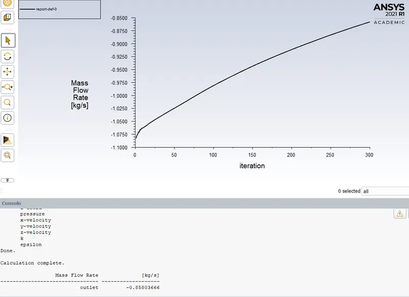
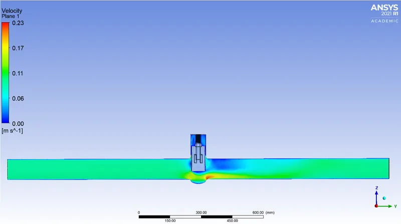
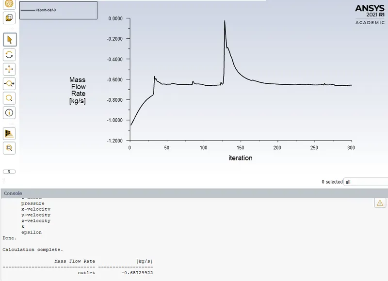
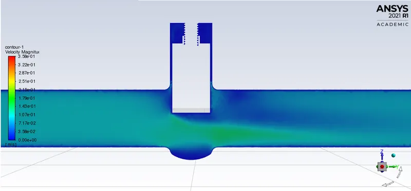
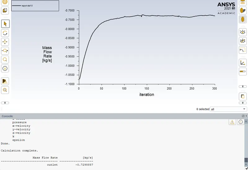
Fluent is operated to solve the simulation. An r-plot is created of mass flow rate at outlet. A velocity contour gives a visual of the velocity of the air flowing through the valve.
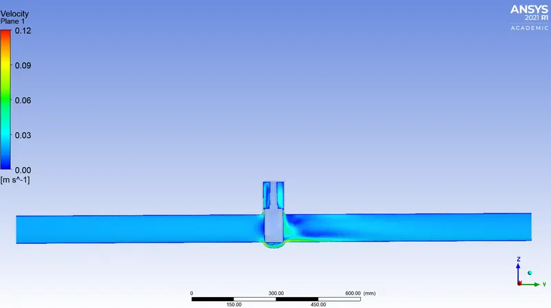
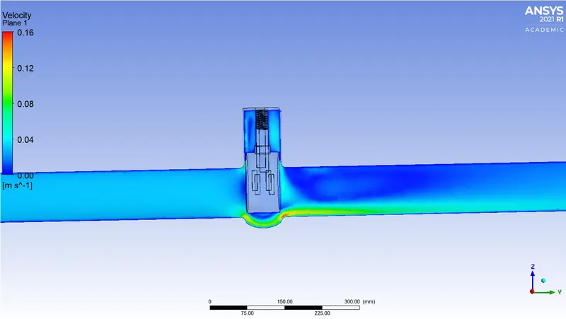
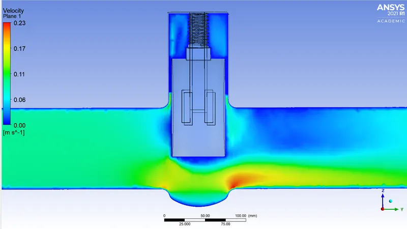
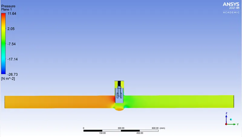
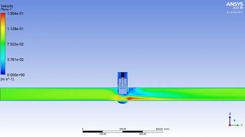
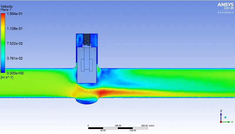
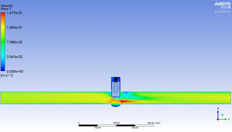
To have intricate details of the velocity and pressure contours CFD-Post serves the best.
Pre-processing and solver setting-
Geometry-

Fluid extraction-
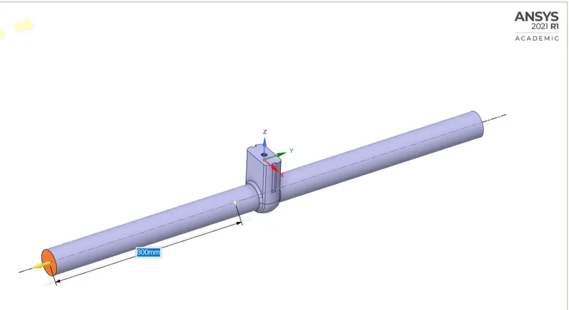
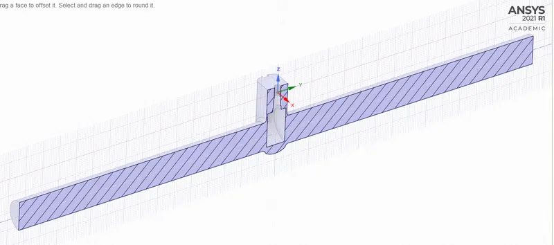
The inlet and outlet has been attached with extra volume to have a better visualization over the velocity and pressure contours.
Parametric study function-
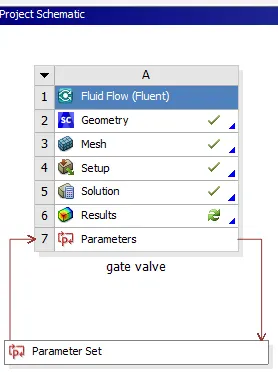
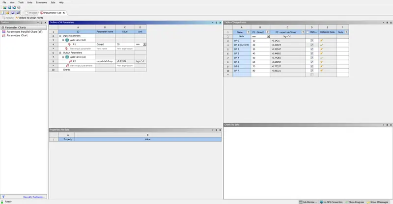
To obtain results from every design point defined in the paramteric window, right click on the row and click set as current.
Geometry, Mesh, Fluent results and CFD-Post contours are attached below for every design point.
Results-
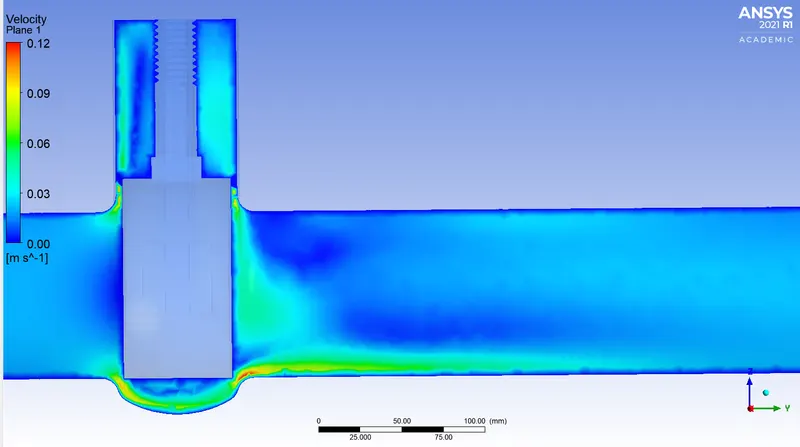
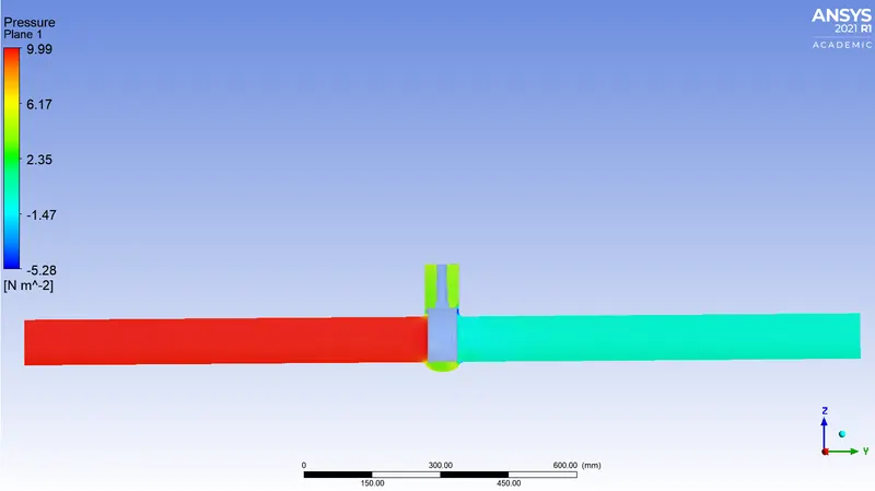
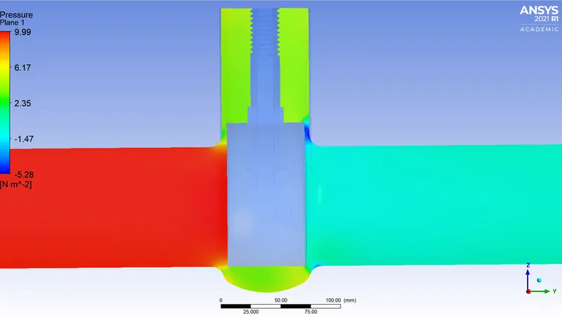
10mm
Geometry-
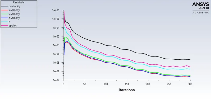
Residuals-
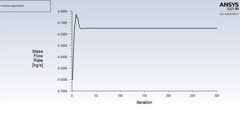
Mass flow rate-
Velocity contour(Fluent)-
CFD-Post-
Velocity contour-
Pressure contour-
20mm
Geometry
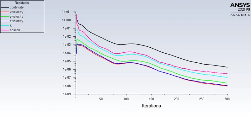
Residuals-
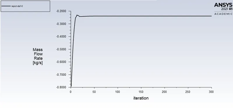
Mass flow rate-
Velocity contour(Fluent)-
CFD-Post-
Velocity contour-
Pressure contour-
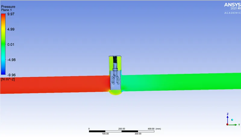
30mm
Meshing-
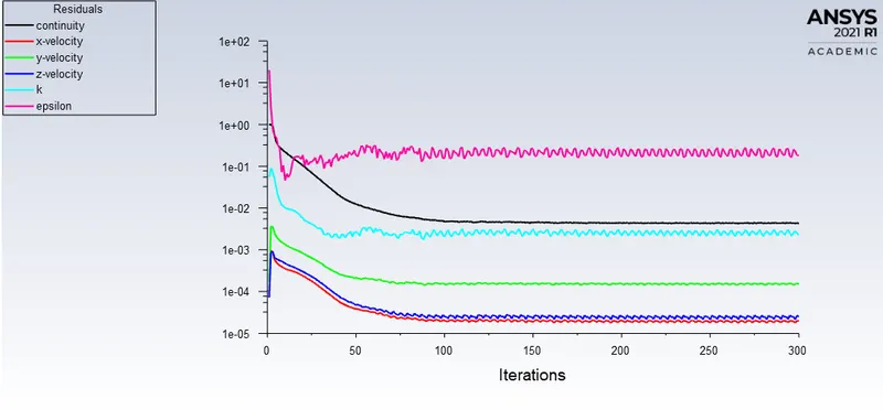
Residuals-
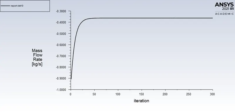
Mass flow rate-
Velocity contour(Fluent)-
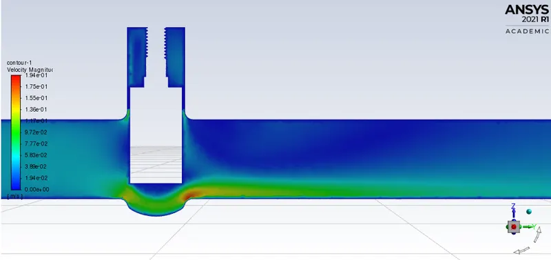
CFD-Post-
Velocity contour-
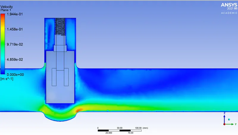
Pressure contour-
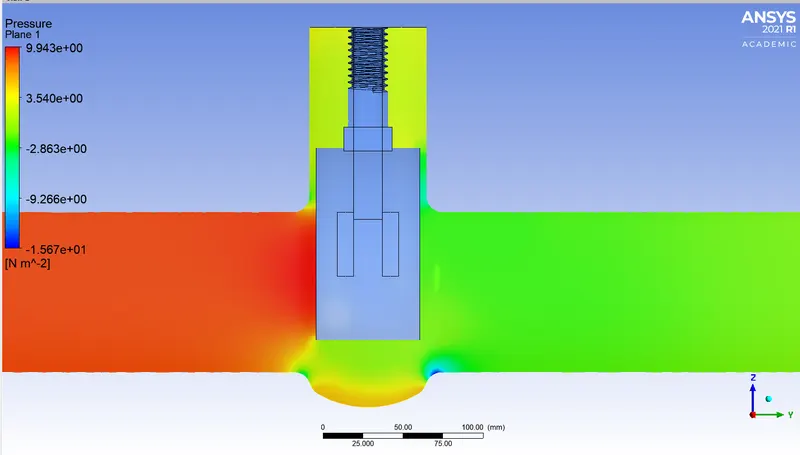
40mm
Geometry-
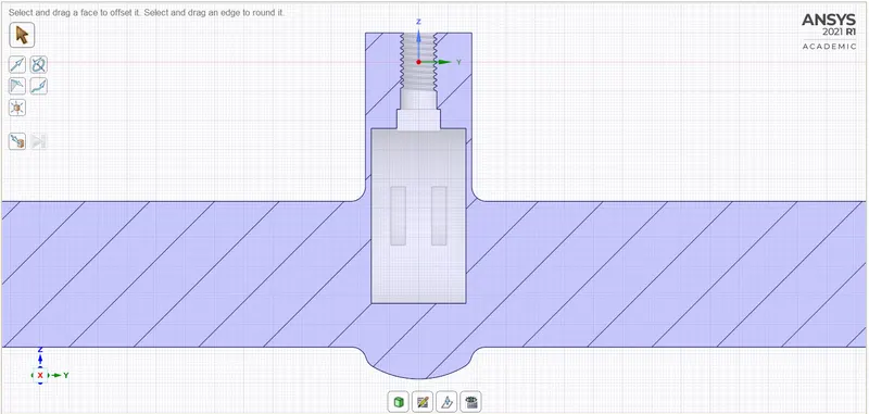
Meshing-
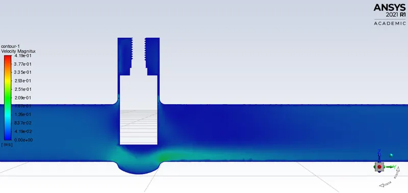
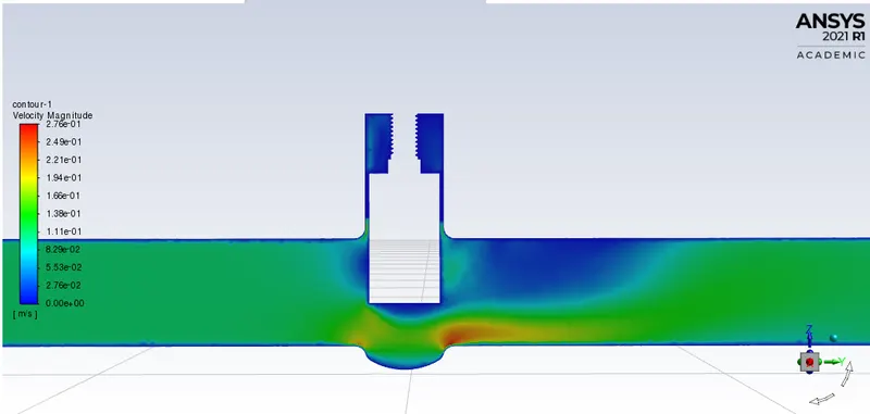
Velocity contour(Fluent)-
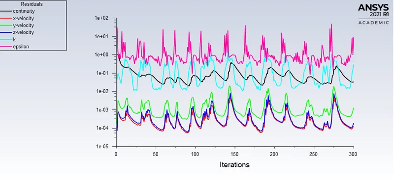
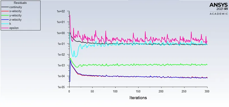
Residuals-
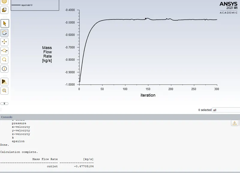
Mass flow rate-
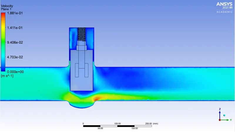
CFD-Post-
Velocity contour-
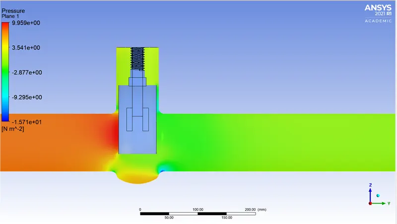
Pressure contour-
50mm
Velocity contour-
Residuals-
Mass flow rate-
CFD-Post-
Velocity contour-
Pressure contour-
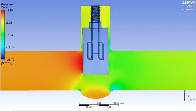
60mm
Geometry-
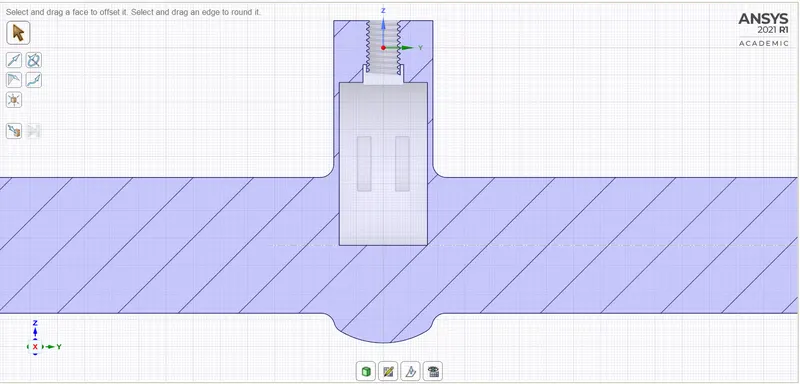
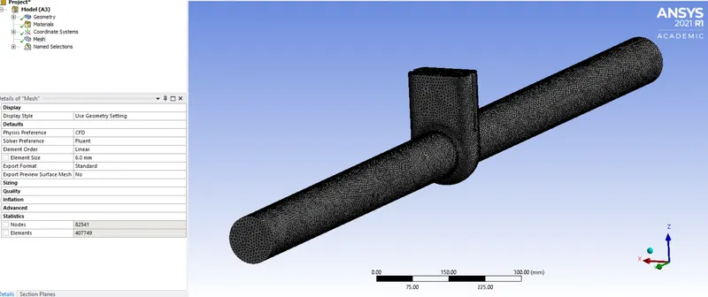
Meshing-
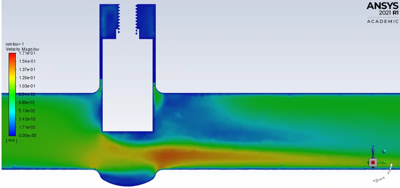
Velocity contour(Fluent)-
Mass flow rate-
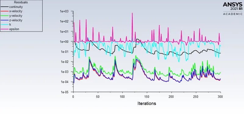
Residuals-
CFD-Post-
Velocity contours-
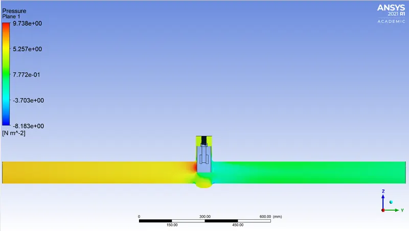
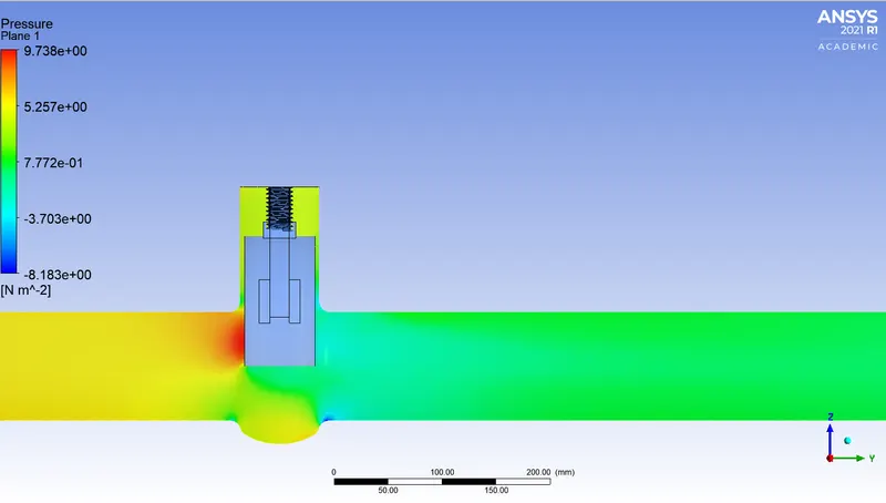
Pressure contours-
70mm
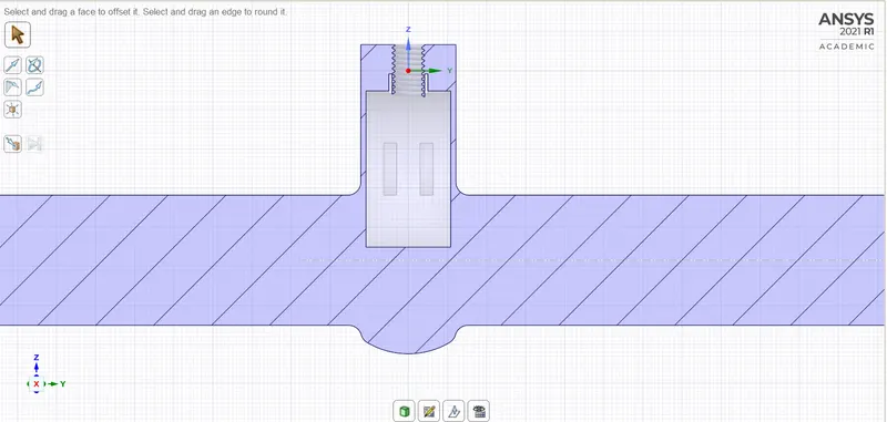
Geometry-
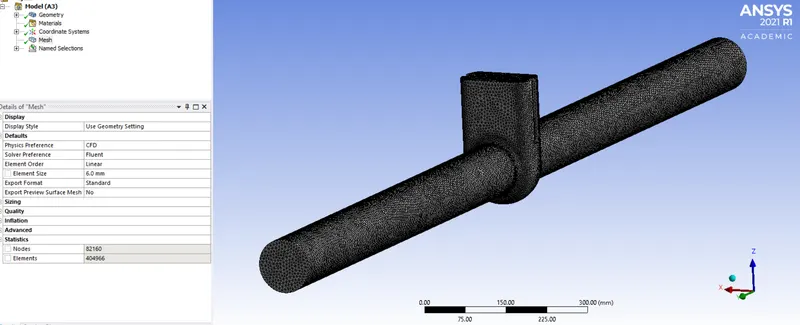
Meshing-
Velocity contour(Fluent)-
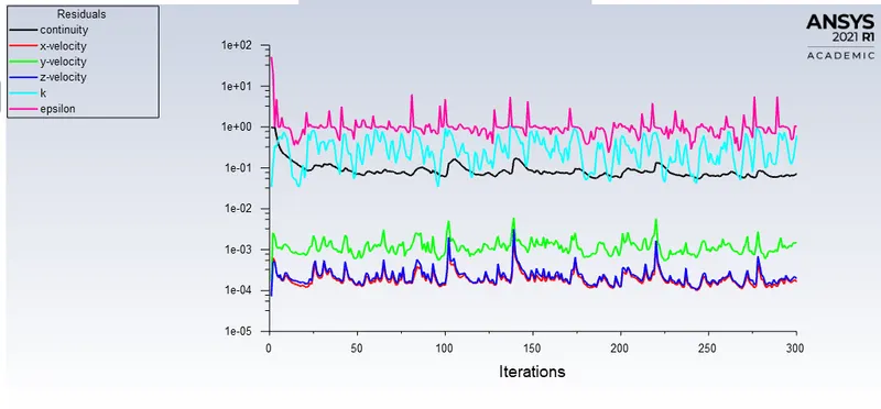
Residuals-
Mass flow rate-
CFD-Post-
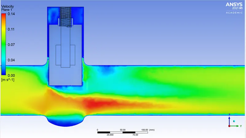
Velocity contour-
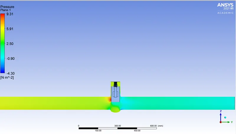
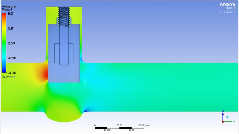
Pressure contour-
Flow rate-
The volumetric flow rate is the volume of fluid which passes per unit time; usually it is represented by the symbol Q. The SI unit is cubic metres per second. Another unit used is standard cubic centimetres per minute.

where,
 = volumetric flow rate
 = flow velocity
 = cross-sectional vector area
Flow coefficient-
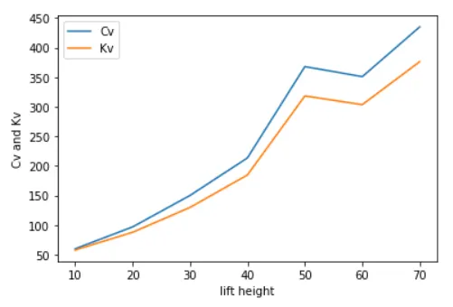
Valve Flow Coefficient (Cv) is a valve’s capacity for a liquid or gas to flow through it. It is technically defined as “the volume of water at 60°F (in US gallons) that will flow through a valve per minute with a pressure drop of 1 psi across the valve.” the larger the opening in a valve, the larger the Cv. As a valve is opening, the Cv increases until the valve is fully open, where it reaches its highest possible Cv, or 100% open Cv.
Flow coeffcient when calculated in metric units is denoted by Kv.

where,
 = flow coefficient
= flow rate
 = Specific gravity of the fluid
 = pressure drop across the valve
And,
Cv=Kv*1.156
The table for calculations is given below
| Sr.No. | Lift height | Mass flow rate at outlet(kg/s) | Mass flwo rate at outlet(gpm) | Pressure at inlet(Pa) | Pressure at outlet(Pa) | Pressure difference(Pa) | Pressure difference(psi) | Cv | Kv |
| 1 | 10mm | 0.1421 | 2.2591 | 10 | 0.18 | 9.82 | 0.001424 | 59.866 | 51.7871 |
| 2 | 20mm | 0.21924 | 3.4854 | 10 | 1.07 | 8.93 | 0.001295 | 96.854 | 83.7837 |
| 3 | 30mm | 0.32547 | 5.1743 | 10 | 1.8 | 8.2 | 0.001189 | 150.058 | 129.808 |
| 4 | 40mm | 0.44892 | 7.1358 | 10 | 2.3 | 7.7 | 0.000111679 | 213.529 | 184.7136 |
| 5 | 50mm | 0.74265 | 11.8066 | 10 | 2.9 | 7.1 | 0.00102977 | 367.92 | 318.27 |
| 6 | 60mm | 0.68292 | 10.8559 | 10 | 3.4 | 6.6 | 0.000957 | 350.92 | 303.564 |
| 7 | 70mm | 0.77257 | 12.2808 | 10 | 4.5 | 5.5 | 0.000797 | 435.0082 | 376.3047 |
Conclusion-
- As the lift height is increased the pressure difference decreases.
- With the increases in lift height the flow coefficient also increases.
- Parameters in Workbench helps to solve the simulation with lesser time and efforts.
- Negative value of mass flow rate in fluent indicates that the fluid is exiting the valve.