Week 9 - Parametric study on Gate valve.
Aim:- To perform a parametric study on the gate valve simulation by setting the opening from 10 % to 80%.
Objective:-
- To obtain the mass flow rates at the outlet for each design point.
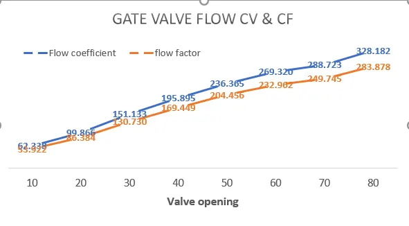
- To Calculate the flow coefficient and flow factor for each opening and plot the graph.
- Discuss the results of the mass flow rate and flow coefficient.
Introduction -
A gate valve, also known as a sluice valve, is a valve that opens by lifting a barrier (gate) out of the path of the fluid. Gate valves require very little space along the pipe axis and hardly restrict the flow of fluid when the gate is fully opened.
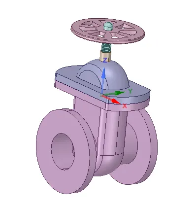
A gate valve's main components are body, seat, gate, stem, bonnet, and actuator (Figure). The primary operation mechanism is straightforward. Turning the handwheel rotates the stem, which moves the gate up or down via the threads. They require more than one 360° turn to fully open/close the valve. Lifting the gate from the path of the flow, the valve opens. Lowering the gate to its closed position seals the bore resulting in a full closure of the valve.
Gate valves are used to shut off the flow of liquids rather than for flow regulation.The size of the open flow path generally varies in a nonlinear manner as the gate is moved. This means that the flow rate does not change evenly with stem travel. Depending on the construction, a partially open gate can vibrate from the fluid flow.
Modeling & Ansys simulation solving approach :
Geometry -
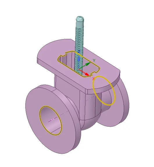
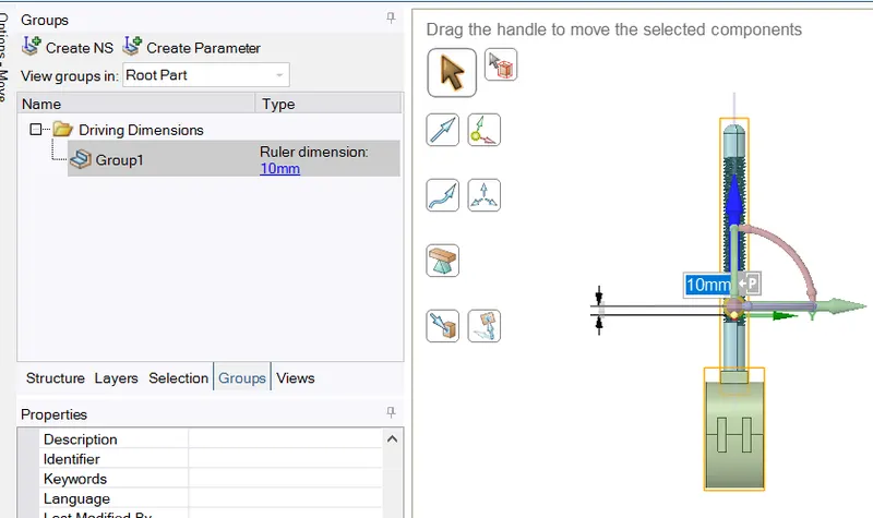
- To parametrize the lift of gate disc, Spindle & gate disc components are selected to moved along Z-axis.
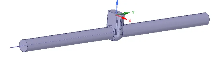
- Fluid volume is extracted from Inlet, Outlet & bonnet egdes.
- Fluid flow regions at Inlet & outlets are extended by pull tool to a length of 0.8m.
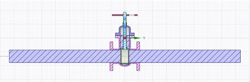
- Solid goemetry is hidden & suppresed for physics.
Parametric approach -
- To Activate parameters during Lift move an 'P' icon is selected.
- Parameter is defined in a group & dimension can be modified as user Input in Output parameter window in workspace.
- To abapt fluid volume to changing geometry is done by changing the Fluid volume settings to 'update body as context' (current bodies). This should be done keeping spindle & disc visible throughout.
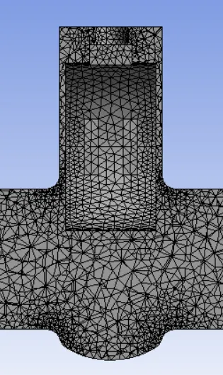
Mesh -
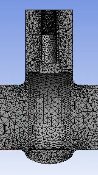
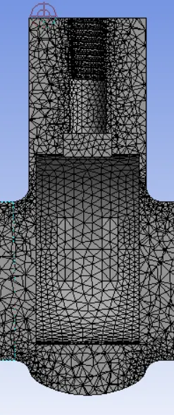
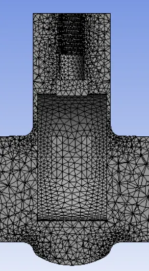
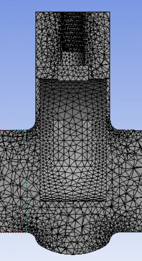
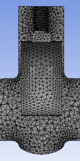
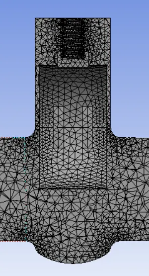
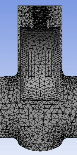
- Global mesh body size of 8mm was done. Which produced No. of elements = 241822
- Inlet & outlet named selection given.
Below are the sectional view at (10% varying) valve lifting different cases.
10mm 20mm 30mm
40mm 50mm 60mm
70mm 80mm
Setup-
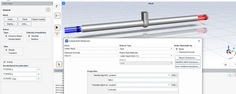
- Gravity is enabled in Z-axis. Steady state anslysis is performed.
- For analysis, here Water is used as only fluid material in cell zone. (default air material deleted).
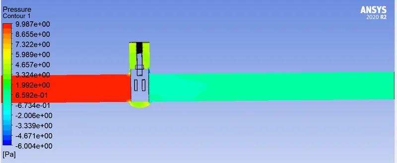
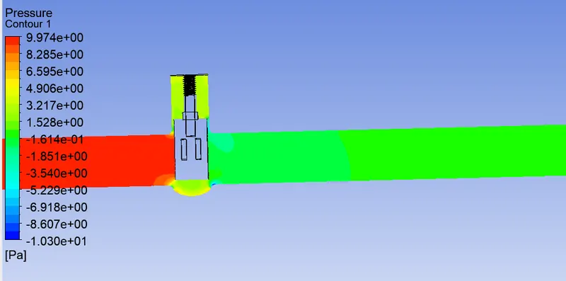
- BC for Inlet is changed to 'Pressure-Inlet' type & typical value choosed is 10pa & outlet to 0pa.
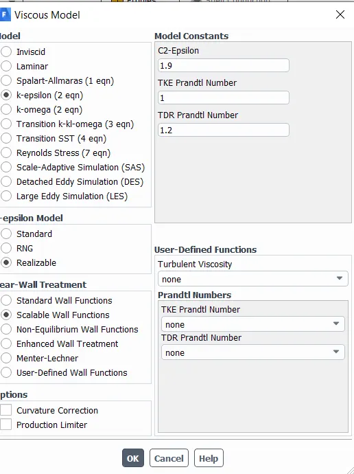
- For the given pressure Inlet value, fluid is turbulent, hence K-epsilon scalable wall function is used.
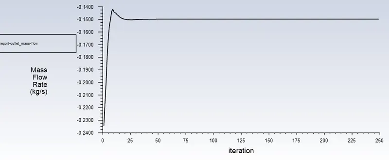
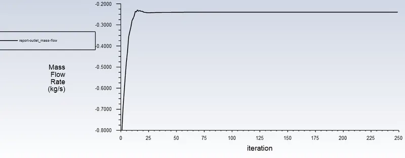
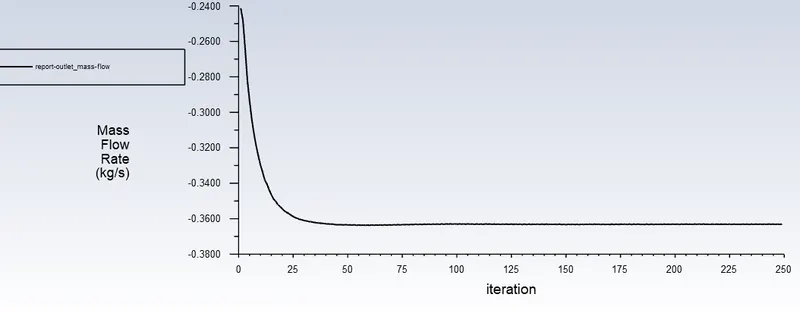
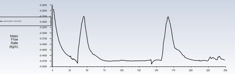
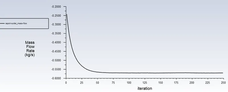
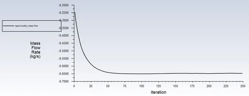
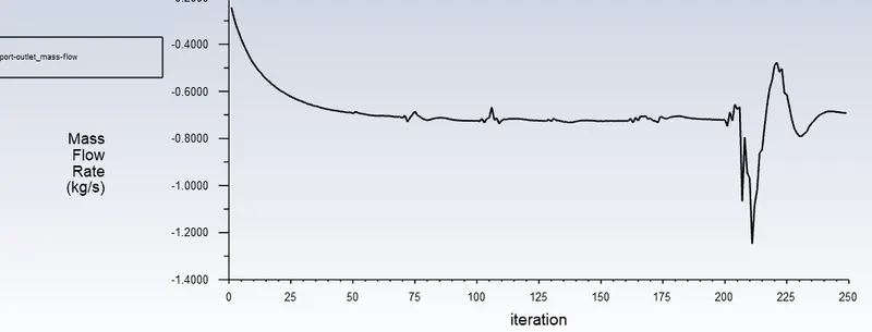
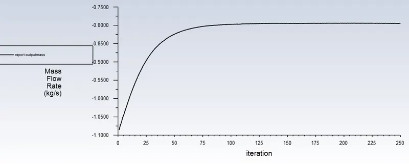
- Mass flow at Outlet Report created & 'create output parameter' is enabled.
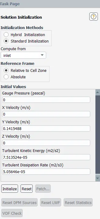
- Std. Intialization along Inlet is computed.
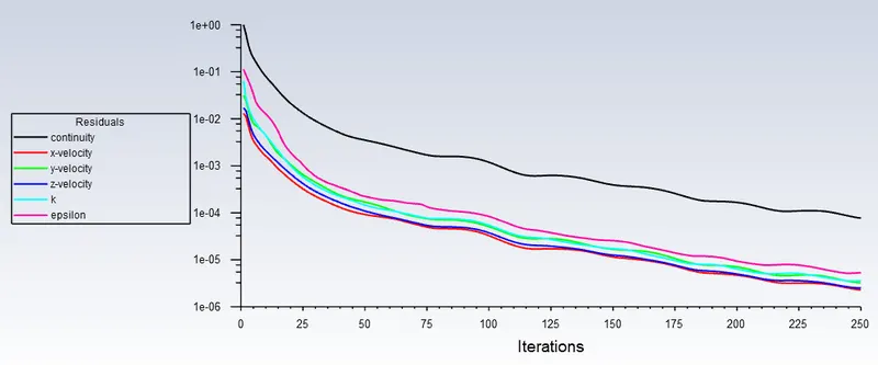
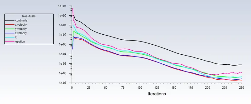
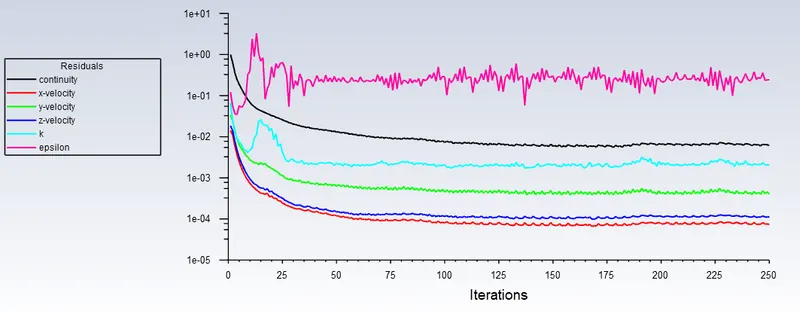
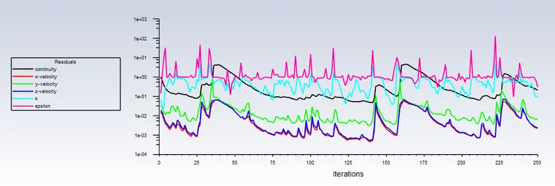
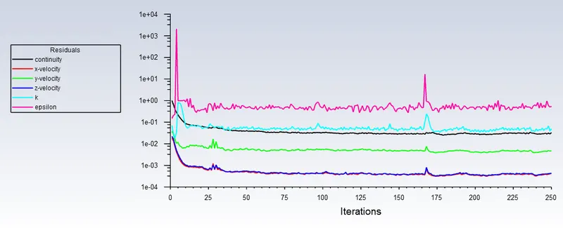
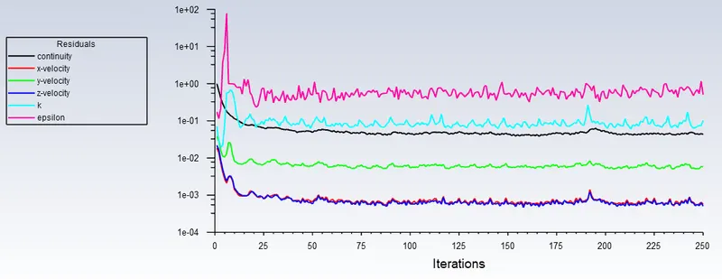
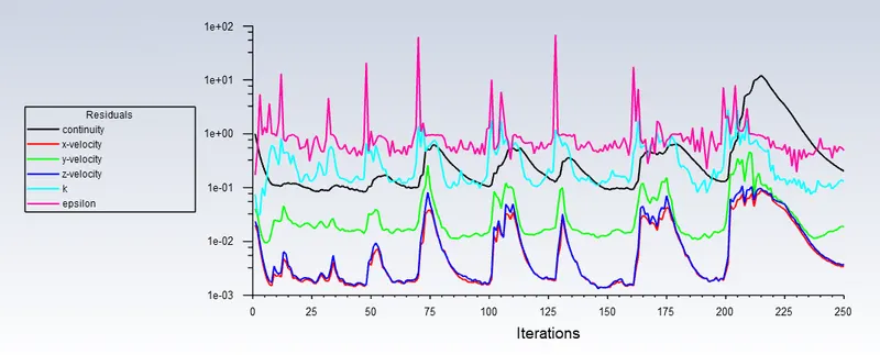
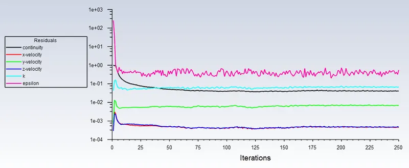
- 250 Iterations are run through all cases & found a decent Residual convergence.
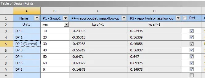
- Now for Running in parametric approach, parametrs window in workspace is opened. Where in the tabel of design points new value of lift parametres are provided & data is retained to view the solution by setting to current.
Results -
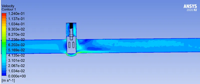
Lift = 10mm
Lift = 20mm
Lift = 30mm
Lift = 40mm
Lift = 50mm
Lift = 60mm
Lift = 70mm
Lift = 80mm
Parametric design points result-
Note - Here deign point DP6 is 10mm case.
| Gate valve position |
Mass flow rate kg/s |
Mass flow rate gpm |
Pressure drop PSI |
Specific gravity water |
Flow coefficent (Gpm per Psi) Cv | Flow factor Cf |
| 10 | 0.14978 | 2.374 | 0.00145038 | 1 | 62.338 | 53.922 |
| 20 | 0.23995 | 3.803 | 0.00145038 | 1 | 99.866 | 86.384 |
| 30 | 0.36313 | 5.756 | 0.00145038 | 1 | 151.133 | 130.730 |
| 40 | 0.47068 | 7.460 | 0.00145038 | 1 | 195.895 | 169.449 |
| 50 | 0.567919 | 9.002 | 0.00145038 | 1 | 236.365 | 204.456 |
| 60 | 0.6471 | 10.257 | 0.00145038 | 1 | 269.320 | 232.962 |
| 70 | 0.69372 | 10.996 | 0.00145038 | 1 | 288.723 | 249.745 |
| 80 | 0.78853 | 12.498 | 0.00145038 | 1 | 328.182 | 283.878 |
Comments -
- At 70 & 40% residuals frequency or variation was high. Which could cause cavitation or water hamering in outlet pipe.
- When valve opening increases definitely mass flow at outlet should increase, same verified from results.
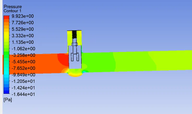
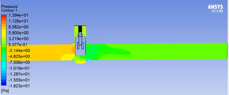
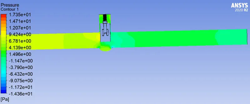
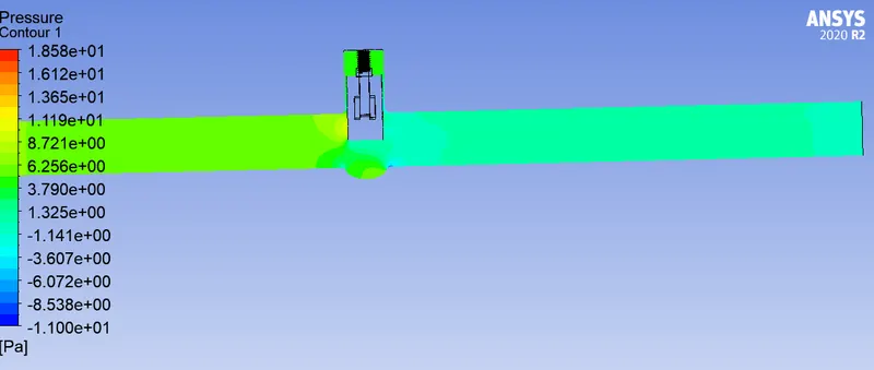
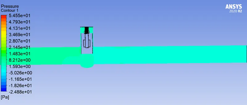
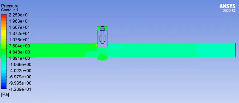
- From pressure contours it is clear that pressure difference is large at lower opening/lift.
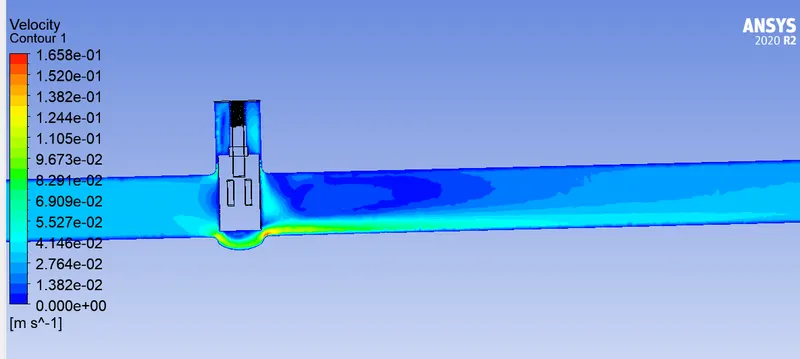
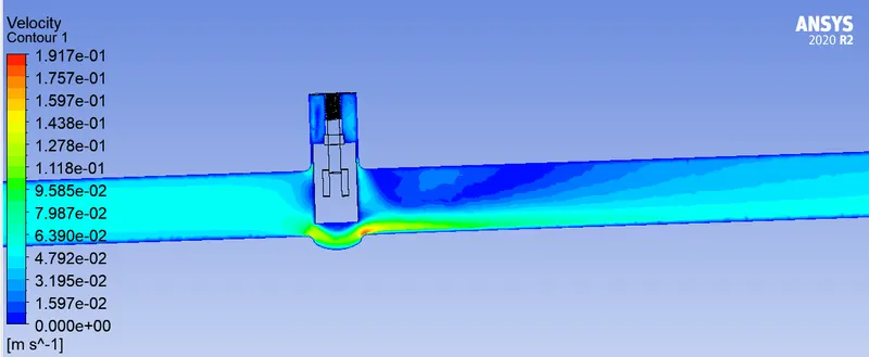
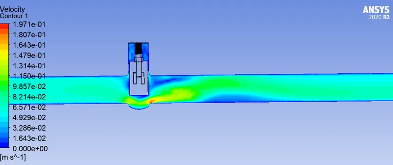
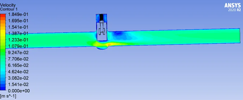
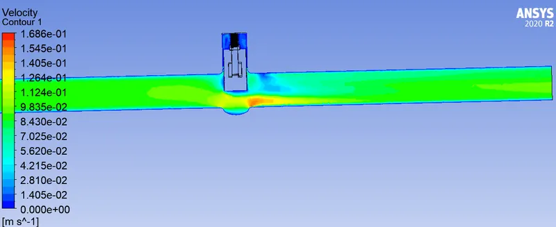
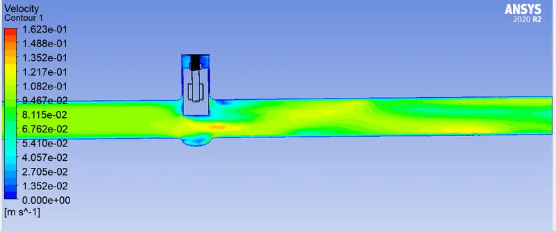
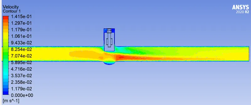
- Velocity contours smooth out at outlet when valve opening increased.
- Flow factor & coefficient are vaying linearly.