Week 9 - Parametric study on Gate valve.
AIM
Perform a parametric study on the gate valve simulation by setting the opening from 10 % to 80%.
- Obtain the mass flow rates at the outlet for each design point.
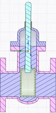
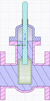
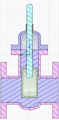
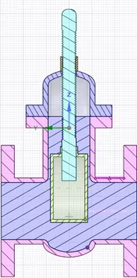
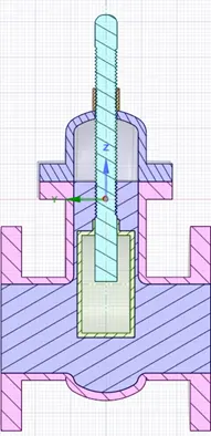
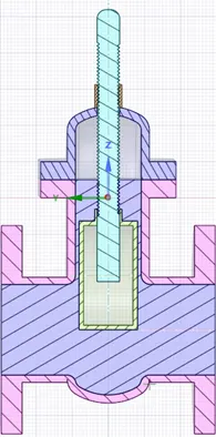
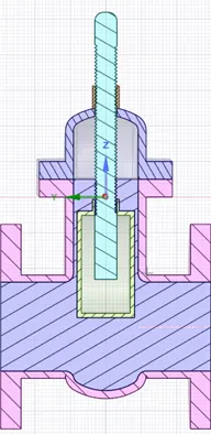
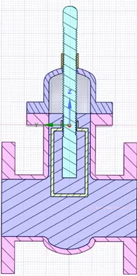
- Show the cut section view for the design points to show that the gate disc has lifted and fluid volume has adapted accordingly.
- Show the velocity contour animations for the design points.
INTRODUCTION
A gate valve, also known as a sluice valve, is a valve that opens by lifting a barrier (gate) out of the path of the fluid. Gate valves are used to shut off the flow of liquids rather than for flow regulation.
OPERATION
A gate valve is generally used to completely shut off fluid flow or, in the fully open position, provide full flow in a pipeline. Thus, it is used either in the fully closed or fully open positions. A gate valve consists of a valve body, seat and disc, a spindle, gland, and a wheel for operating the valve. The seat and the gate together perform the function of shutting off the flow of fluid. Gate valves are generally not suitable for regulating flow or pressure or operating in a partially open condition. For this service, a plug valve or a control valve should be used. It must be noted that because of the type of construction a gate valve requires many turns of the hand wheel to completely open or close the valve.
Flow Factor
A Flow Factor (Kv) is the flow coefficient in metric units that is defined as the flow rate in cubic meters per hour (m3/h) of water with a pressure drop across the valve.
The Kv is related the head drop (Δh) or pressure drop (ΔP) across the valve with the flow rate (Q).
Flow factor Kv= `Q* root.((SG)/(delta P))`
Where Q= flow rate
SG= Specific gravity of water=1
Delta P = pressure difference
Flow Coefficient:
Valve Flow Coefficient (Cv) is a valve’s capacity for a liquid or gas to flow through it. It is technically defined as “the volume of water at 60°F (in US gallons) that will flow through a valve per minute with a pressure drop of 1 psi across the valve.”
In simpler terms, the larger the opening in a valve, the larger the Cv. As a valve is opening, the Cv increases until the valve is fully open, where it reaches its highest possible Cv, or 100% open Cv.
Flow factor Kv =0.865* Cv
Flow coefficient Cv= Kv/0.865
GEOMETRY
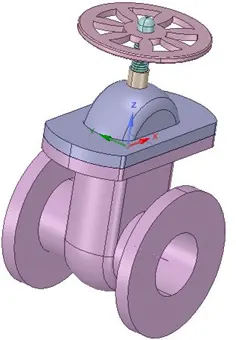
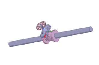
Volume Extract
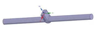
MESHING
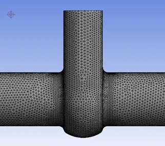
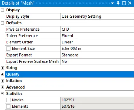
Element Size: 5.5 mm
Nodes: 102391
Elements: 507516
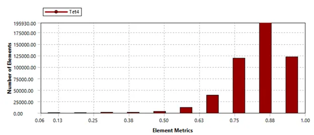
Element Quality
SOLVER SETUP
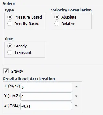
Type: Pressure Based
Time: Steady
Gravity: 9.81 in -ve Z direction
Viscous Model: K epsilon Realizable With Scalable Wall Functions
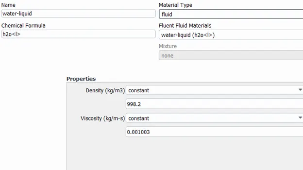
Materials used:
Water-Liquid
Boundary Conditions:
Inlet: Gauge Total Pressure – 10 Pa
Outlet: Gauge Pressure – 0 Pa
Initialization: Standard – Computed from inlet
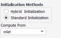
Time Scale Factor: 1
No of iterations: 250
Parametric Setup
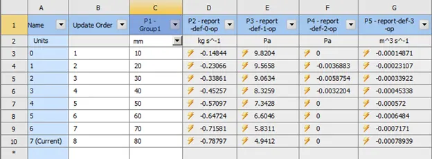
RESULTS
Position of gate valve
|
Case 1 : 10 mm |
Case 2: 20 mm |
Case 3: 30 mm |
Case 4: 40 mm |
 |
 |
 |
 |
|
Case 5: 50 mm |
Case 6: 60 mm |
Case 7: 70 mm |
Case 8: 80 mm |
 |
 |
 |
 |
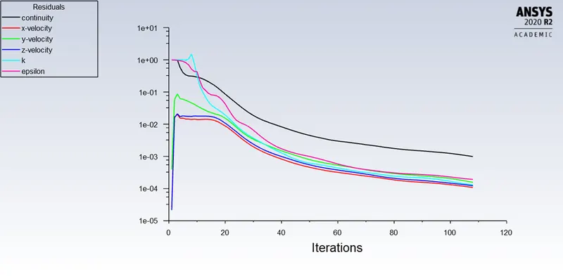
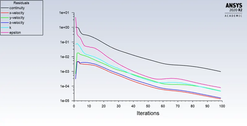
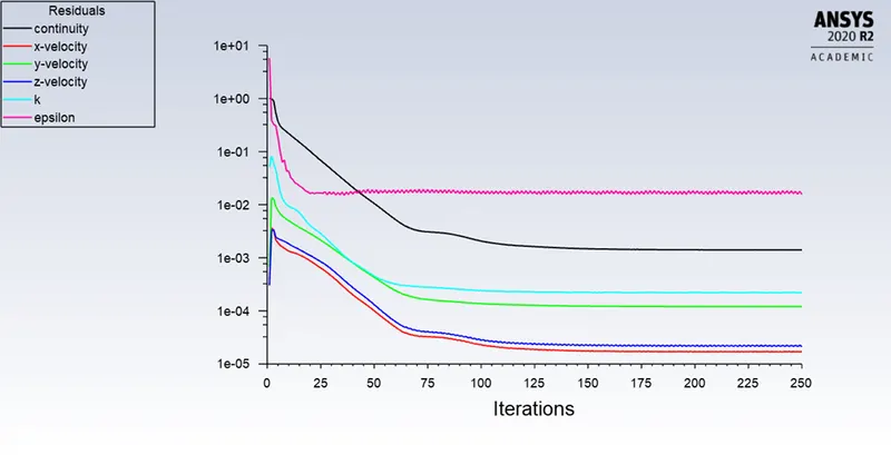
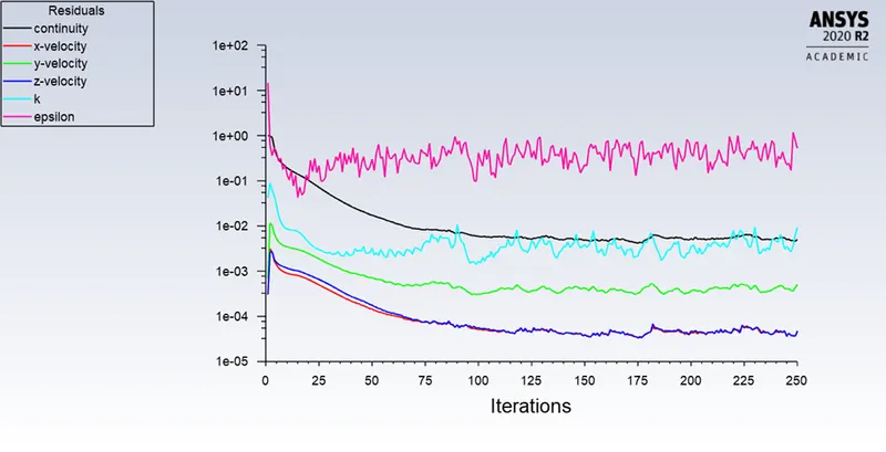
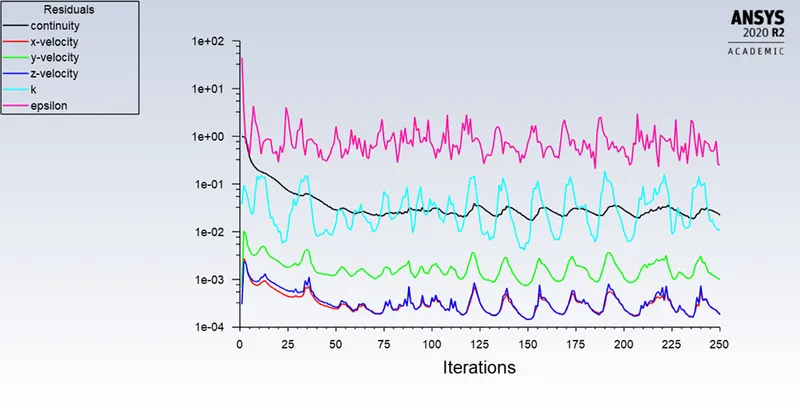
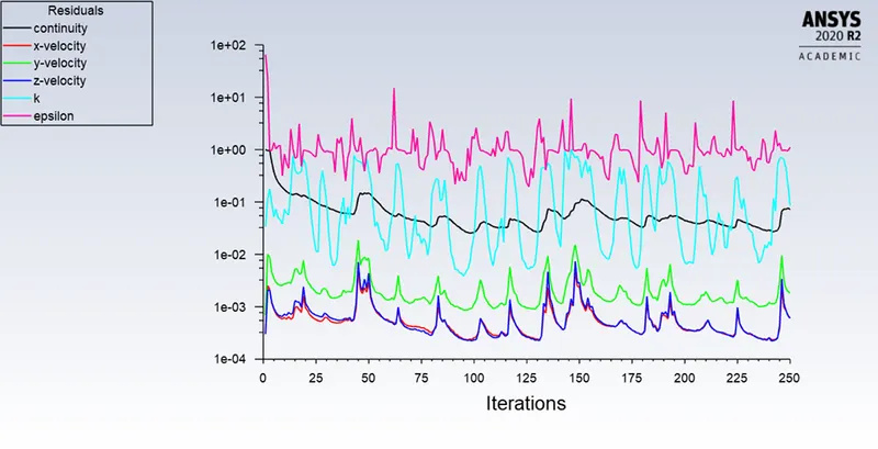
Residuals
|
Case 1 |
Case 2 |
 |
 |
|
Case 3 |
Case 4 |
 |
 |
|
Case 5 |
Case 6 |
 |
 |
| Case 7 | Case 8 |
|
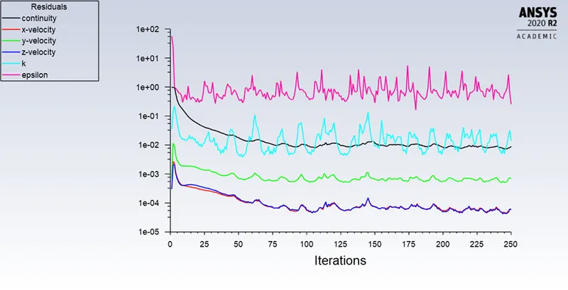 |
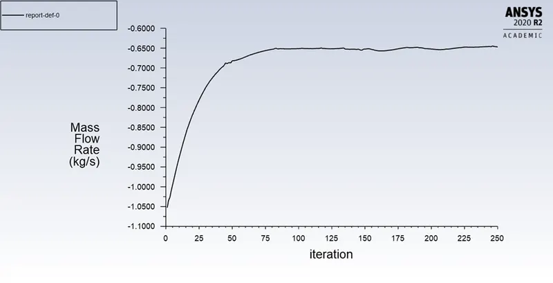
Mass Flow Rate
|
Case 1 |
Case 2 |
|
|
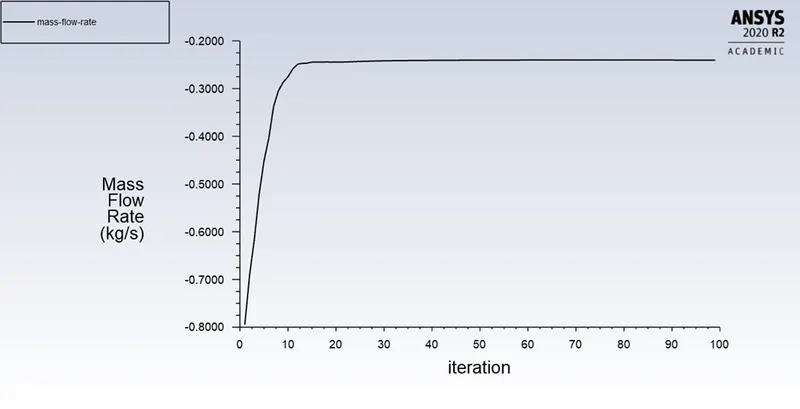 |
| Case 3 | Case 4 |
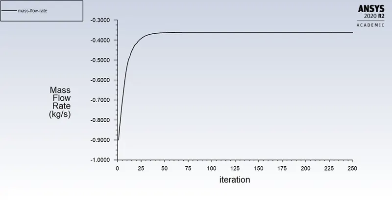 |
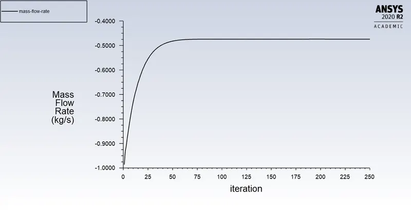 |
|
Case 5 |
Case 6 |
|
|
|
| Case 7 | Case 8 |
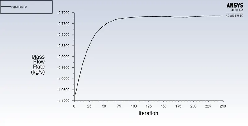 |
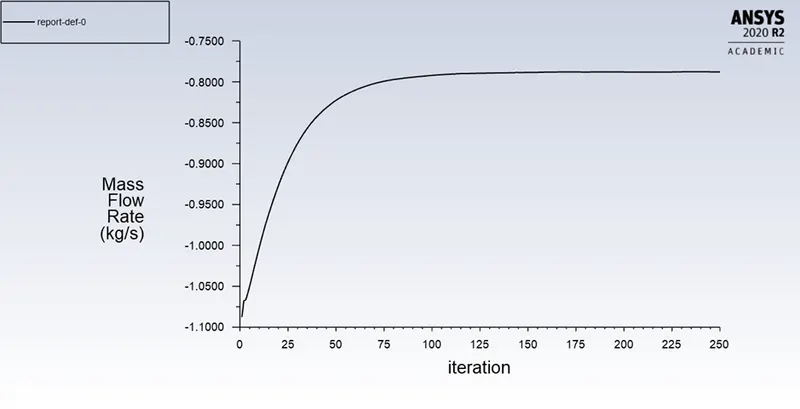 |
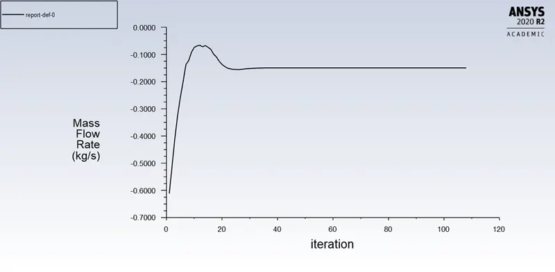
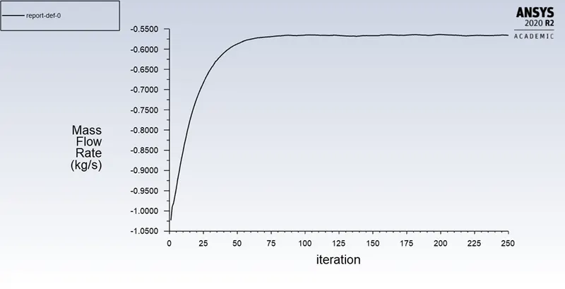
|
Position of gate valve |
Mass Flow Rate |
Inlet Pressure |
Outlet Pressure |
Pressure drop in bar |
Volume Flow Rate (m^3s-1) |
Volume Flow Rate |
Flow Factor |
Flow Coefficient |
|
(m^3h-1) |
||||||||
|
10 |
0.14844 |
9.8204 |
0.0000 |
0.00009820 |
0.00014871 |
0.5353 |
54.02 |
62.45 |
|
20 |
0.23066 |
9.5658 |
0.0037 |
0.00009562 |
0.000231072 |
0.8319 |
85.07 |
98.35 |
|
30 |
0.33861 |
9.0634 |
0.0059 |
0.00009058 |
0.000339217 |
1.2212 |
128.31 |
148.34 |
|
40 |
0.45257 |
8.3259 |
0.0032 |
0.00008323 |
0.000453383 |
1.6322 |
178.91 |
206.83 |
|
50 |
0.57097 |
7.3428 |
0.0000 |
0.00007343 |
0.000572003 |
2.0592 |
240.31 |
277.81 |
|
60 |
0.66434 |
6.4067 |
0.0000 |
0.00006407 |
0.000665541 |
2.3959 |
299.34 |
346.05 |
|
70 |
0.71511 |
5.4114 |
0.0000 |
0.00005411 |
0.000752425 |
2.7087 |
368.22 |
425.69 |
|
80 |
0.78797 |
4.9412 |
0.0000 |
0.00004941 |
0.00078939 |
2.8418 |
404.01 |
478.12 |
Graphs
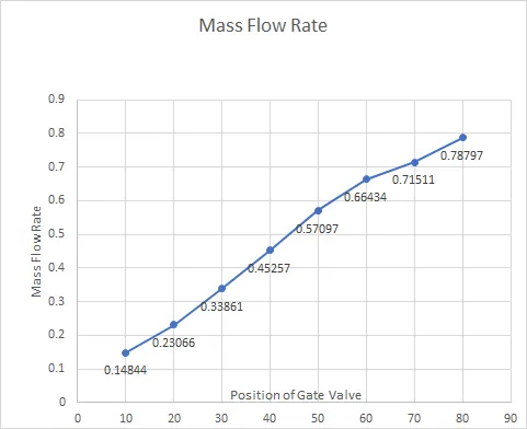
Mass Flow Rate (Kg/s) vs Position of Gate Valve (mm)
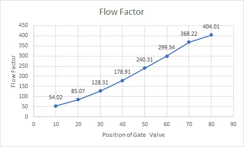
Flow Factor vs Position of Gate Valve (mm)
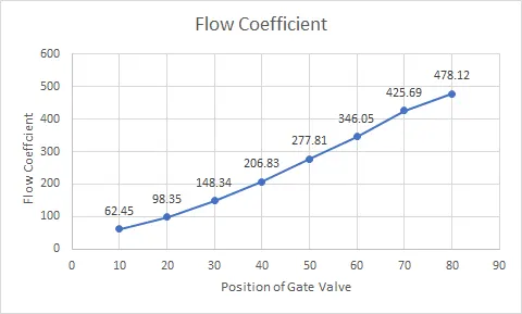
Flow Coefficient vs Position of Gate Valve (mm)
Mass Flow Rate (Kg/s) vs Flow Factor, Flow Coefficient
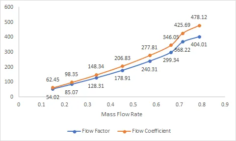
Conclusion
As the position of the gate valve is lifted
The mass flow rate increases
The Pressure drop decreases
With Drop in pressure, Flow Factor and Flow Coefficient increase which means that the Volume flow rate increases, resulting in more water passing through the valve