Ahmed Body Challenge
AIM
To find the drag coefficient of a Ahmed Body and the flow properties.
INTRODUCTION
The Ahmed Body was first created by S.R. Ahmed in his research
Since then, it has become a benchmark for aerodynamic simulation tools.
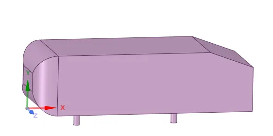
The simple geometrical shape has a length of 1.044 meters, height of 0.288 meters, and a width of 0.389 meters. It also has 0.5-meter cylindrical legs attached to the bottom of the body and the rear surface has a slant that falls off at 40 degrees.
GEOMETRY
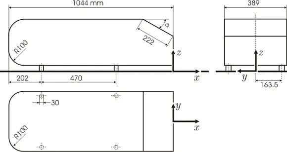
IMPORTANCE OF AHMED BODY
Ahmed Body is generic bluff body proposed to study the external aerodynamics of the vehicles.
The flow over the geometrically simple Ahmed reference body is used for the validation case for numerical simulations and it still continues a challenge numerical algorithms and turbulence modeling due to its complex three dimensional wake vortex interaction.
In their study, Ahmed and Ramm had noticed that the most of the drag from the body is due to pressure drag, which was generated near the rear side of the vehicle.
In the same paper, the authors observed that the strength of the flow separation in the vehicle is regulated by the slant angle.
PART 1
BASELINE CASE
Model Geometry
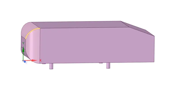
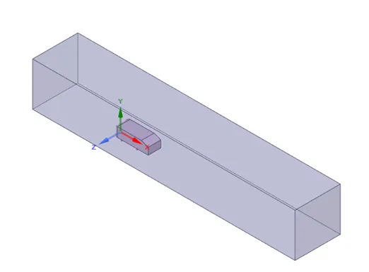
Adding Enclosure
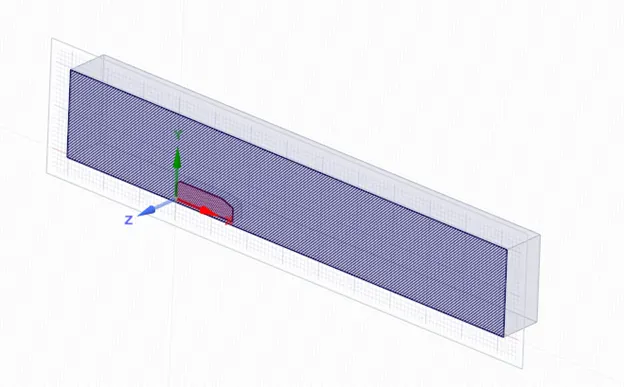
Cut Section
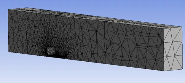
MESHING
Element size: 413.6 mm
Nodes: 16541
Elements: 83781
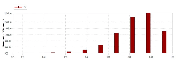
Mesh Quality
SOLVER SETUP
Type: Density based
Time: Steady
Energy equation: Enabled
Turbulence Model: Standard K-Epsilon
Inlet Velocity: 25 m/s
Outlet Gauge Pressure: 0
Initialization Method: Hybrid
POST PROCESSING
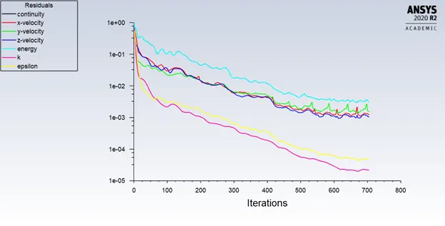
Residuals Plot
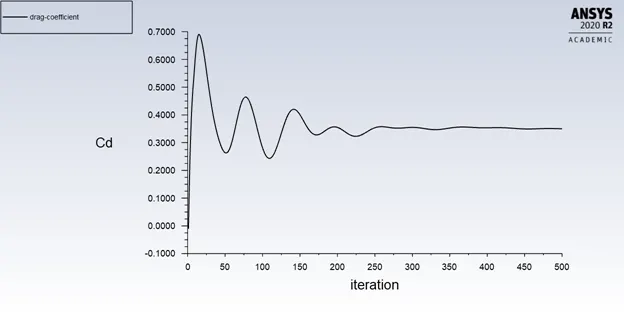
Drag Coefficient Plot
Drag Coefficient: 0.349
PART 2
REFINED MESH
Geometry
The Ahmed Body is added to spaceclaim
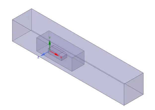
2 enclosures are added to the Ahmed Body
Enclosures are used to simulate wind tunnel testing
The Ahmed Body is split symmetrically using a section plane
MESHING
Multizone meshing
The external enclosure is subjected to multizone meshing
Element size: 0.1m
Maximum element size: 0.2m
Element Type: Hexa
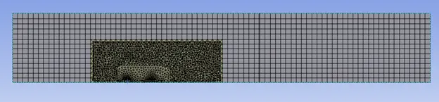
Body sizing
The inner enclosure is further refined
Element size: 0.05 mm
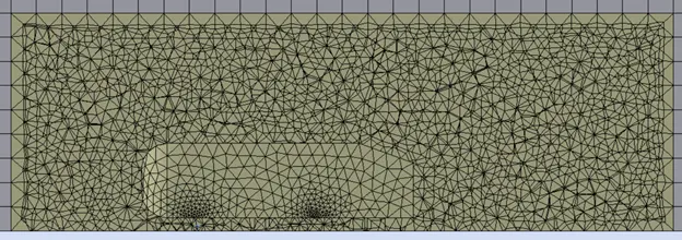
Inflation Layer
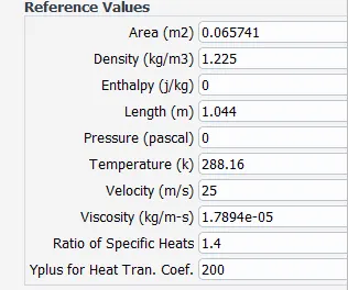
Reynolds Number, Re = ρ *V*L/μ
Density(ρ)= 1.225 kg/m3
Velocity (V) = 25 m/s
Length (L) = 1.044m
Dynamic Viscosity(μ) =1.7894 * 10^(-5 )
Re=`(1.225*25*1.044)/ 1.7894 * 10^-5 =1786772.10
Skin Friction Cf)= (2log(Re)-65)-2.3 = `(2Log〖(1786772.10)-65)〗^(-2.3)`= = 3.39 * 10-3
τwall=(Cf*ρ*V2)/2 = (3.39 * 10^(-3)*1.225*25^2)/2 = 1.297
Ufric= `√(τwall)/ρ) = √77.82/1.225 = 1.03
Inflation layer thickness =y+* μ/ Ufric * ρ = 200*1.7894 * 10-5/7.97*1.225= 2.86*10-3
Y+ is taken as 200. The acceptable value of Y+ for k-Epsilon turbulence model is 30-300.
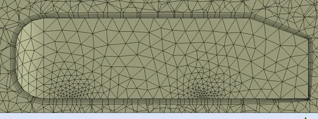
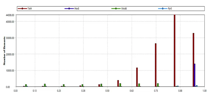
Mesh Details:
No of elements: 161157
Element Size: 0.1m
Solver Set up
Type: Density based
Time: Steady
Energy equation: Enabled
Turbulence Model: Standard K-Epsilon
Inlet Velocity: 25 m/s
Outlet Gauge Pressure: 0
Initialization Method: Hybrid
Results
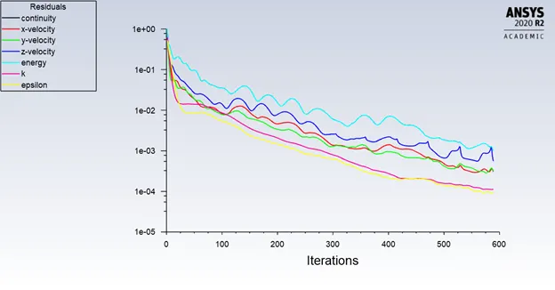
Residuals Plot
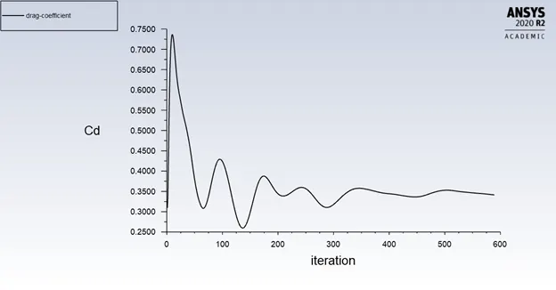
Drag Coefficient Plot
Drag Coefficient: 0.337
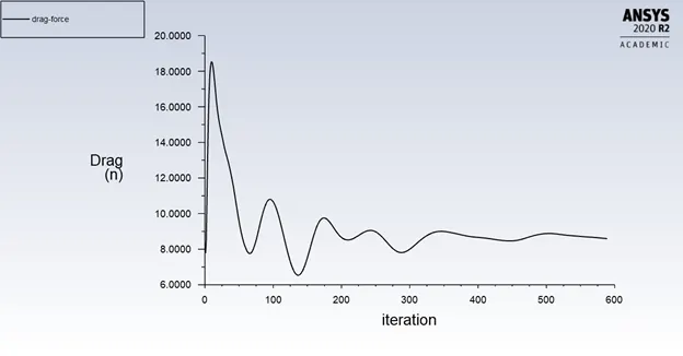
Drag Force Plot
Drag Force: 8.6 N
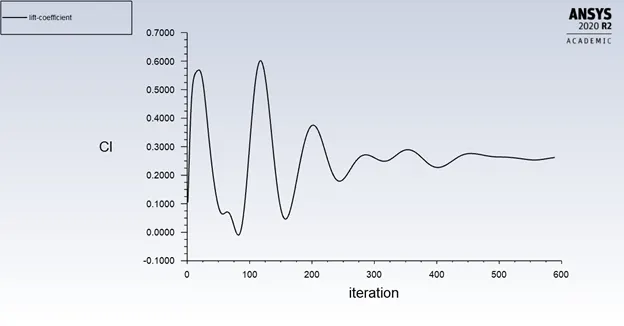
Lift Coefficient plot
Lift Coefficient: 0.262
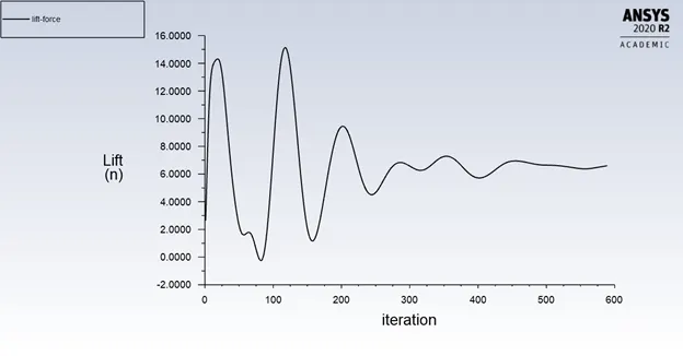
Lift Force Plot
Lift Force: 6.59 N
Enclosure
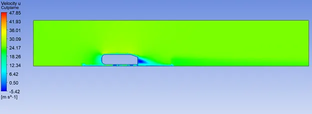
Velocity Contour
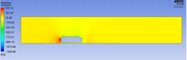
Pressure Contour
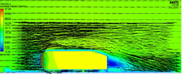
Velocity Vectors
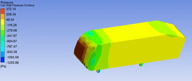
Car Wall
Pressure Contour
Grid Independence
No of elements: 276005
Element Size: .05m
Mesh Quality
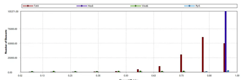
Results
Residuals Plot
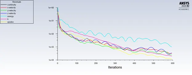
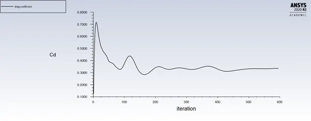
Drag Coefficient Plot
Drag Coefficient:0.334
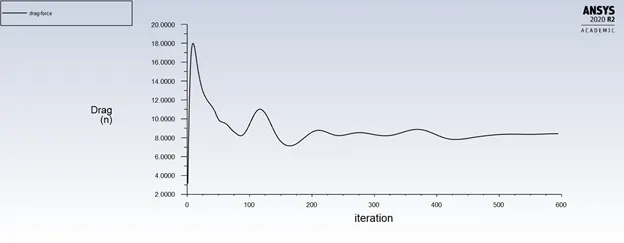
Drag Force Plot
Drag Force: 8.43 N
Lift Coefficient plot
Lift Coefficient: .239
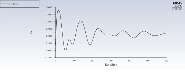
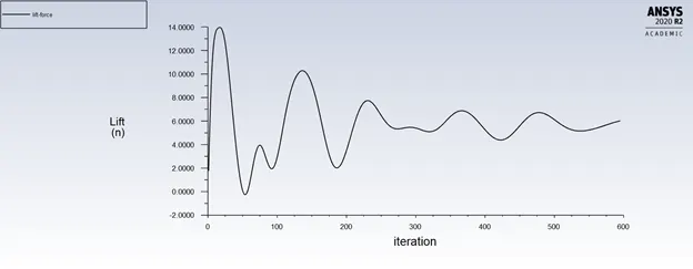
Lift Force Plot
Lift Force: 6.01 N
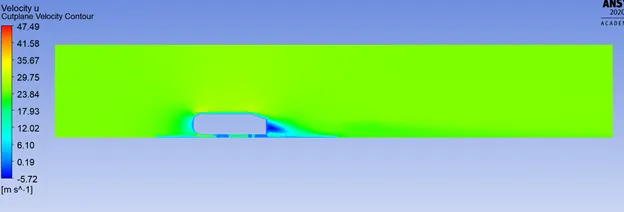
Enclosure
Velocity Contour
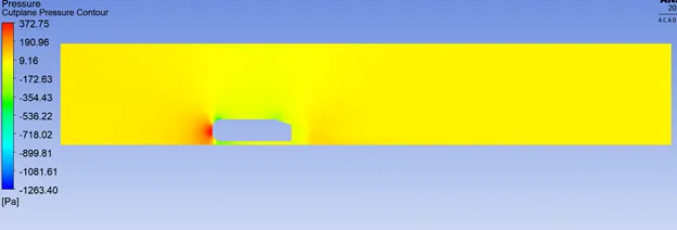
Pressure Contour
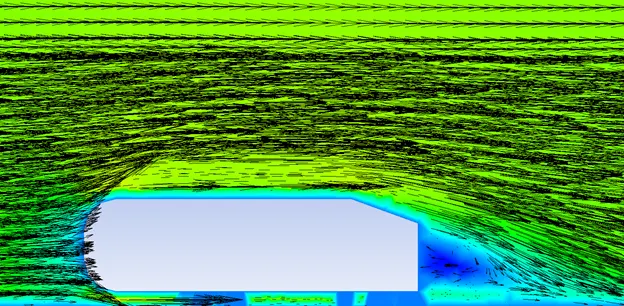
Velocity Vectors
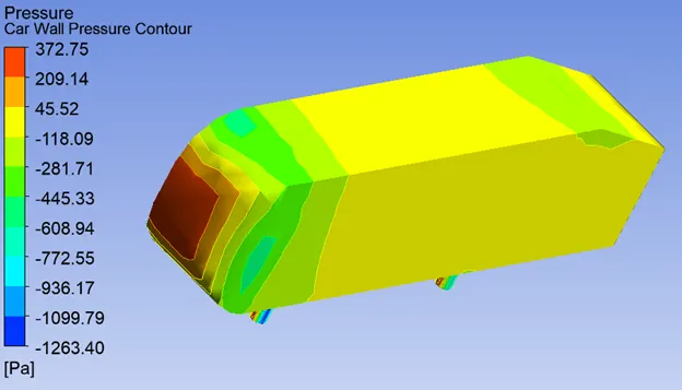
Car Wall
Pressure Contour
Case 2
No of elements: 640761
Element Size: 0.033 m
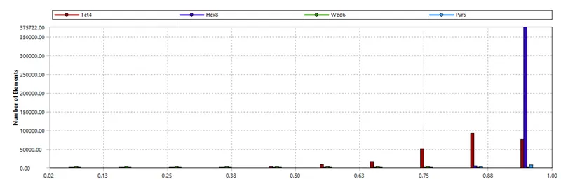
Mesh Quality
Results
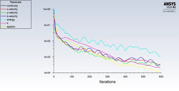
Residuals Plot
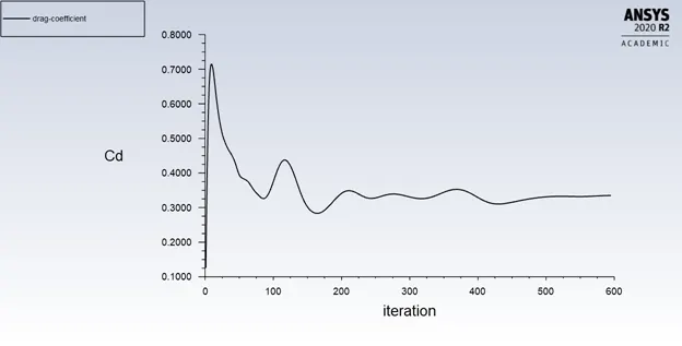
Drag Coefficient Plot
Drag Coefficient: 0.334
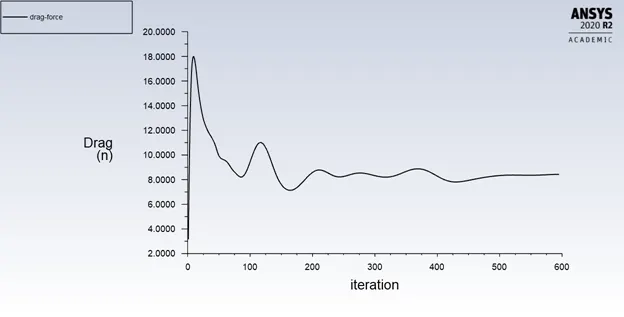
Drag Force Plot
Drag Force: 8.43 N
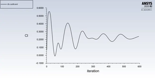
Lift Coefficient plot
Lift Coefficient: 0.239
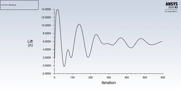
Lift Force Plot
Lift Force: 6.01
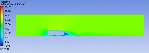
Enclosure
Velocity Contour
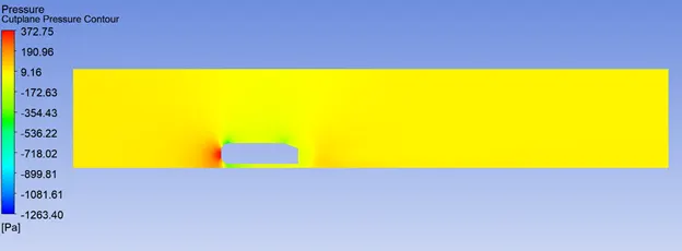
Pressure Contour
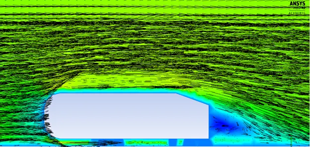
Velocity Vectors
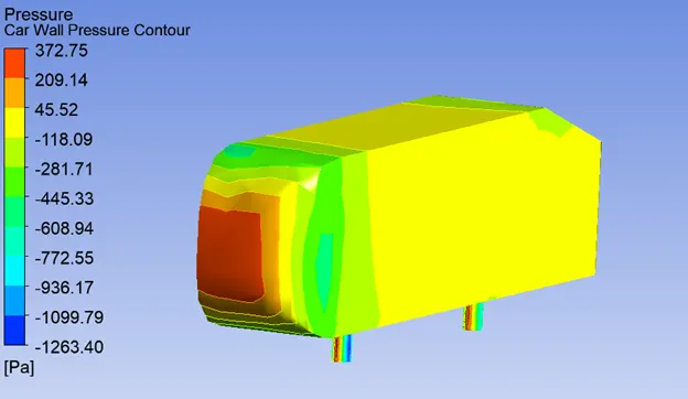
Car Wall
Pressure Contour
Grid Independence Study
|
Element Size |
No of Elements |
Drag Coefficient |
Drag Force(N) |
Lift Coefficient(N) |
Lift Force |
|
.1 |
161157 |
.337 |
8.6 |
6.59 |
.262 |
|
.05 |
276005 |
.334 |
8.43 |
6.01 |
.239 |
|
.033 |
640761 |
.334 |
8.43 |
6.01 |
.239 |
Conclusions
Seperation of flow
Flow separation or boundary layer separation is the detachment of a boundary layer from a surface into a wake.
Separation occurs after the flow goes through a region of low to high pressure differentia such as in the Front face of Ahmed Body
Flow separation results in reduced lift and increased pressure drag.
Negative Pressure
In the region ABC of the curved surface,
The area of flow decreases and hence the velocity increases. This means that flow gets accelerated in this region.
Due to the increase of the velocity, the pressure decrease in the direction of the flow