Week 9 - Parametric study on Gate valve.
AIMS : Aim of this challenge is to perfome a parametric study on the valve openings of a gate and understand the changes in mass flow rates , fow coefficient and flow factor of the flow.
OBJECTIVES : The main objectives of the challenge are :
1. To generate required volume for the simulation from given goemetry and extarct the parameteric distance from Space Cliam.
2. To generate a mesh required for simulation of the gate valve opening.
3. To perform the simulation and extract the mass flow rate, flow factor and flow coefficient terms .
4. To paramtrize the data from 10% to 80% of valve openings using the paramteric analysis section and plot the graphs.
THEORY :
A gate valve, also called sluice valve, often installed in a pipe fitting, opens by lifting a barrier called gate out of the path of the fluid. Gate valves require very little space along the pipe axis and hardly restrict the flow of fluid when the gate is fully opened. The gate faces can be parallel but are most commonly wedge-shaped.
Gate valves are used to shut off the flow of liquids rather than for flow regulation. When fully open, the typical gate valve has no obstruction in the flow path, resulting in very low flow resistance.
Formulation for the flow cofficient and flow factor:
Flow coefficient:
Flow coefficient is calculated using the expression:
`C_v= Q*sqrt((SG)/(DeltaP))`
Where, Q is Volumetric flow rate in Gallons per minute.
`DeltaP` is the pressure difference in psi.
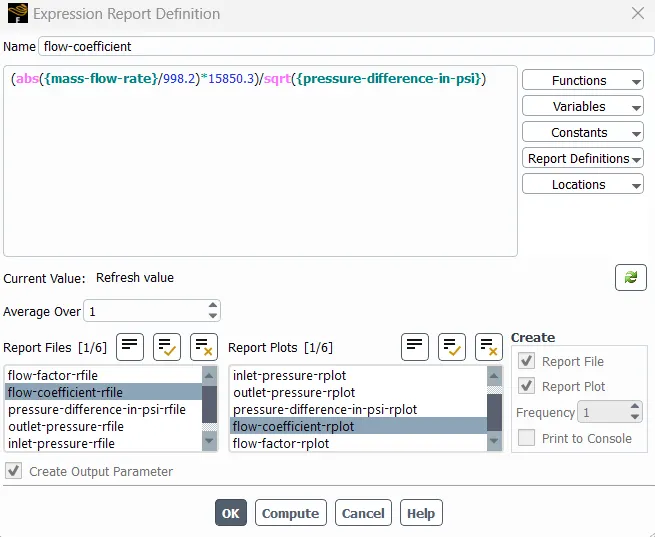
Mass flow rate has been converted to Gallon par minute using multiplication factor (15850.3/998.2) on mass flow rate(Kg/s)
SG is the specific gravity of fluid flowing, in this case its water, so its value is 1.
Flow factor:
low Factor is calculated using,
Kv=0.862⋅Cv">`K_v= 0.862*C_v`
Where,
Kv">`K_v` is the flow factor
Cv">`C_v` is the flow coefficient
SETUP
Initially the gate valve geometry was imported into space Claim and then using pull command the lengths of the pipes were increased to 800mm on both sides for development of the flow. Later using move command the valve has been moved up by 10mm distance and this valve variable is created a parameter for parametric analysis.
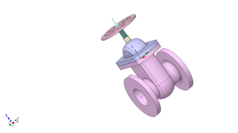
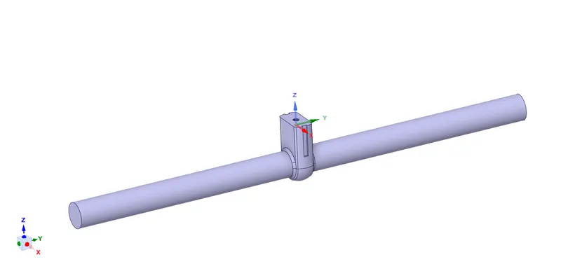
Now using volume extract command the required geometry for simulation has been extracted and the remaining parts were suppresed for physics.
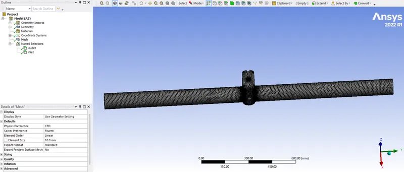
After importing this geometry to meshing an unstructured mesh with global cell size of 10mm has been generated and the inlet and outlet boundary were named using name selection option.
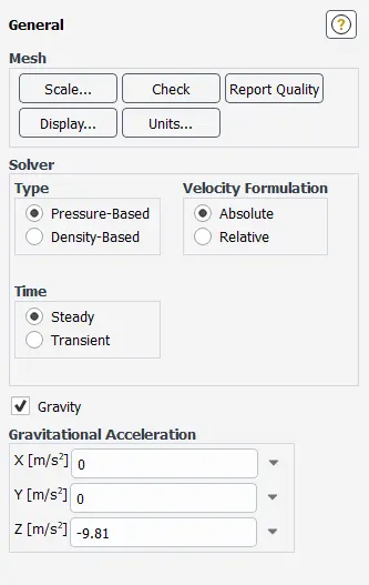
Now the mesh is imported into fluent and for the simulation in the gneral setup the gravity has been provided in netive Z direction.
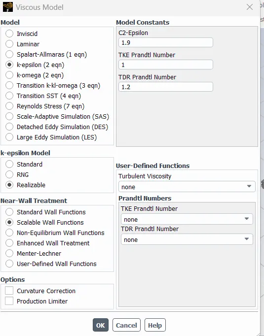
In model setup k-e turbluence model has been selected as this is turbuelnt with velocity of around 0.15 m/s . Reializable model is more accurate in predicting the results.
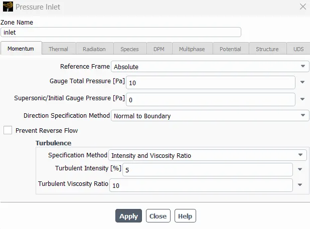
Later the inlet boundary condition is set to pressure inlet and the inlet pressure is given as 10Pa . The fluid used for the simulation is water.
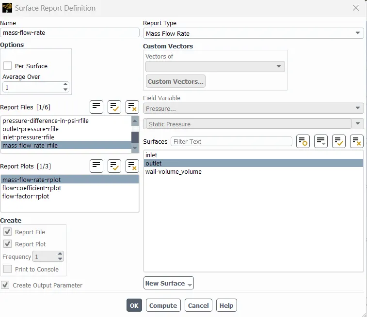
After settting up the major details the output parameters were set which are mass flow rate , flow coefficient and flow factor using report definitions section . The Methods were set to default and the simulation is intialized.
mass flow rate:
flow coefficient:
flow factor:
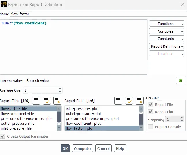
The simulation is converged with in 94 iterations and after the simulation the above metioned paramters were automatically extracted to the paramteric analysis table for the gate valve with valve opening of 10mm.
RESULTS
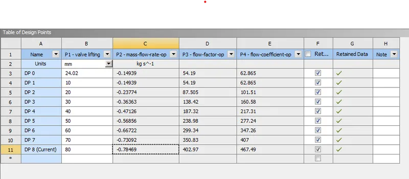
Now the simulation has to be perfomed for 20,30,40,50,60,70 anad 80mm . For that just updated the design points in that table runs the whole setup and provides the results. Once the results are obtained each and every case was set to current and cross checked and the geometry pictures captured at every valve opening case.
The Parametric Values Gatherd from the simulation are:
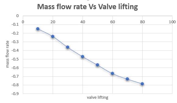
Mass Flow Rate vs Valve Opening:
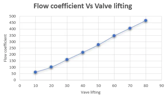
Flow Coefficient Vs Valve Opening:
Flow Factor Vs Valve Opening
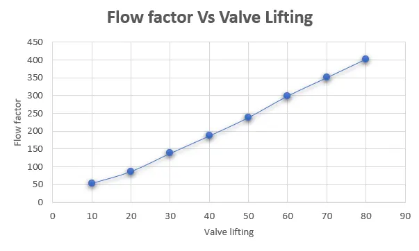
From theabove figures we can observe that with increase in the valve opening the masss flow rate at the outlet increased, same with flow coefficient and flow factor as they are directly related to mass flow rate.
CONCLUSIONS
1. With increase in the valve opening the mass flow rate , flow coeffcient and the flow factor incresases but in different magnitudes.
2. With increase in the valve opening the presssure difference decreases.