Week 9 - Parametric study on Gate valve.
AIM: To perform a parametric study on the gate valve simulation.
OBJECTIVE:
The aim of this project is to carry out a parametric study on the gate valve by setting the opening from 10% to 80% with the objective to:
- Obtain the mass flow rates at the outlet for each design point
- Calculate the flow coefficient and flow factor for each opening and plot the graph
- Discuss the results of the mass flow rate and flow coefficient
INTRODUCTION
Gate Valve
A gate valve is a valve that opens by lifting a barrier or gate out of the path of the fluid. Gate valves require very little space along the pipe axis and hardly restrict the flow of fluid when the gate is fully opened.
Uses:
Gate valves are used to shut off the flow of liquids rather than for flow regulation. When fully open, the typical gate valve has no obstruction over the fluid path, resulting in very low fluid resistance.
The size of the open flow path generally varies in a nonlinear manner as the gate is moved. This means that the flow rate does not change evenly with stem travel. Depending on the construction, a partially open gate can vibrate from the fluid flow.
Flow Coefficient
The flow coefficient of a device is a relative measure of its efficiency in allowing fluid flow. It describes the relationship between the pressure drops across an orifice valve or other assembly and the corresponding flow rate.
Mathematically the flow coefficient Cv(or flow-capacity rating of the valve) can be expressed as:
`Cv=Q√(SG)/(ΔP)`
where:
- Q is the rate of flow (expressed in US gallons per minute).
- SG is the specific gravity of the fluid (for water = 1).
- ΔP is the pressure drop across the valve (expressed in psi
In more practical terms, the flow coefficient Cv is the volume (in US gallons) of water at 60 °F that will flow per minute through a valve with a pressure drop of 1 psi across the valve.
Kv can be calculated from Cv using the equation:
`K v = 0.865 ⋅ C v`
Modeling Approach:
Pre-Processing:
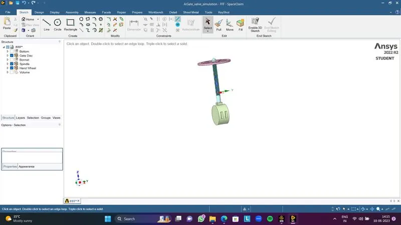
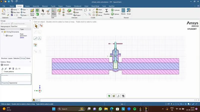
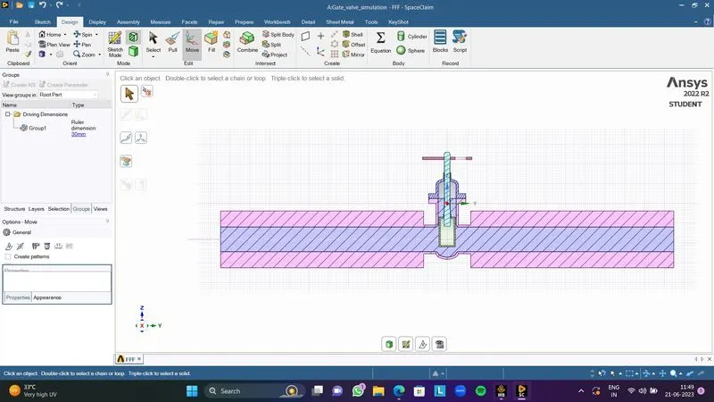
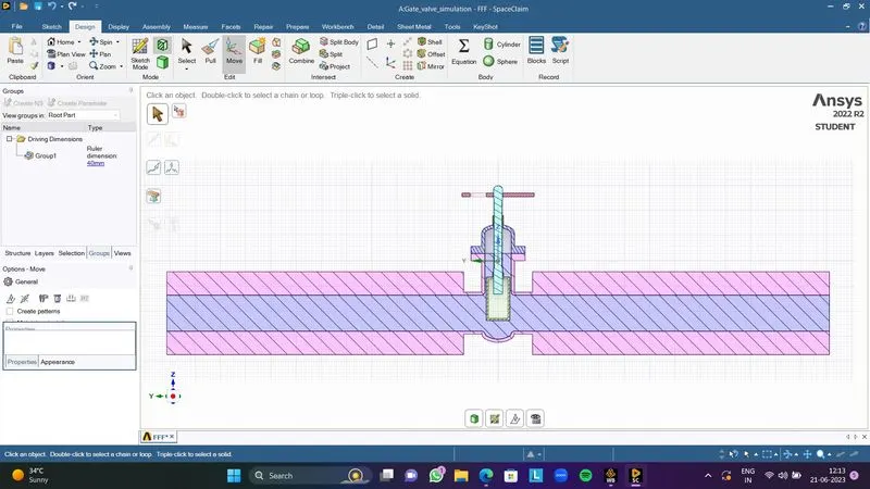
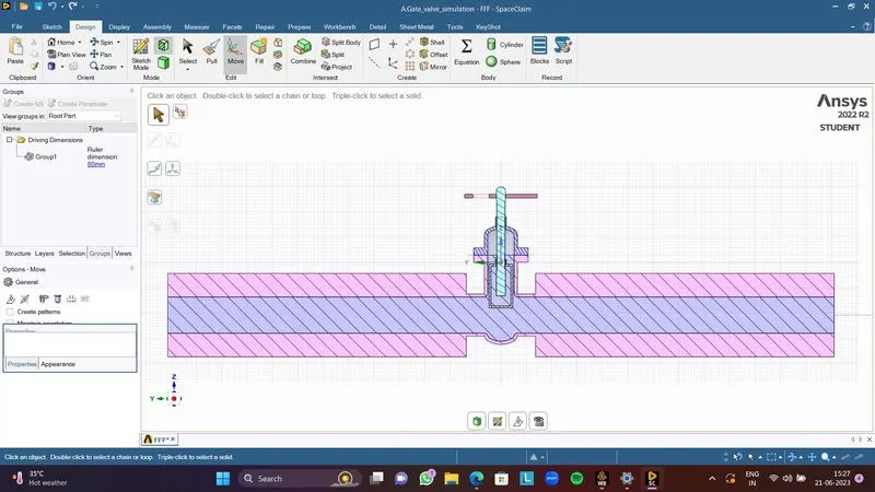
1. Importing geometry in SpaceClaim The following geometry was imported into SpaceClaim.
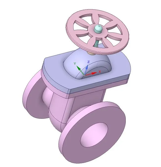
It has the following components:
- The bonnet is placed below the handwheel and prevents the splashing of fluid from the upper region.
- Handwheel and spindle that can be used to lift or lower the gate disc.
- The gate disc is attached to the spindle at the bottom.
- The bottom is a casing that covers the gate disc and the water flows through it. Two ports serve as an inlet and outlet for the fluid.
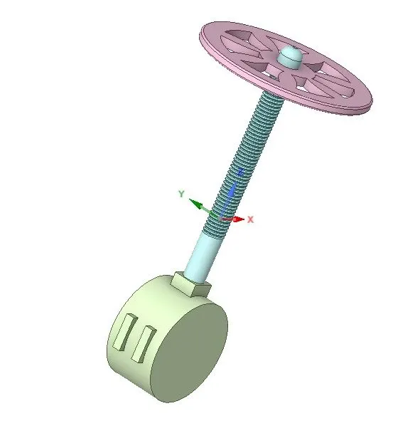
Geometry Preparation:
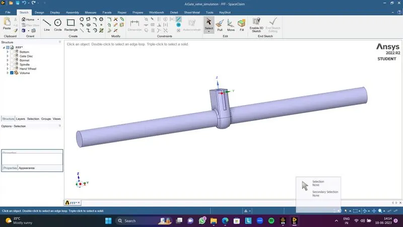
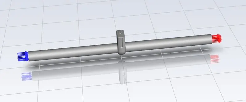
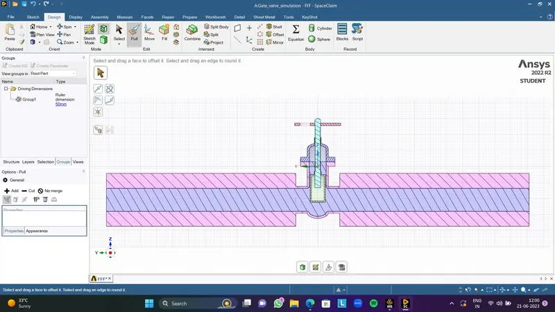
First, we extend the geometry of the inlet and outlet ports by 800 mm each. It will look as shown below.
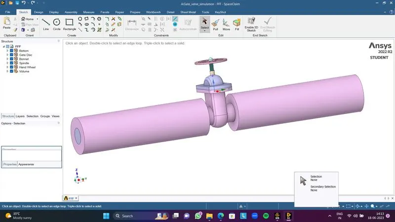
After extension, create Fluid volume by selecting the inlet, outlet and upper edges of the “Bottom” part. The creation of fluid volume is shown below:
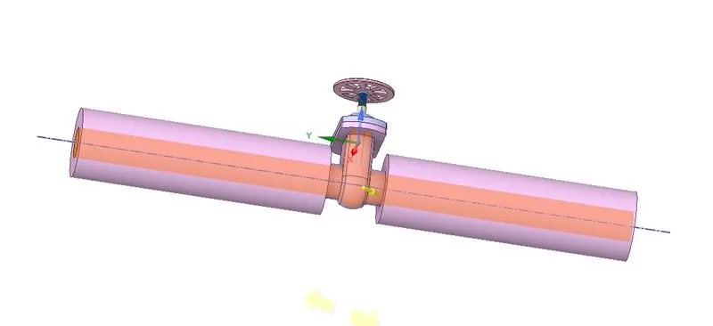
After generating fluid volume, hide all parts and suppress them for physics
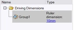
To simulate the effect of the stopper on the mass flow rate of the fluid at the outlet the stopper is moved 10mm in the positive Z-direction so that the flow path is partially open. This is parametrized. The parameterization helps us change its value and compute the required output parameters without having to repeat the same processes again. Since we are not interested in the analysis of solid geometry, it is suppressed.
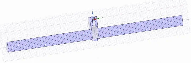
Sectional View:
MESHING:
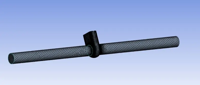
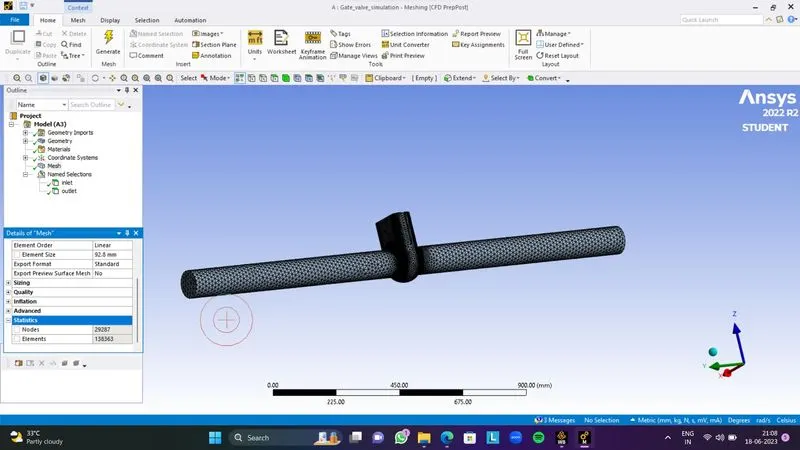
Named Selection has been given to each side as Inlet & outlet.
Setting Up Physics:
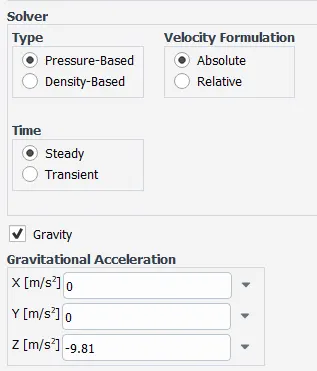
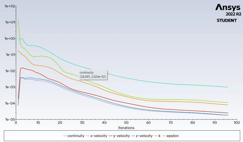
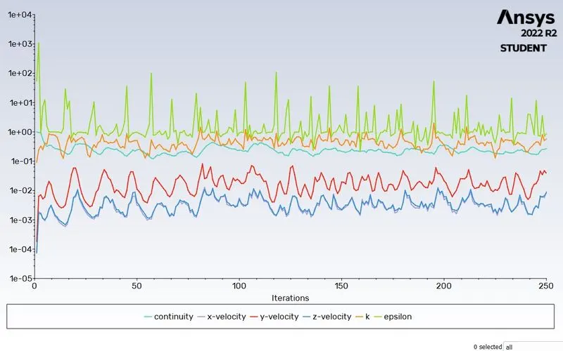
First of all the mesh is set up and the solver is defined as below:
Solver Type: Pressure-Based Solver
Gravity: -9.81 m/s2 (in the negative z-direction)
Solver: Steady State
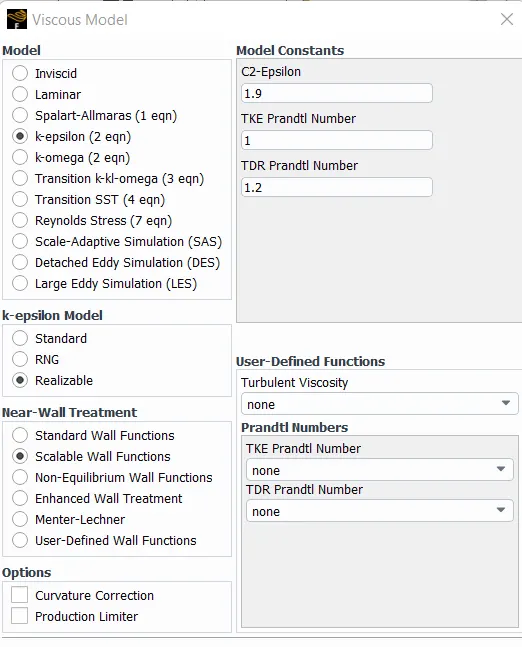
Model: k-epsilon model (realizable with scalable wall function)
Material: Water
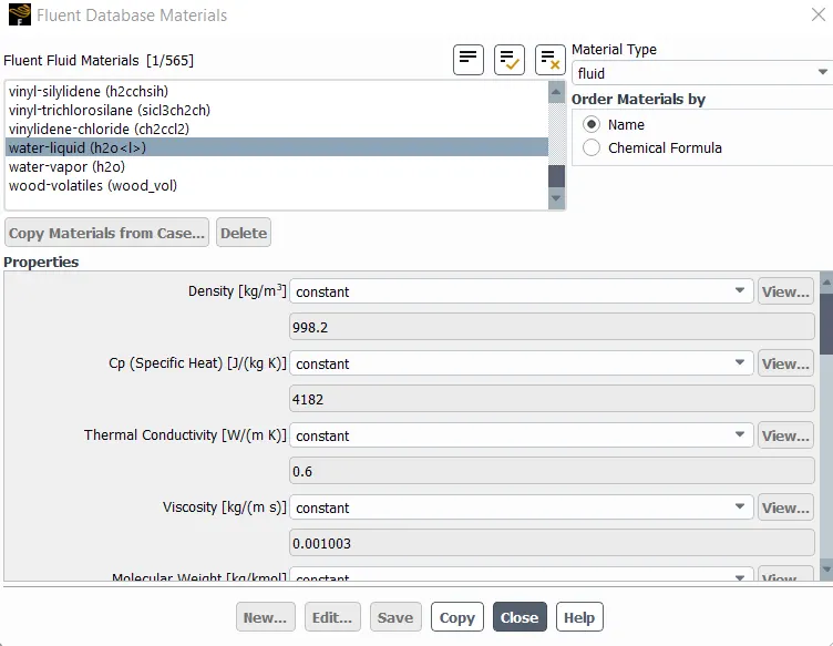
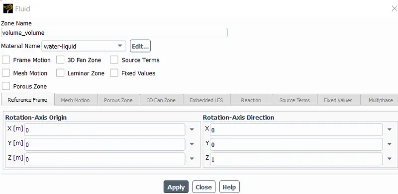
Cell Zone: Fluid(water)
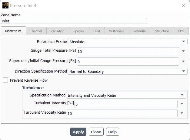
Inlet Boundary Condition: Pressure Inlet (10Pa)
Outlet Boundary Condition: Pressure Outlet
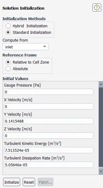
The model will be initialized with standard initialization and the data will be computed from the inlet.
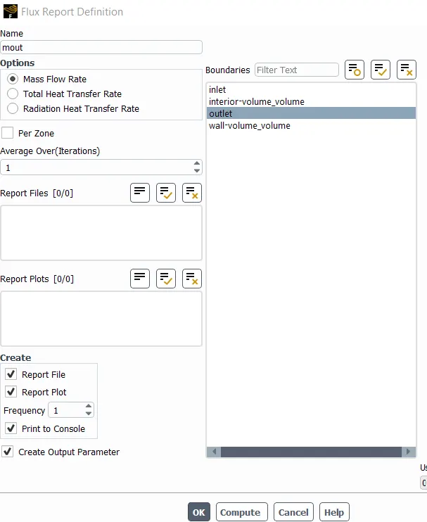
Flux parameter is included for mass flow rate at outlet.
Case 1: 10mm Lift
Results:
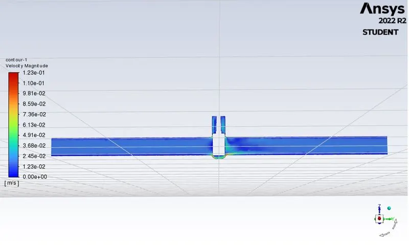
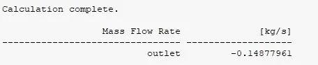
`C v = Q √ ( S G) /(Δ P )`
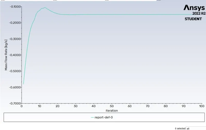
Mass flow rate =0.14877961 kg/sec ( 1kg/sec=15.85 gal/min )
Q = 2.35815682 gal/min.
SG (specific gravity) for water =1
ΔP = Pressure at inlet - pressure at outlet = 10 pa , ( 1pa =0.000145psi )
ΔP =0.00145 psi.
Flow Co-efficient, C_V = 2.3581*26.261=61.926
Flow Factor, K_V = 0.865 * 61.926=53.5699
Case 2: 20mm Lift
Results:
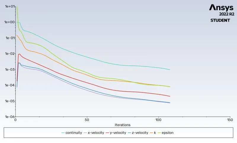
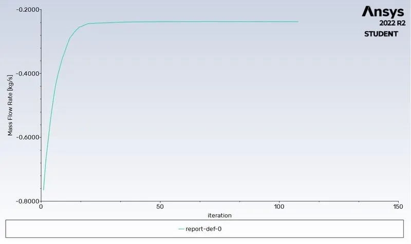
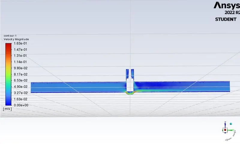
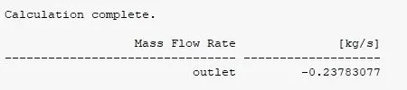
Mass flow rate =0.23783077 kg/sec ( 1kg/sec=15.85 gal/min )
Q = 3.7696177045 gal/min.
SG (specific gravity) for water =1
ΔP = Pressure at inlet - pressure at outlet = 10 pa , ( 1pa =0.000145psi )
ΔP =0.00145 psi.
Flow Co-efficient, C_V = 3.7696177045*26.261=98.993
Flow Factor, K_V = 0.865 * 98.9939305378745 = 85.629
Case 3: 30mm Lift
Results:
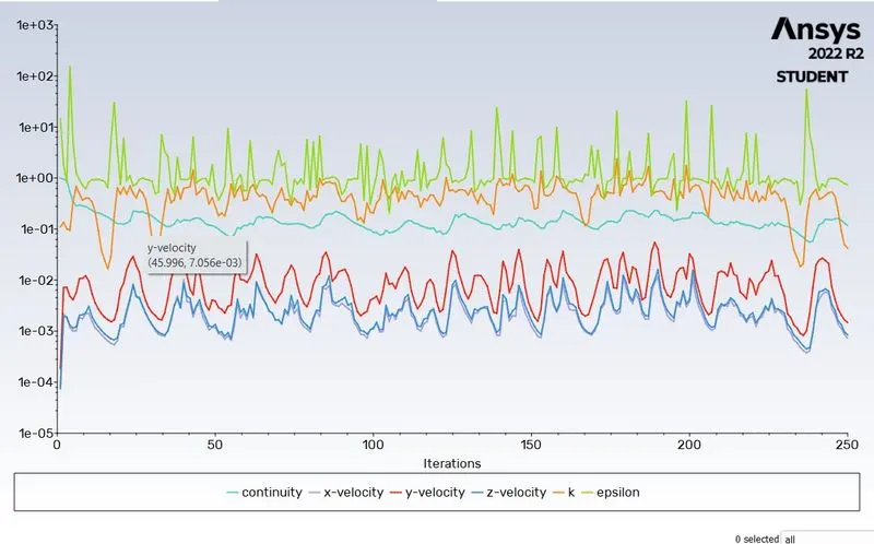
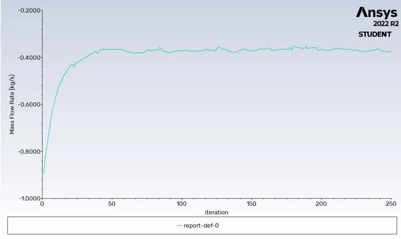
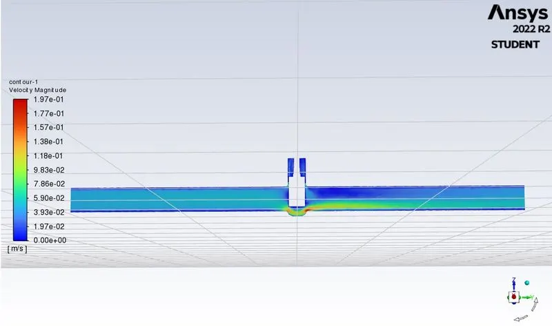
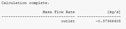
Mass flow rate =0.37366405 kg/sec ( 1kg/sec=15.85 gal/min )
Q = 5.9225751925 gal/min.
SG (specific gravity) for water =1
ΔP = Pressure at inlet - pressure at outlet = 10 pa , ( 1pa =0.000145psi )
ΔP =0.00145 psi.
Flow Co-efficient, C_V = 5.9225751925*26.261=155.532
Flow Factor, K_V = 0.865 * 155.5327471302425 = 134.535
Case 4: 40mm Lift
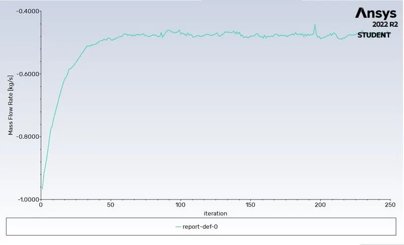
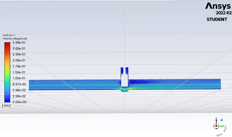
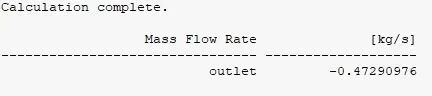
Mass flow rate =0.47290976 kg/sec ( 1kg/sec=15.85 gal/min )
Q = 7.495619696 gal/min.
SG (specific gravity) for water =1
ΔP = Pressure at inlet - pressure at outlet = 10 pa , ( 1pa =0.000145psi )
ΔP =0.00145 psi.
Flow Co-efficient, C_V = 7.495619696*26.261=196.842
Flow Factor, K_V = 0.865 * 196.842468836656 = 170.268
Case 5: 50mm Lift
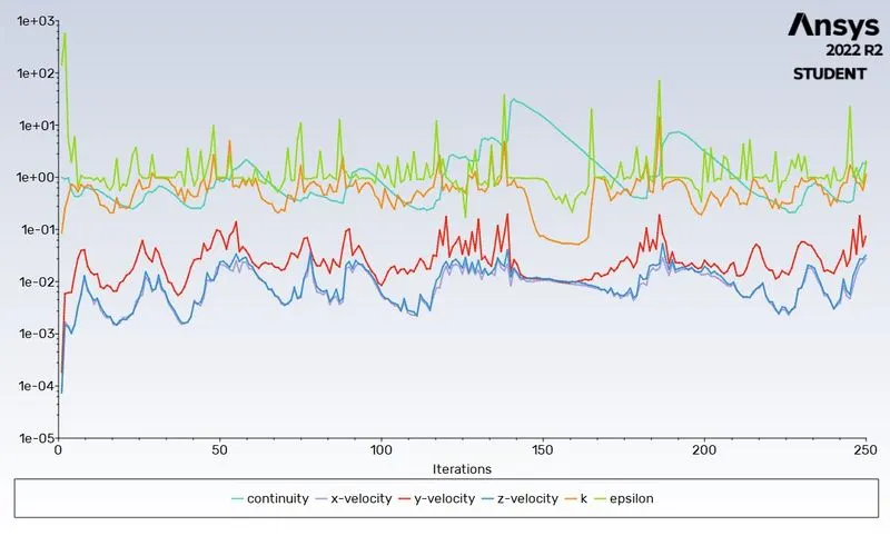
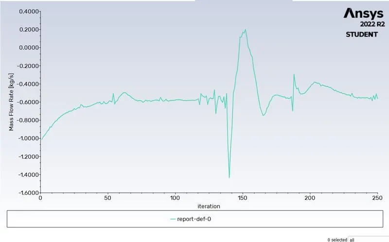
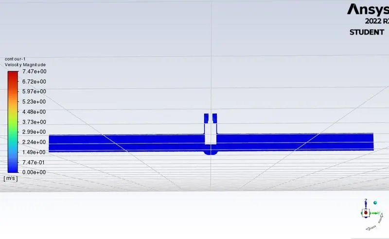
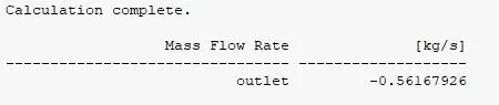
Mass flow rate =0.56167926 kg/sec ( 1kg/sec=15.85 gal/min )
Q = 8.902616271 gal/min.
SG (specific gravity) for water =1
ΔP = Pressure at inlet - pressure at outlet = 10 pa , ( 1pa =0.000145psi )
ΔP =0.00145 psi.
Flow Co-efficient, C_V = 8.902616271*26.261=233.791
Flow Factor, K_V = 0.865 * 233.791605892731 = 202.229
Case 6: 60 mm Lift
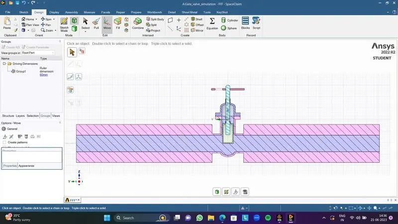
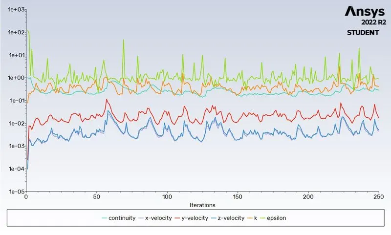
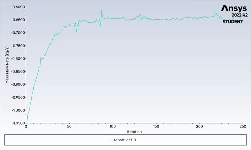
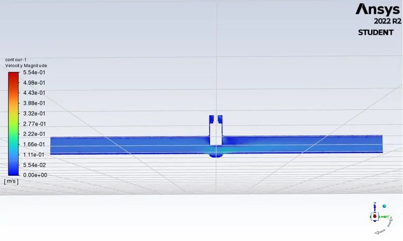
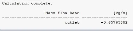
Mass flow rate =0.65765882 kg/sec ( 1kg/sec=15.85 gal/min )
Q = 10.423892297 gal/min.
SG (specific gravity) for water =1
ΔP = Pressure at inlet - pressure at outlet = 10 pa , ( 1pa =0.000145psi )
ΔP =0.00145 psi.
Flow Co-efficient, C_V = 10.423892297*26.261=273.741
Flow Factor, K_V = 0.865 * 273.741835611517 =236.786
Case 7: 70 mm Lift
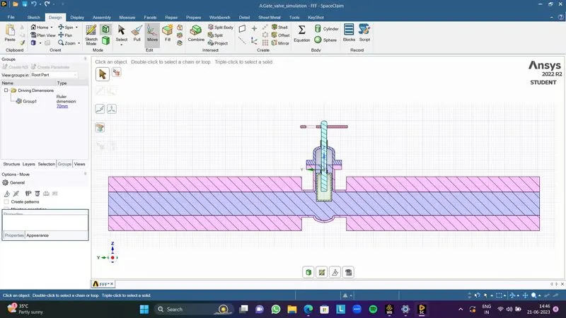
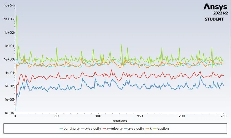
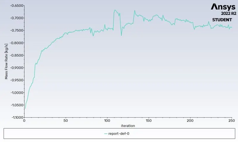
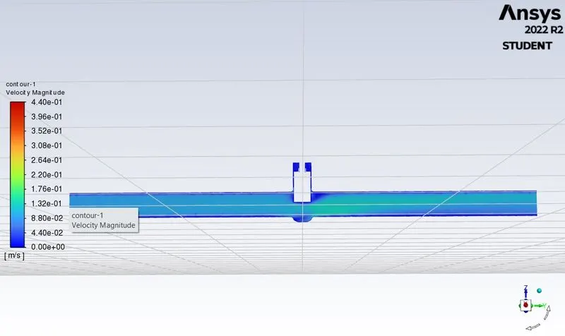
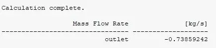
Mass flow rate =0.73859242 kg/sec ( 1kg/sec=15.85 gal/min )
Q = 11.706689857 gal/min.
SG (specific gravity) for water =1
ΔP = Pressure at inlet - pressure at outlet = 10 pa , ( 1pa =0.000145psi )
ΔP =0.00145 psi.
Flow Co-efficient, C_V = 11.706689857*26.261=307.429
Flow Factor, K_V = 0.865 * 307.429382334677 =265.926
Case 8: 80 mm Lift
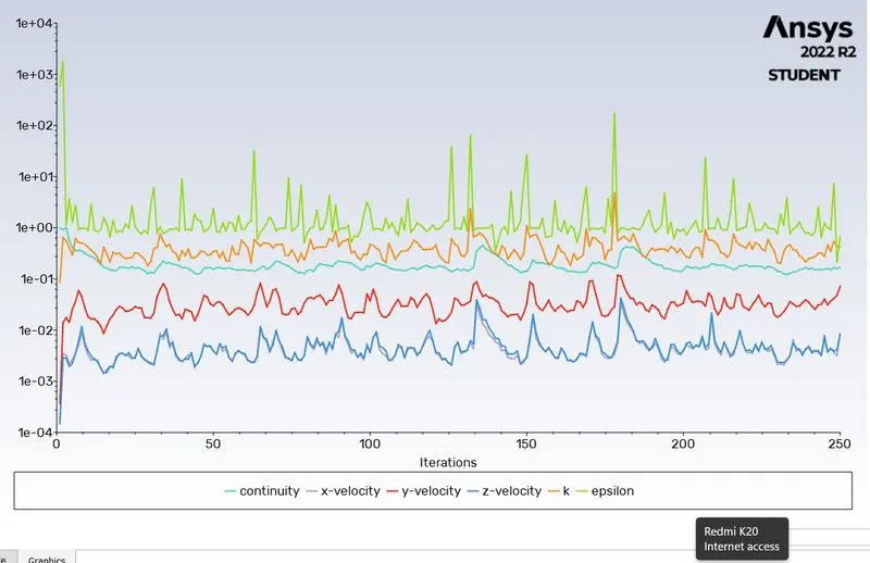
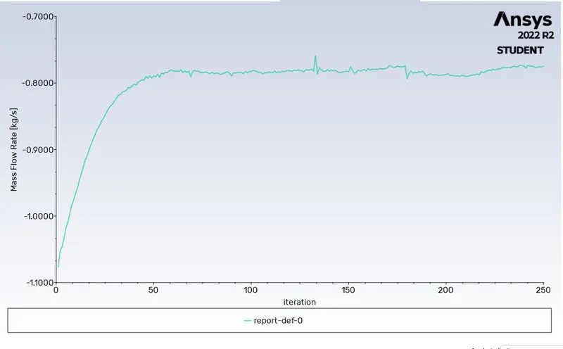
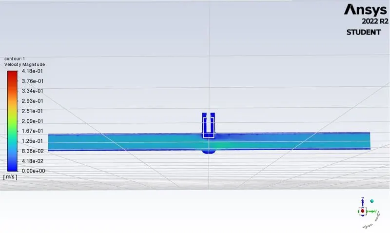
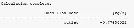
Mass flow rate =0.77456022 kg/sec ( 1kg/sec=15.85 gal/min )
Q = 12.276779487 gal/min.
SG (specific gravity) for water =1
ΔP = Pressure at inlet - pressure at outlet = 10 pa , ( 1pa =0.000145psi )
ΔP =0.00145 psi.
Flow Co-efficient, C_V = 12.276779487*26.261= 322.400
Flow Factor, K_V = 0.865 * 322.400506108107 =278.876
Mass Flow Rate :
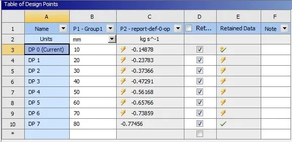
| CASES | LIFT | MASS FLOW RATE | FLOW COEFFICIENT | FLOW FACTOR |
| 1 | 10 mm | -0.14878 | 61.926 | 53.5699 |
| 2 | 20 mm | -0.23783 | 98.993 | 85.629 |
| 3 | 30 mm | -0.37366 | 155.532 | 134.535 |
| 4 | 40 mm | -0.47291 | 196.842 | 170.268 |
| 5 | 50 mm | -0.56168 | 233.791 | 202.229 |
| 6 | 60 mm | -0.65766 | 273.741 | 236.786 |
| 7 | 70 mm | -0.73859 | 307.429 | 265.926 |
| 8 | 80 mm | -0.77456 | 322.400 | 278.876 |
Observation:
1. The negative mass flow rate at the outlet indicates that the fluid is flowing out of the system.
2. The mass flow rate increases with an increase in the lift of the spindle.
3. The flow factor and flow coefficient are proportional to each other.
Conclusion:
The flow of water through a gate valve at different design points is accurately simulated using a parametric study. The values of the mass flow rate at the outlet are also calculated and analyzed for all the design points.