Week 9 - Parametric study on Gate valve.
To perform a parametric study on the gate valve simulation by setting the opening from 10 % to 80%.
Objective
- Obtain the mass flow rates at the outlet for each design point.
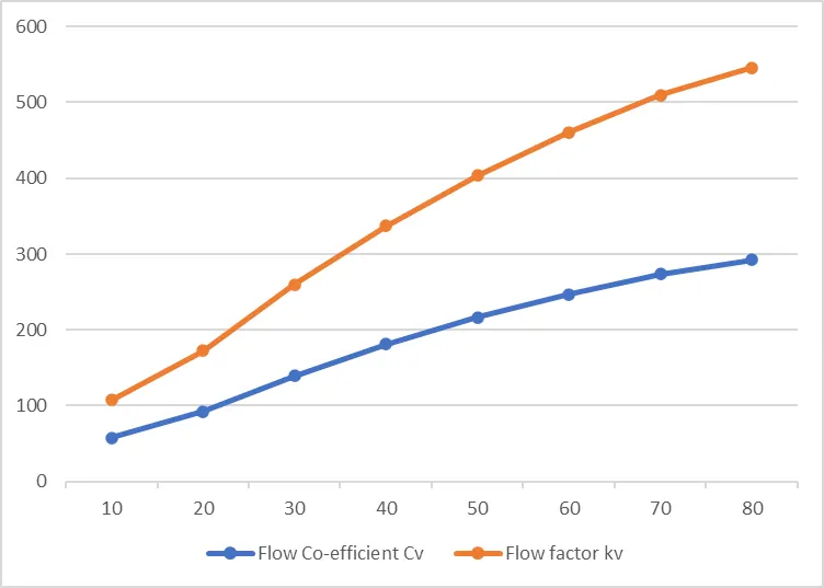
- Calculate the flow coefficient and flow factor for each opening and plot the graph.
- Discuss the results of the mass flow rate and flow coefficient.
Introduction
Gate valves are used in fluid pipelines to control the flow of fluid or An on-off valve that works by inserting a rectangular gate or wedge into the flow of the fluid. The gate or wedge is there that controls the flow of fluid. A wedge of the gate or shape of the gate is of different shapes they may be circular or rectangular plate-shaped.
Gate valves are used to shut off the flow of liquids rather than for flow regulation, which is frequently done with a globe valve. When fully open, the typical gate valve has no obstruction in the flow path, resulting there is no flow resistance(Comparatively minimum). The size of the open flow path generally varies in a nonlinear manner as the gate is moved. This means that the flow rate does not change evenly with stem travel. A partially open gate can vibrate from the fluid flow depending on the construction. Gate valves are primarily used with larger pipe diameters (from 2" to the largest pipelines) since they are less complex to construct than other types of valves in large sizes. At high pressures, friction can become a problem. As the gate is pushed against its guiding rail by the pressure of the medium, it becomes harder to operate the valve. Large gate valves are sometimes fitted with a bypass controlled by a smaller valve to be able to reduce the pressure before operating the gate valve itself.
Gate valves without an extra sealing ring on the gate or the seat are used in applications where minor leaking of the valve is not an issue, such as heating circuits or sewer pipes.
Valve construction
Common gate valves are actuated by a threaded stem that connects the actuator (e.g. handwheel or motor) to the gate. They are characterised as having either a rising or a non-rising stem, depending on which end of the stem is threaded. Rising stems are fixed to the gate and rise and lower together as the valve is operated, providing a visual indication of valve position. The actuator is attached to a nut that is rotated around the threaded stem to move it. Nonrising stem valves are fixed to, and rotate with the actuator, and are threaded into the gate. They may have a pointer threaded onto the stem to indicate valve position since the gate's motion is concealed inside the valve. Non-rising stems are used where vertical space is limited.
Gate valves may have flanged ends drilled according to pipeline-compatible flange dimensional standards.
Gate valves are typically constructed from cast iron, cast carbon steel, ductile iron, gunmetal, stainless steel, alloy steel, and forged steel.
All-metal gate valves are used in ultra-high vacuum chambers to isolate regions of the chamber
Parts of Gate Valve
- Body
- Bonnet
- Disc
- Seat
- Stem and
- Actuators
Body
The valve body is the main pressure-retaining part, which also holds other parts named disc and stem. This also provides passage to flow from the valve, its end connection is piping this end can be but welding type, threaded, and many more depending upon the size and pressure of the piping system. The valve body can be cast, or forged in different materials such as cast steel, stainless steel, and alloy steel depending upon the requirement.
Bonnet
It is the second pressure-retaining part of the valve. It is also called a cover. We can connect it to the system by bolting, welding, or threading to create a valve enclosure. In the case of the gate, stop, and diaphragm wall it has an opening so that the valve stream and pass through it. Bonded provides access to valve internals during maintenance.
Disc
This is is the part that allows throttles or stops flow on its position. In the case of a plug or ball valve, the disk is called a plug or ball. A disc is seated against the stationary wall seat or seats when the wall is in the closed position. It can be moved away from the valve seat by the motion of the valve string which the exception of the check valve and safety relief valve in which the disc is moved away from its seat by the fluid flow and pressure.
Seat
This is one of the main components of the system which directly affects the leakage rate of the valve. One of the integrals to the valve body is made up of forged metallic rings or non-metallic rings. All valves may have one or more seats. In the case of the globe and swing check valve, there is one seat. The gate valve has two seats, one on the upstream side and the other on the downstream side. Multipod clubs and ball valves may have several seats. Depending upon the number of ports on the valve or plug.
Stem
Stem is a forged solid rod or shaft. The valve steam transferred the required motion of the disc plug or valve for opening and closing of the valve. The stem is connected to the valve handwheel at one end and the valve disc on the other side. In the gate for the globe valve linear motion of the disk opens or closes the valve. While in plug, ball, butterfly valve disc is not located to open or close the valve. Note that stop check valves or check valve does not have a stem.
Actuators
The actuator is a mechanism that operates the valve. It is connected to the stem and disc assembly. It may be manually operated by a handwheel, manual lever, gear, or chain or it can be operated through a motor and solenoid. Many other common parts of the gate valve are gland flange, stem nut, handwheel, slud nuts, bonnet gasket, and many more.
STEPS TO BE FOLLOWED
A parameter is defined as a numerical or other measurable factor forming one of a set that defines a system or sets of conditions of its operation. Parameters are elements of a system that are useful or critical to identifying a system or evaluating a system’s performance, status, or condition. As an example, parameters of an equation modelling movement could include the mechanics, masses, dimensions and shapes, and densities and viscosities of fluids within the system.
A parametric analysis, also known as a sensitivity analysis, is the study of the influence of different geometric or physical parameters or both on the solution of the problem. Parametric analysis is an important tool for design exploration hear gate opening is the parameter and retained value will be the mass flow rate.
Step 1:
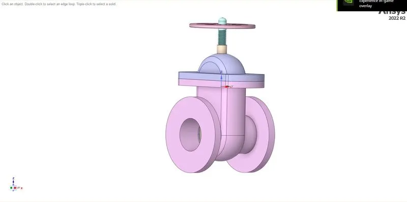
Initially, start with importing the geometry to the Ansys workbench
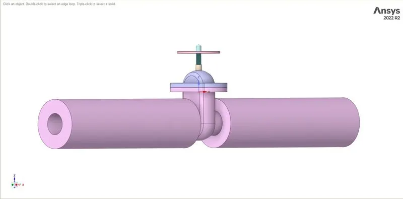
Use the pull tool to create a pipe from the flange to capture all the results because the extended fluid region helps to give more accurate results
After that make gate valve movement in the z-axis and create it as a parameter by Group->parameter
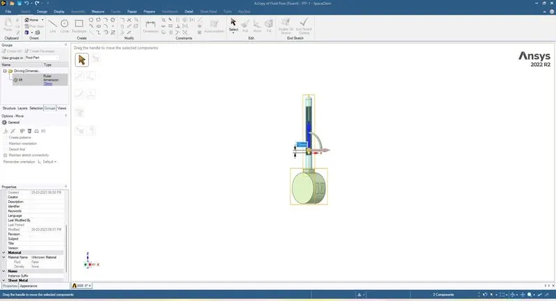
Then extract the fluid volume and suppress all other body
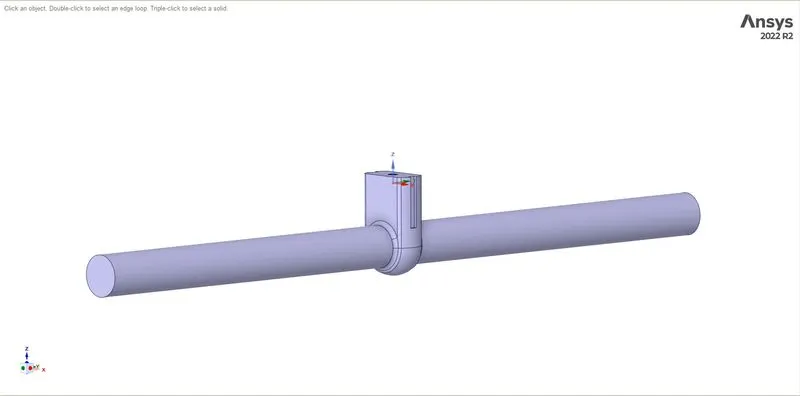
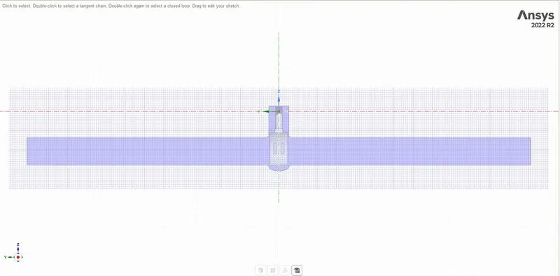
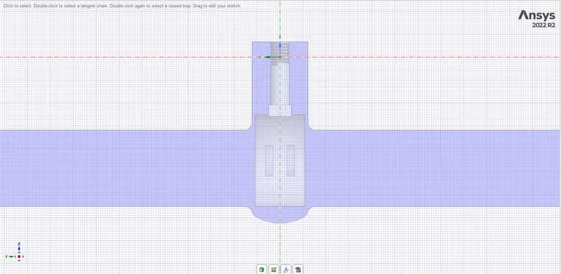
Step 2: From the geometry create a mesh with tetra elements with an element size of 6 mm. and name the components and export them to the solver.
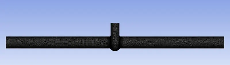
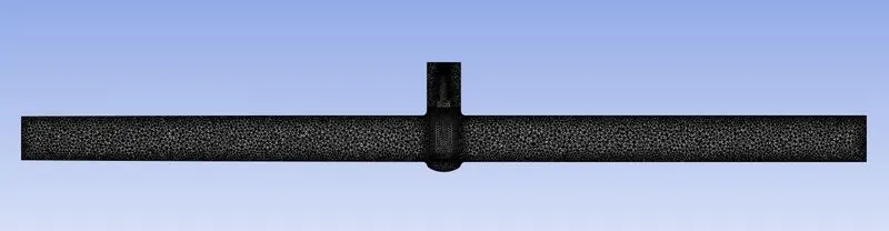
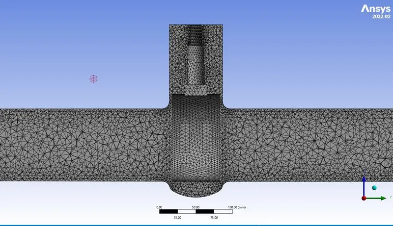
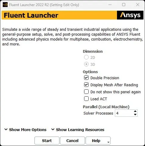
Step 3:In this step, the meshed geometric file has been imported to the fluent module and set the following conditions as follows in the fluent in solving the problem.
This procedure is followed in Ansys fluent
|
SOLVER TYPE |
Pressure based |
|
VELOCITY FORMULATION |
Absolute |
|
TIME |
Steady-state |
|
Gravity |
Applied in the negative z-direction |
|
VISCOUS MODEL |
K epsilon realisable with enhanced wall function |
|
MATERIAL |
Fluid: Water |
|
CELL ZONES |
Fluid flow |
|
Inlet |
Pressure inlet 10 pa |
| Outlet | Pressure outlet |
| Outlet parameter | Mass flow rate |
the hybrid scheme is used for the initialization
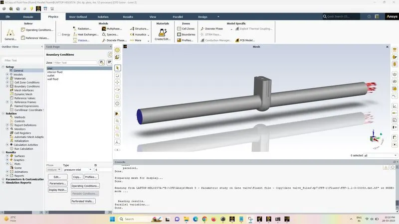
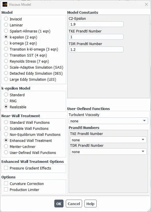
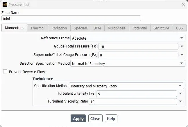
Solution->definition->mass flow rate t and click the check box to create the output parameter and we can easily get the mass flow rate in the parameter set.
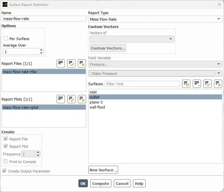
Before updating the parameter set make sure that they retain the check box that has been clicked.
Results
apart from the parametric output we can able to get each result separately by changing the current design point with the help of a set as the current design point option.
case 1:Valve opening=10%
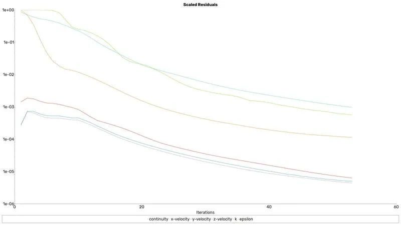
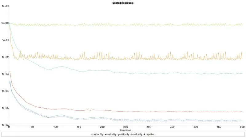
Residuals
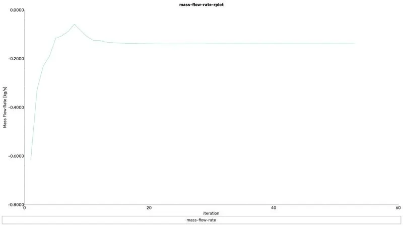
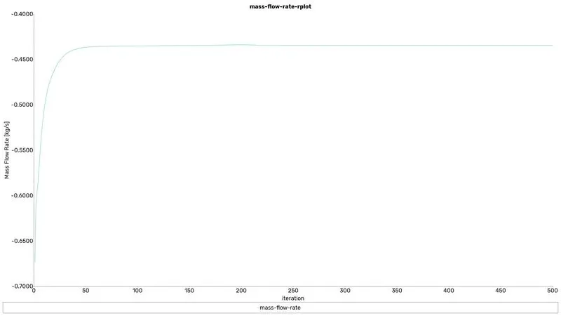
Mass flow rate
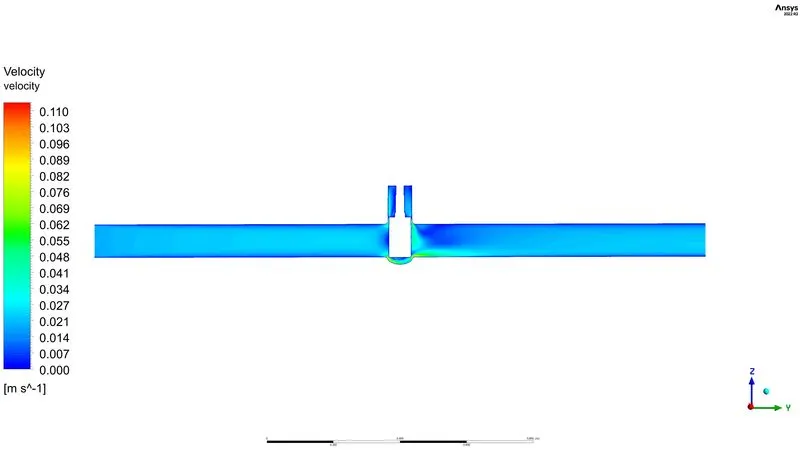
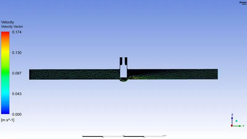
Velocity contour
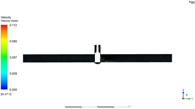
Velocity Vector
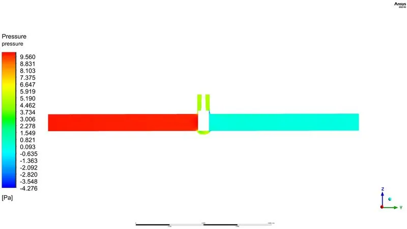
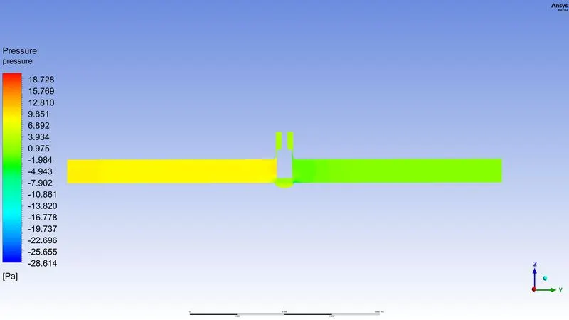
Pressure contour
case 2:Valve opening=20%
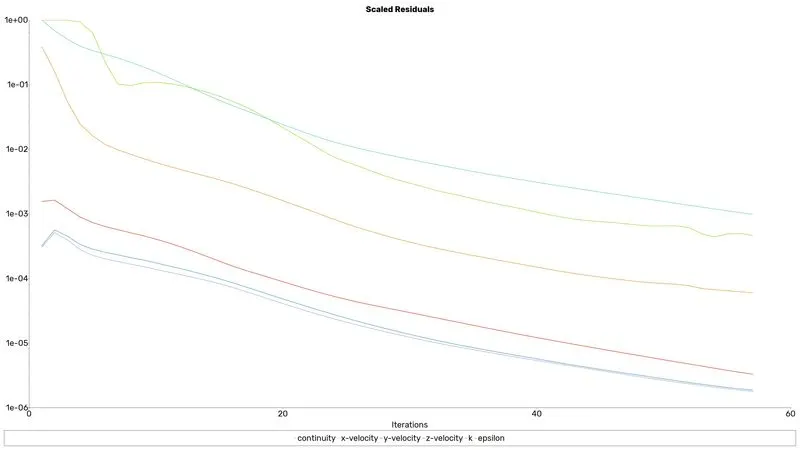
Residuals
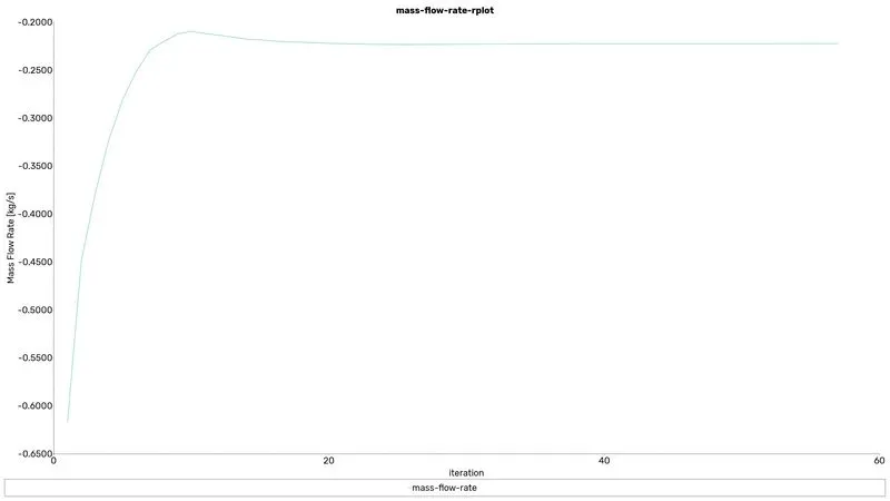
Mass flow rate
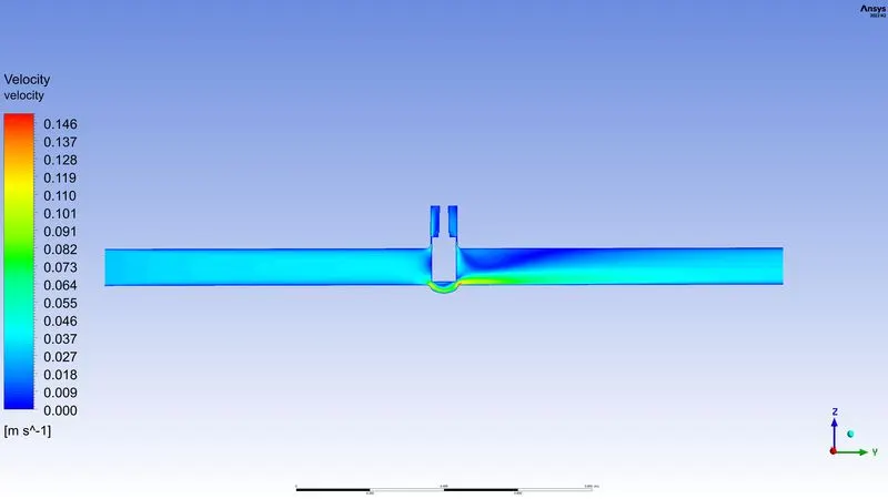
Velocity contour
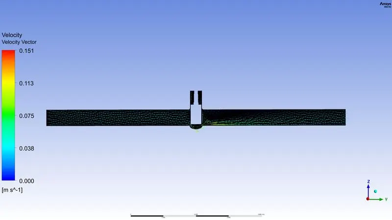
Velocity Vector
Pressure contour
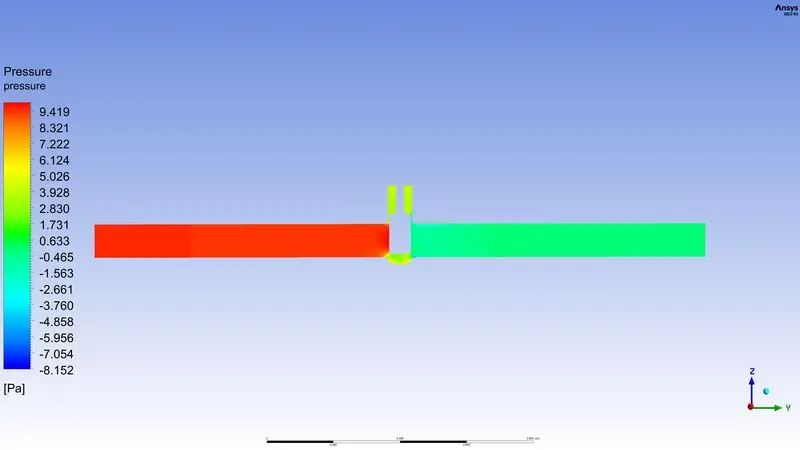
case 3:Valve opening=30%
Residuals
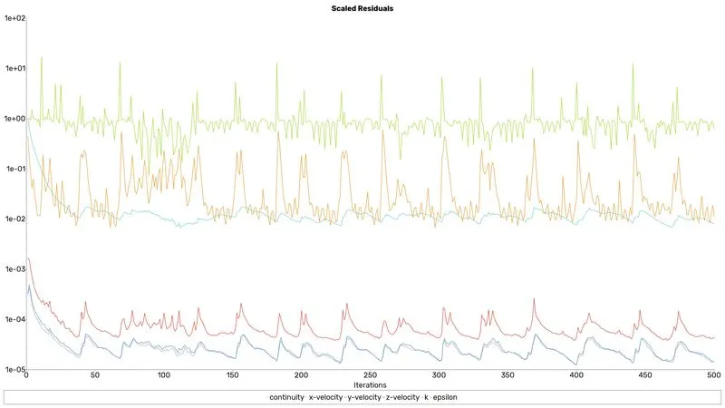
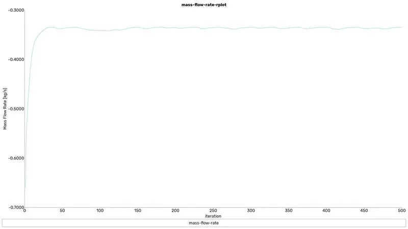
Mass flow rate
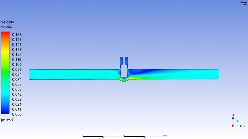
Velocity contour
Velocity Vector
Pressure contour
case 4:Valve opening=40%
Residuals
Mass flow rate
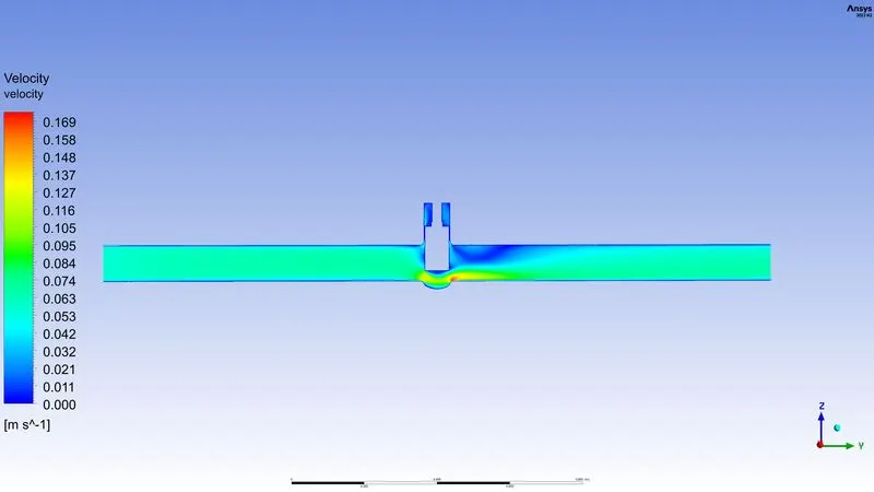
Velocity contour
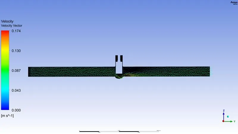
Velocity Vector
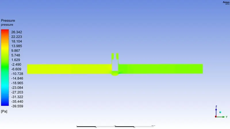
Pressure contour
case 5:Valve opening=50%
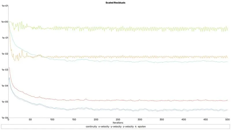
Residuals
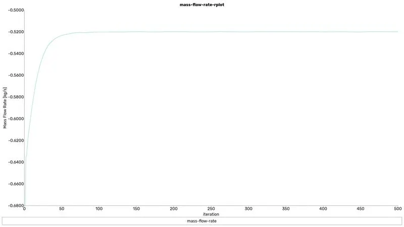
Mass flow rate
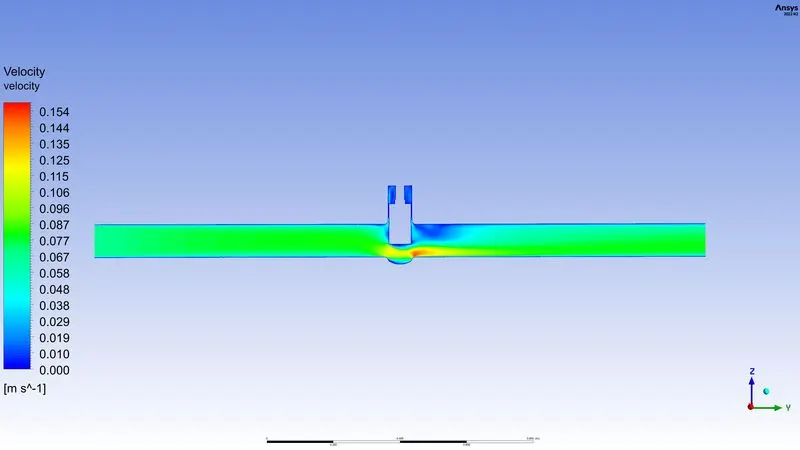
Velocity contour
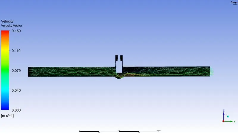
Velocity Vector
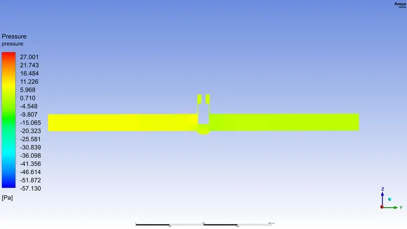
Pressure contour
case 6:Valve opening=60%
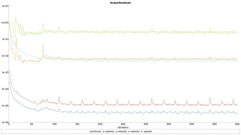
Residuals
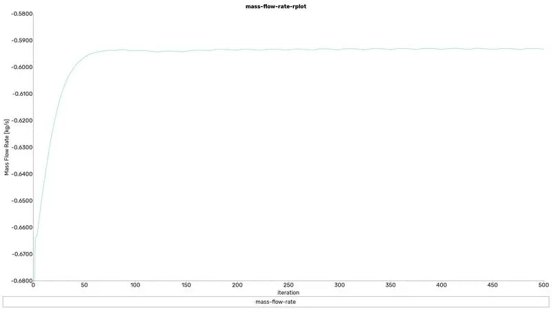
Mass flow rate
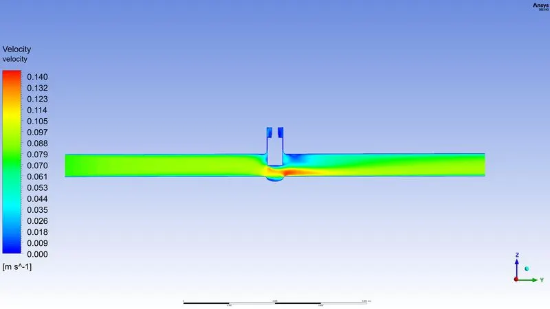
Velocity contour
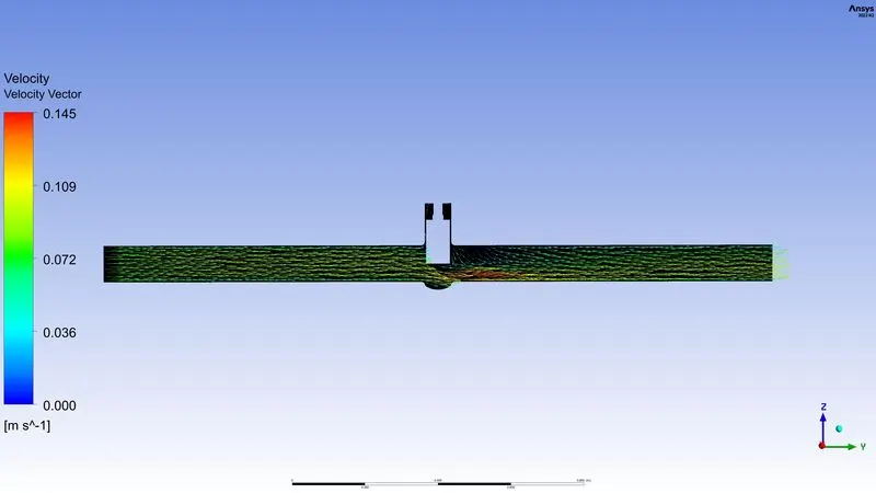
Velocity Vector
Pressure contour
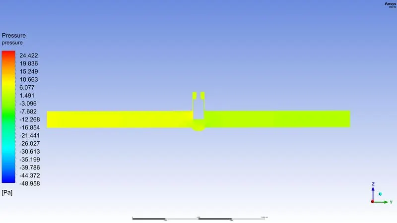
case 7:Valve opening=70%
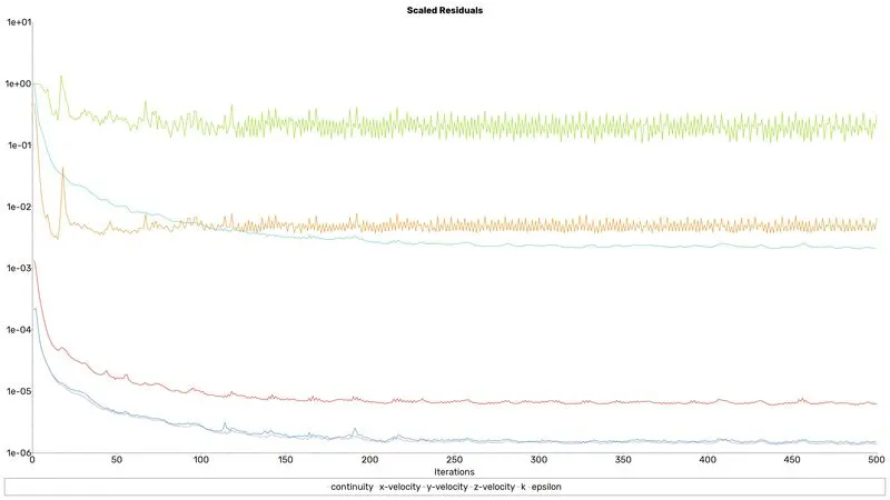
Residuals
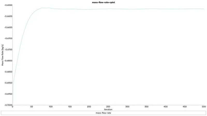
Mass flow rate
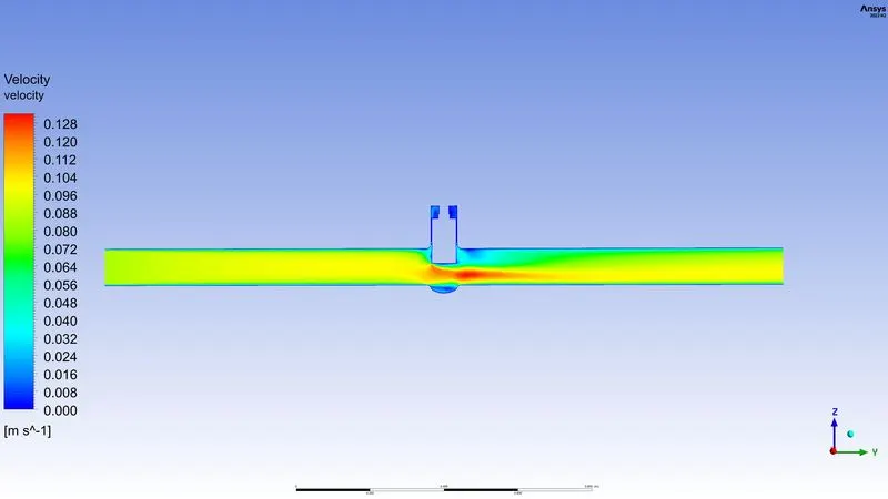
Velocity contour
Velocity Vector
Pressure contour
case 8:Valve opening=80%
Residuals
Mass flow rate
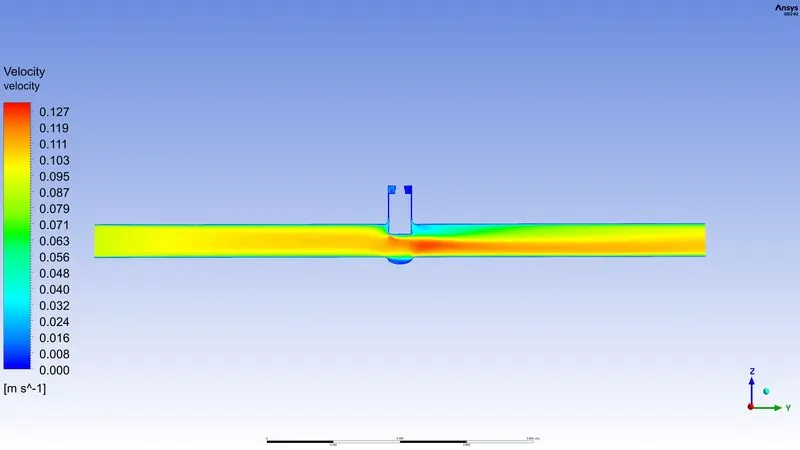
Velocity contour
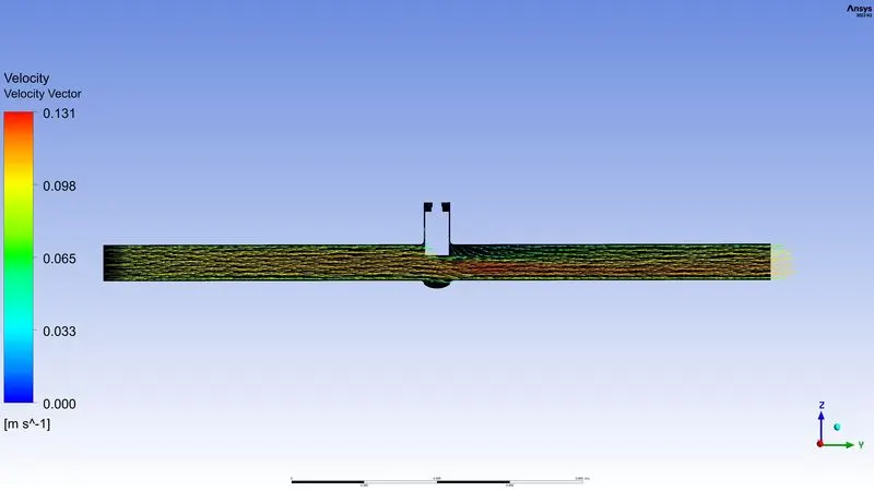
Velocity Vector
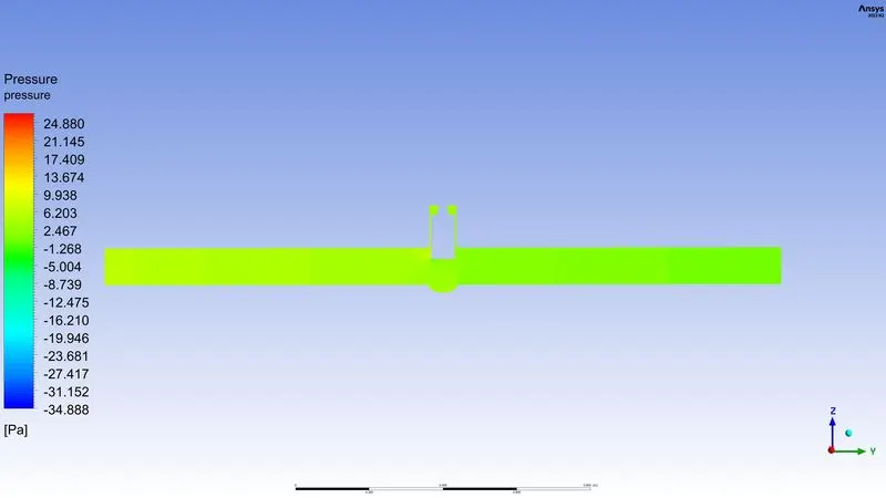
Pressure contour
Solution discussion
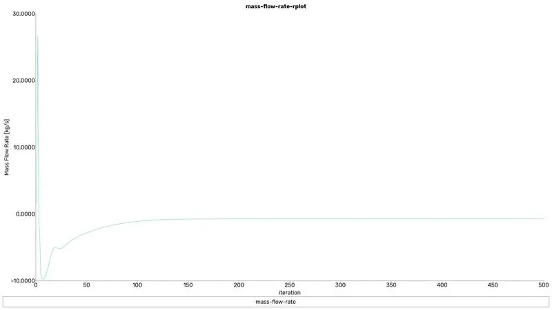
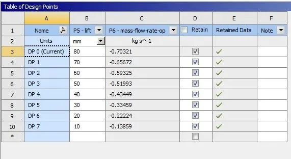
- The mass flow rate increases concerning the lift of the gate disc are increases.
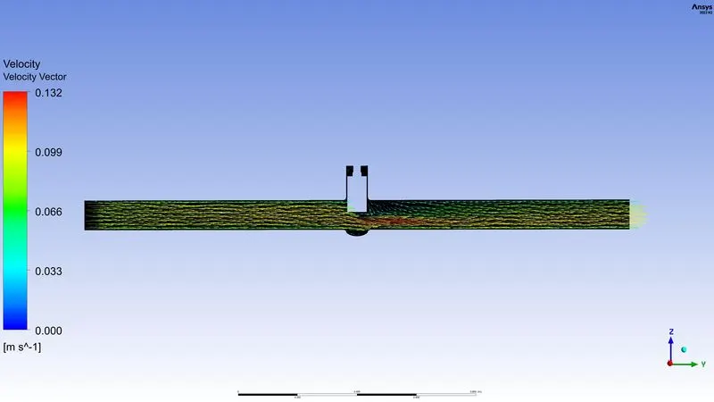
- The velocity of the flow will be maximum at the valve because the cross-sectional area of that region is small compared to another region's (Pipe region). After all, the valve gate covers the region.
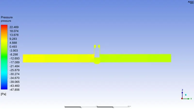
- From the initial valve opening the pressure from the side of entry because the valve just opens and by increasing the valve opening gradually the pressure is also commonly equal in all the regions.
- A parametric system reduces the work of setting up the solver.
- When we chose a gate valve for any case flow coefficient plays important role in the selection of valve and sizing of a valve, so calculating it is necessary
Flow Coefficient:
The flow coefficient of a device is a relative measure of its efficiency or the Valve Flow Coefficient (Cv) is a valve’s capacity for a liquid or gas to flow through it.
It is technically defined as “the volume of water at 60°F (in US gallons) that will flow through a valve per minute with a pressure drop of 1 psi across the valve.”
`C_v=Q sqrt ((SG)/(Delta p)`
cv=flow coefficient
Q=rate of flow
SG=specific gravity of the fluid
`Delta p`=pressure drop across the valve
Flow Factor
| Name | valve Distance | Mass flow rate[Kg/s] | The flow rate in gpm | Flow Co-efficient Cv | Flow factor kv |
| DP 7 | 10 | -0.13859405 | 2.196715693 | 57.68102258 | 49.89408453 |
| DP 6 | 20 | -0.22223787 | 3.52247024 | 92.49248144 | 80.00599645 |
| DP 5 | 30 | -0.33458795 | 5.303219008 | 139.2511085 | 120.4522089 |
| DP 4 | 40 | -0.43449097 | 6.886681875 | 180.8294328 | 156.4174594 |
| DP 3 | 50 | -0.51993258 | 8.240931393 | 216.3891082 | 187.1765786 |
| DP 2 | 60 | -0.59325102 | 9.403028667 | 246.9032796 | 213.5713369 |
| DP 1 | 70 | -0.65671962 | 10.40900598 | 273.318077 | 236.4201366 |
| DP 0 | 80 | -0.70321416 | 11.14594444 | 292.6684936 | 253.158247 |