Week 3 Challenge : CFD meshing on Turbocharger
Objective
Hear the mesh has to generate with the given model with a target length of Blade stage-1 = 1 mm,Blade stage-2 = 1 mm,Impeller = 2 mm,Shaft rotor = 1 mm,Turbo casing = 5 mm,Compressor casing = 5 mm and Inlet casing cover = 5 mm
The surface mesh has to be developed with the spot mesh with the surface mesh the tetra rapid volumetric mesh has been created
Mesh has been created by following the steps
step1:Initially, the model (turbocharger) is imported into ansa and checked for geometric clearance and cones present in the given model have been analysed and make a separate PID for the parts present in the model,
Picture of the model and the PID dialogue box
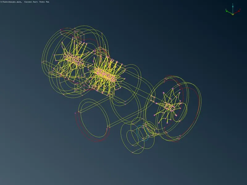
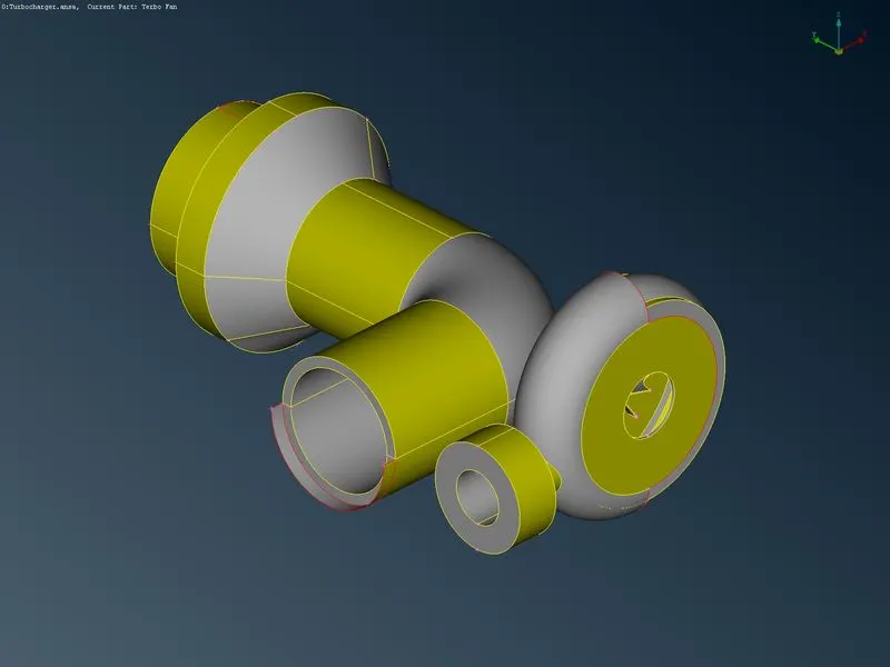
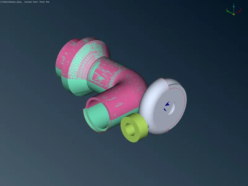
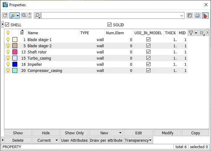
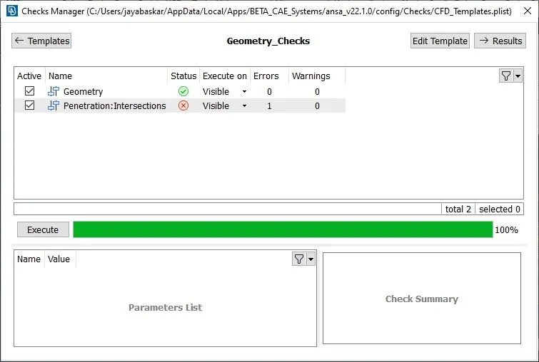
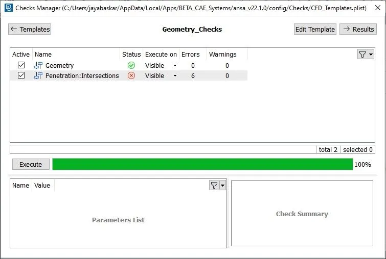
step2:From the imported file it will be apparent that the model has some red cones and intersection errors. To find the errors we can manually find or we can find them using checks→">→ checks manager→">→ geometric check in it we can evaluate the geometric part we need to evaluate
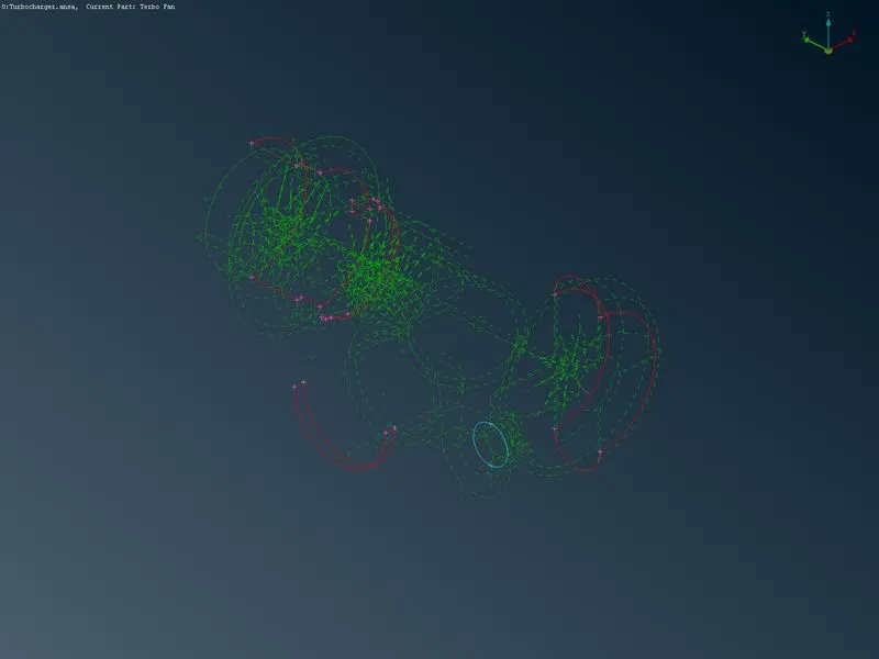
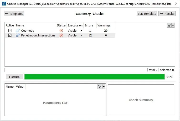
step3:After finding the present cons we need to clear those cons and the missing surface has to be created to make sure the created surface did not create any error in the model and solve the intersection error present in the model. Here we have already assigned the PID for the parts so we can clear the cones present in the parts separately and after we can check inter section error between the parts
the below pictures show the model before and after the topological cleanup
- compressor casing
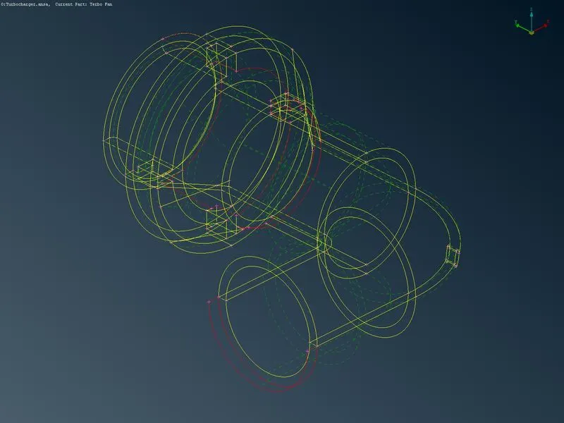
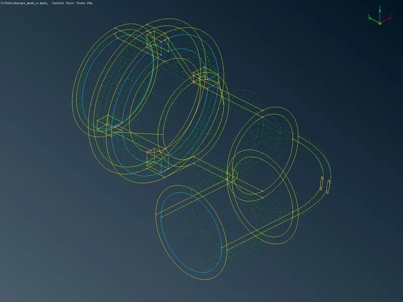
hear the topological error has been cleared and the open part of the part has been closed to create a volume mesh and there is a hole in the shaft region because of the shaft passing through the surface and some triple cones are present because of three surfaces meaning it will not affect the geometry - Turbo casing
as same as compressor casing hear also the topological and intersection errors have been cleared and closed the surface to create a volume mesh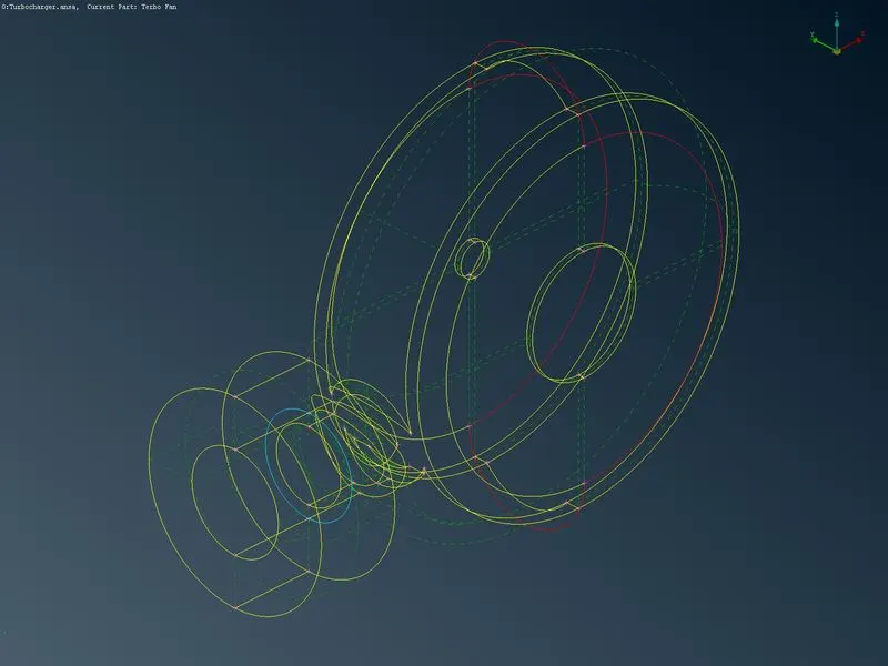
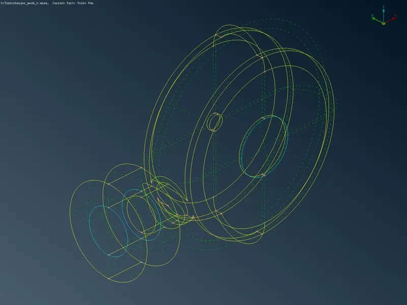
- Compressor blades
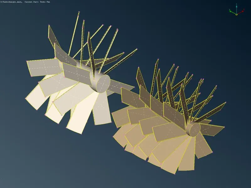
hear the model visually seems like there it does not have any error present in it so we run the geometric check to find error present in it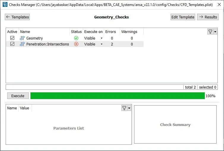
the geometric check shows that we have an intersection error in it so we need to check any over-lapping surface or any unwanted surface present in it after that we need to clear the errors to generate a mesh
the below pictures shows the blade after cleanup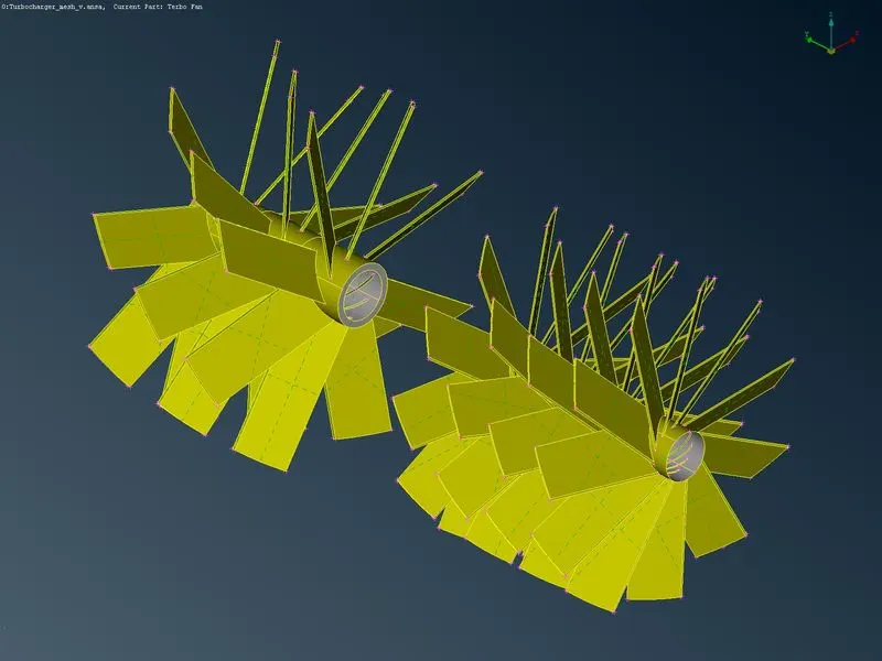
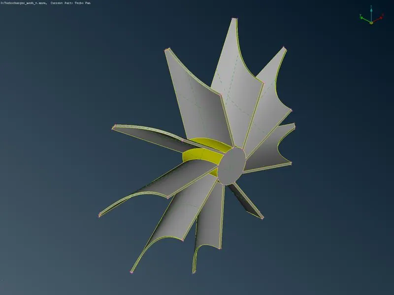
- Impeller
In the impeller, we need to follow the same procedure as the blades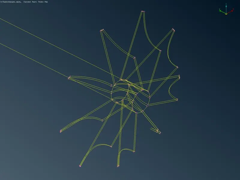
- Shaft
In the shaft, we need to solve the errors with the blades and impeller so that we can solve the intersection error present in it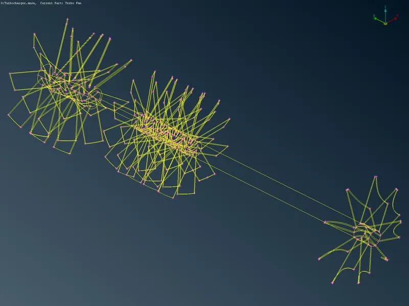
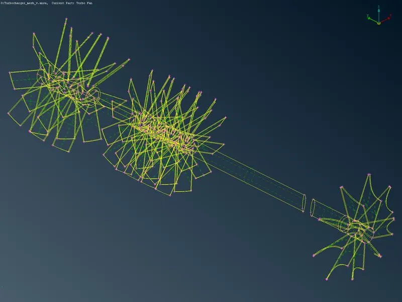
hear in the shaft parts it seems like some of the parts get deleted after cleanup because the shaft intersects in the casing so we deleted the internal surface crossing the casing and it will not creates any error because we create mesh for an internal flow analysis
Step 4:After all the geometric cleanup we can check it with the geometric check manager and the clean geometry has shown bellow
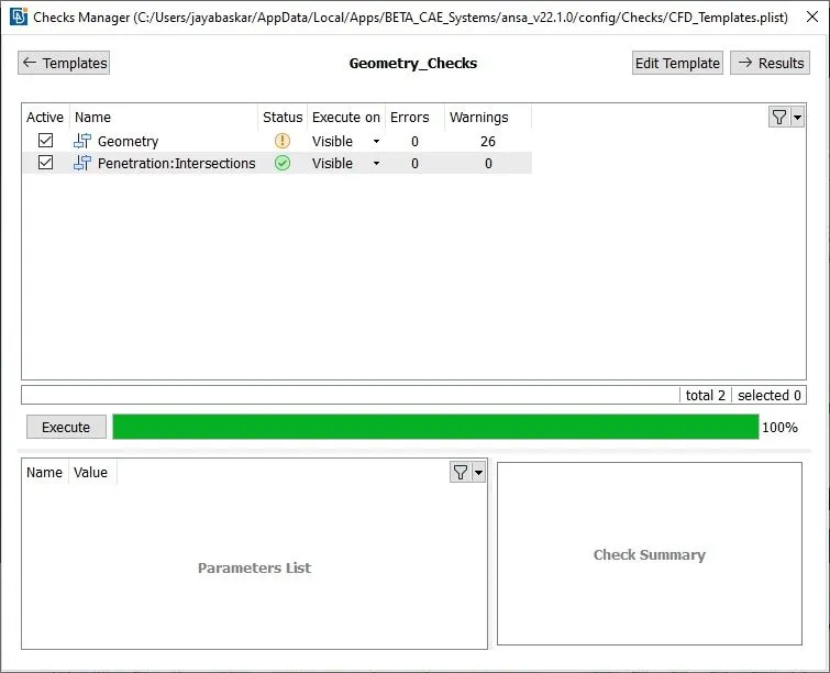
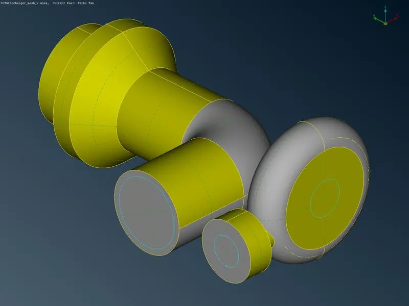
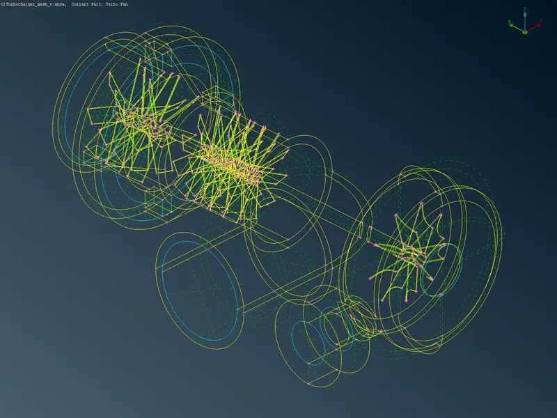
The warning shown in the geometric check is negligible and the triple cones in the geometry are required to create v mesh
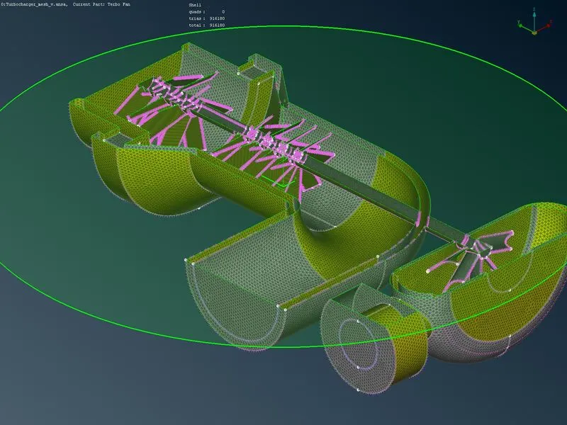
step 5:surface mesh
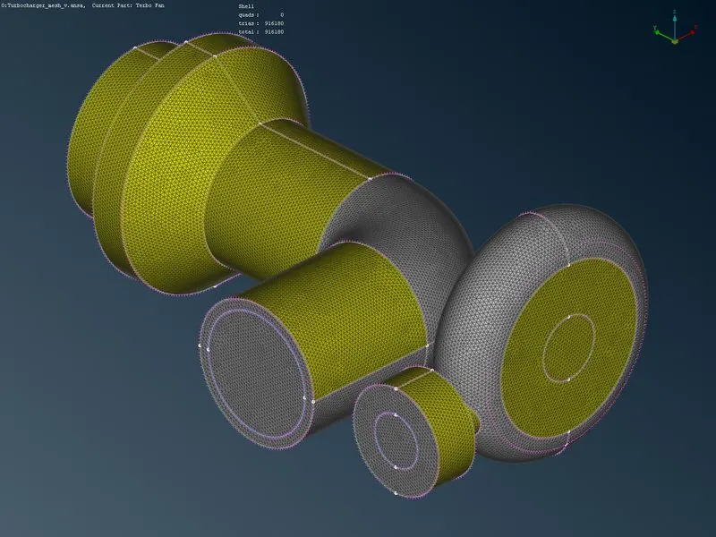
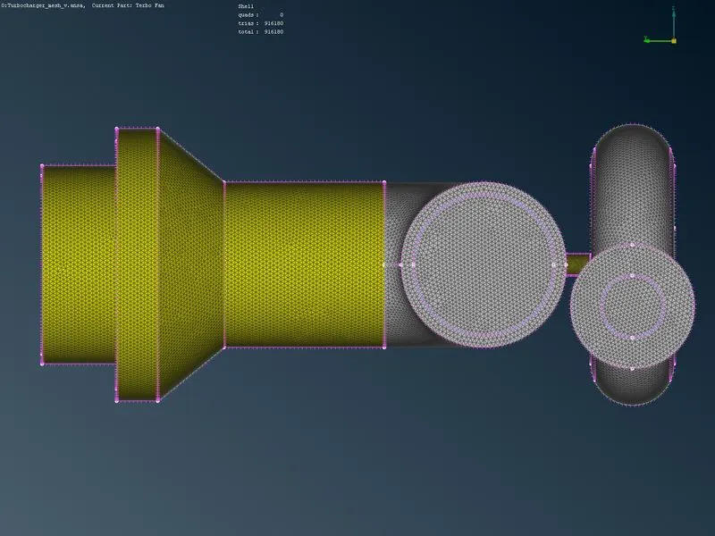
After completing the topological clearance the surface meshing has been obtained by specifying the perimeter length of the surface has been assigned and macros have been assigned concerning the required target length. Finally, the mesh parameters have been checked and generated a mesh with the spot mesh options in the mesh→">→ mesh generation
surface mesh output
step 5:volume mesh
In this volume mesh first, we have to define volume in the volume mesh. when we use the define volume option it auto-generated closed surface has the volume shown bellow
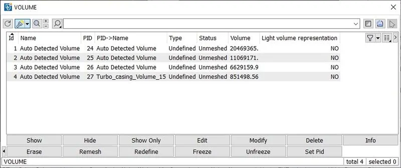
In my volume generation, it shows four volumes but we need only two volumes that are present in the internal flow region in the turbocharger compressor and turbo casing and the unwanted volumes are deleted in the step in this case 2 and 4 are unwanted volumes because it creates volume for the turbocharger material thickness after that we have to specify the type of mesh in the same dialogue box using the edit option
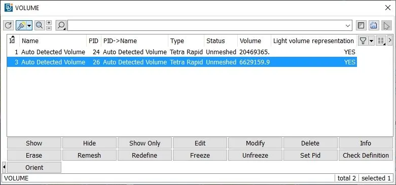
After completing those steps we have to generate volume mesh in two methods. in one method by simply using the mesh in the same dialogue box it will generate a new mesh for the specified volume or in another way we can go with volume mesh `->`unstructured mesh then choose the prefered mesh and select the component we want to generate a mesh and use middle click it will generate mesh
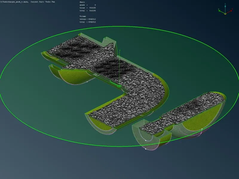
output
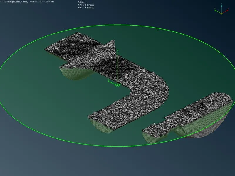
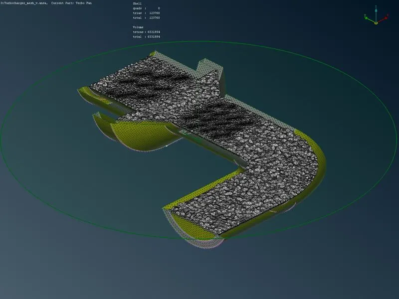
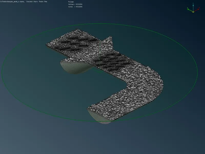
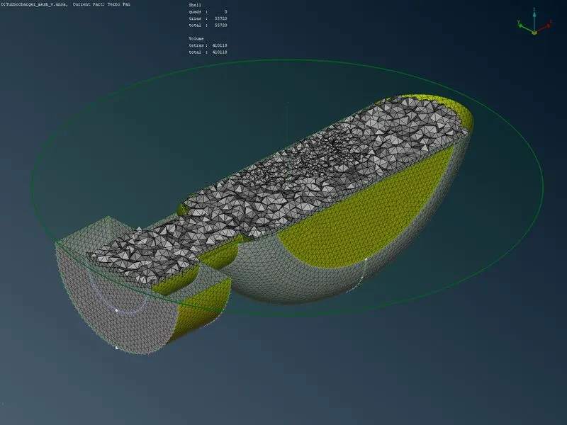
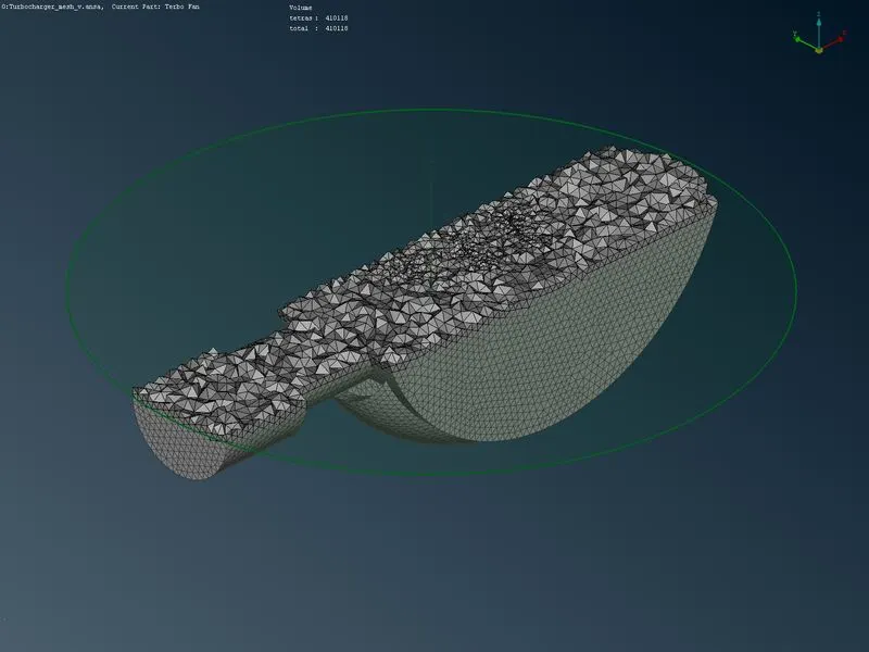
Unstructured Tetra Rapid volume mesh
conclusion
The volume mesh of the given turbocharger has been developed with tetra rapid and it contains a total of 916180 surface mesh elements and 6941268 volume mesh elements.
link for the uploaded google drive ansa file:https://drive.google.com/file/d/1ph2i6xBpyxaDCvS1ZhYbOgQjhn21muCV/view?usp=sharing