Week 4 Challenge : CFD Meshing for BMW car
Objective
Hear the mesh has to generate with the given model with a target length of
- Body - 3 mm
- Lights - 4 mm
- Grills - 1 mm
- Rims and Tyres - 2 mm
- Optical Rear view mirror - 2 mm
- Window - 2 mm
- Silencer - 3 mm
- Logo - 1 mm
After creating surface mesh for the entire car we need to build a tunnel to create a mesh for the external flow analysis but here we only make surface mesh for the tunnel because the volumetric mesh for the vast flow will take time to generate a mesh.
Mesh has been created by following the steps
step1:Initially, the model (BMW cars) was imported into ansa and it seems like the model is not properly so the model changed into the respective axis
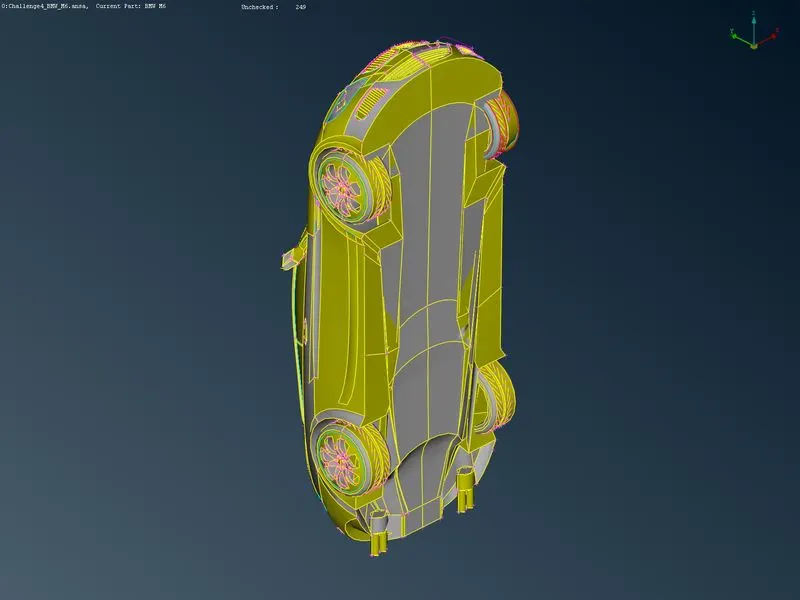
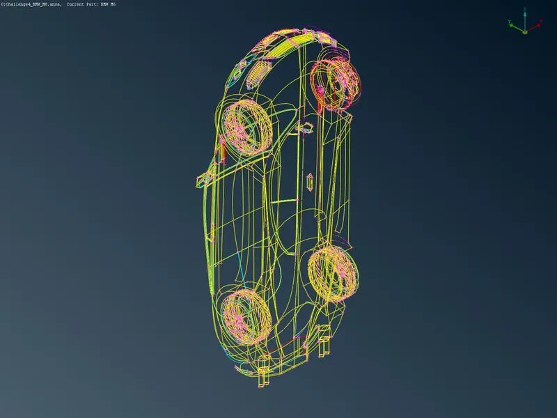
The above shown are isometric views of the car but the viewing angle will be in between the bottom and the side face
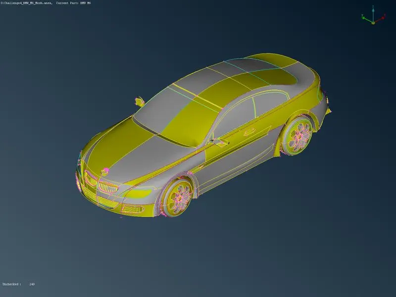
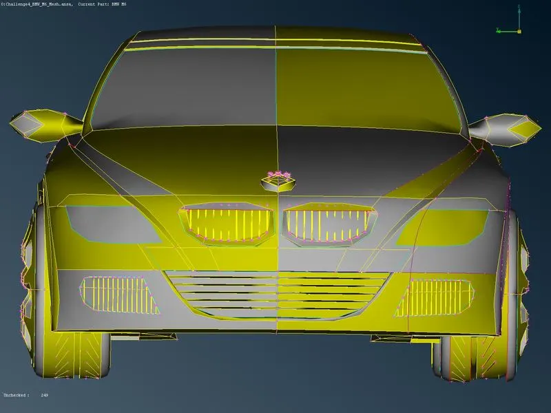
The above images are the isometric front and top view of the model after it was properly placed
step2:The model of the car is asymmetric so we can remove half of the car and do a mesh and then we copy to mirror the model
note: The logo of the car is not asymmetric so we don't remove the half part
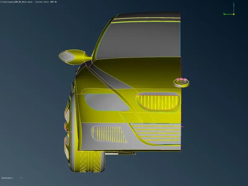
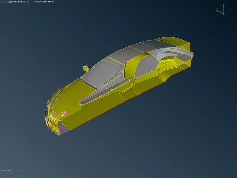
step3: After completing this step check for geometric errors and cones present in the given model has been analysed in the model for that we use check->`check manager`->` geometric check hear we can find all the errors and intersection in the model
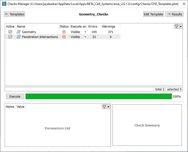
The model is very big so we split it and do it one by one instead of doing with all so I used to store different locks for the front parts
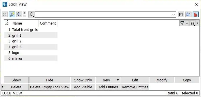
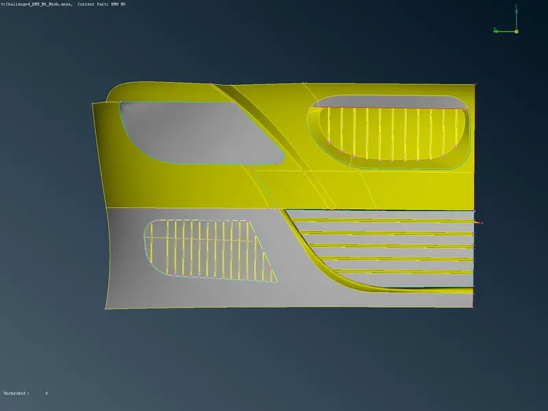
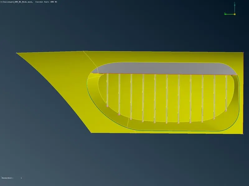
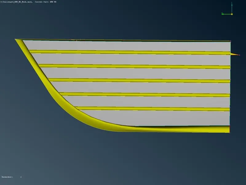
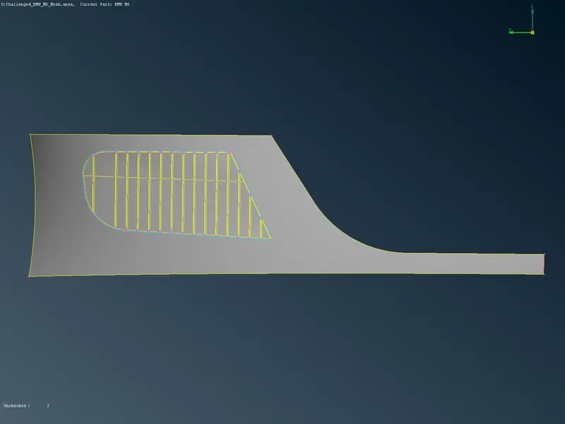
hear we can access the parts easily and then clear the errors separately from the huge model and starts the cleanup from the model and cleared all the geometric errors and intersection error present on it and shown bellow
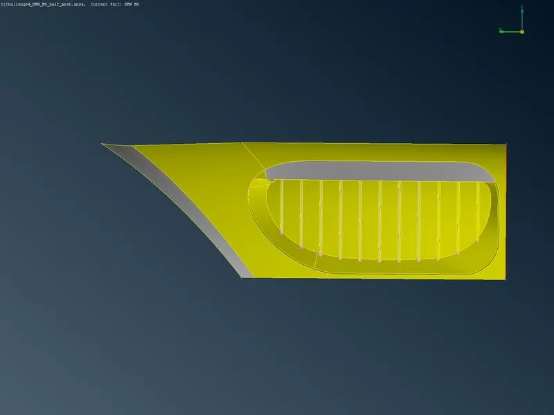
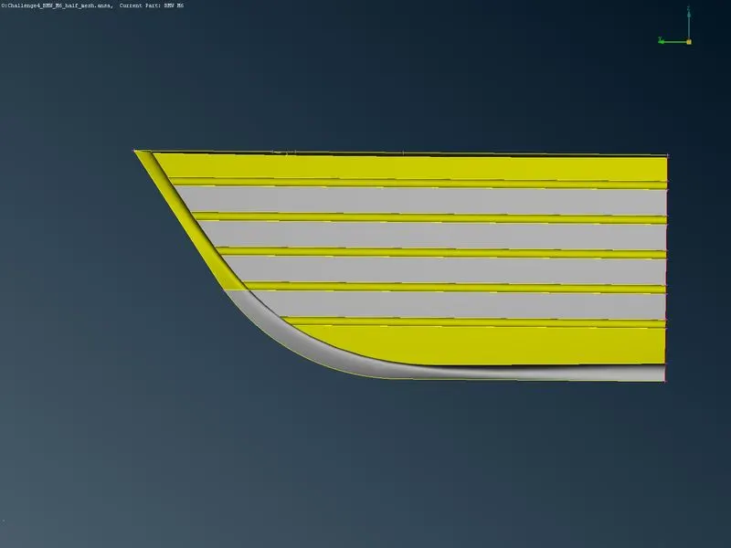
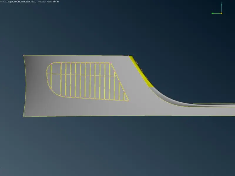
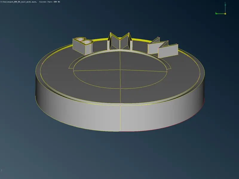
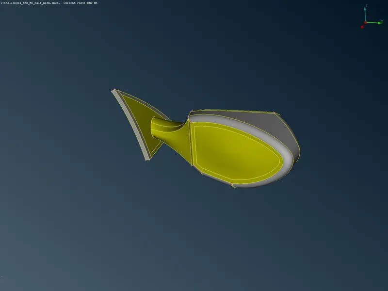
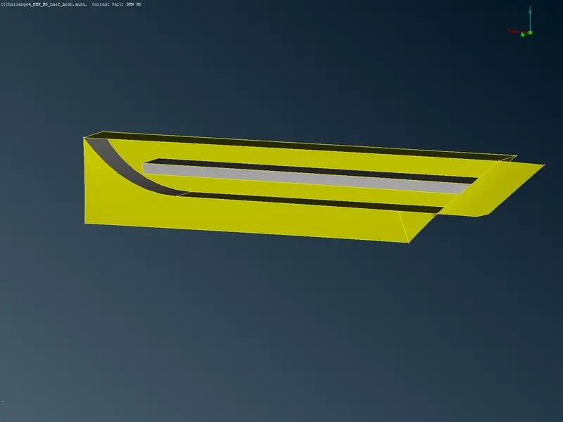
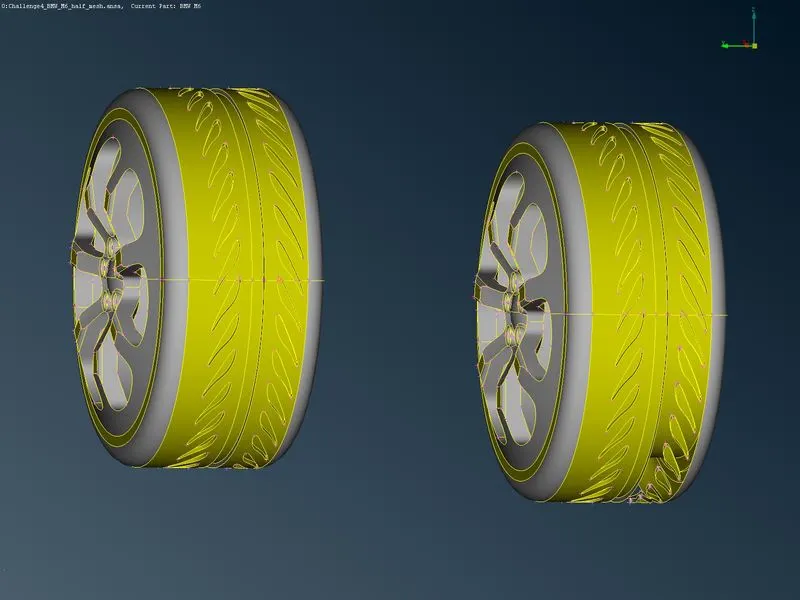
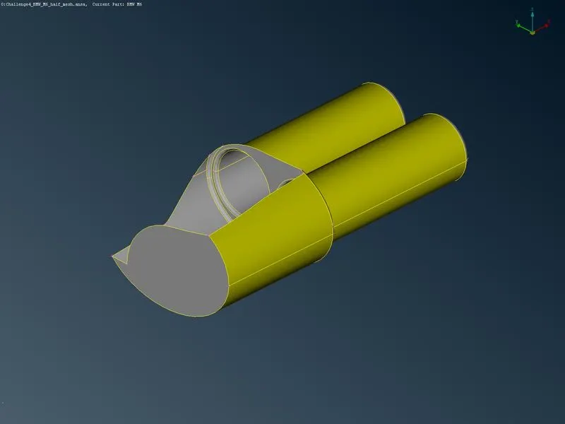
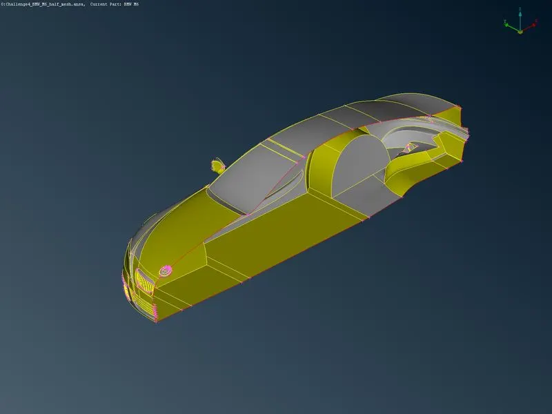
The above images are clean geometry and ready or the mesh to double check we can use geometric chech
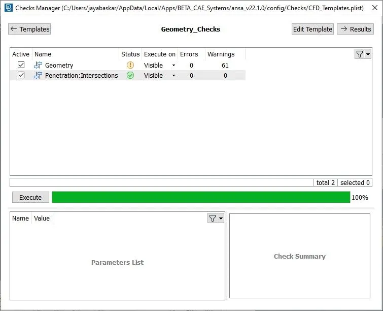
The showing warnings are ignorable because they all are single cones present on the asymmetric side to create the mirror and others are mixed, convex and concave cones
step4:surface mesh
After completing the topological clearance the PID or the parts are assigned and the surface meshing has been obtained by specifying the perimeter length of the surface has been assigned and macros have been assigned concerning the max target length and minimum target length and defined the quality criteria for the mesh has been defined. Finally, the mesh parameters have been checked and generated a mesh with the CFD mesh options in the mesh→ mesh generation
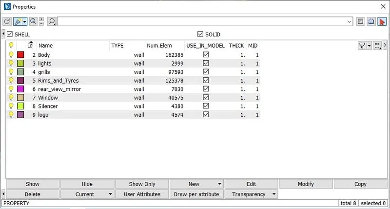
The above image shows the assigned PID concerning the given names for the easy access
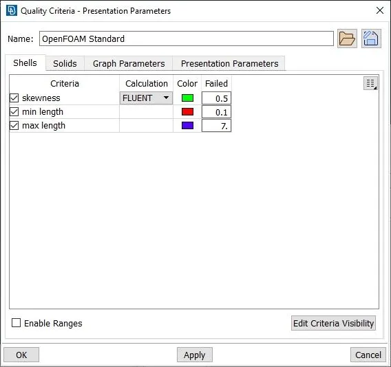
After assigning the mesh parameters and mesh target length we mesh it separately by pat by part and hit an all it
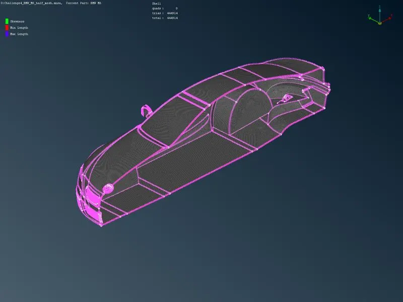
The above mesh is the complete mesh of the one half of the body
step5:Mirroring half part
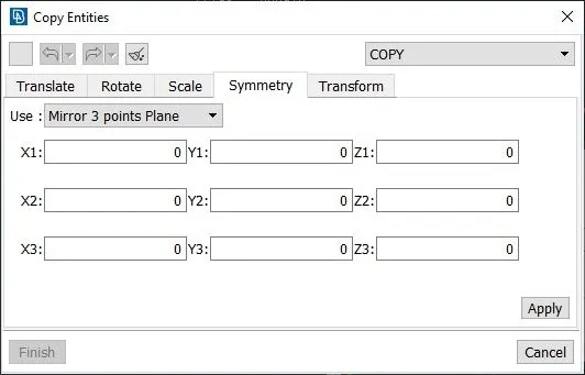
After completing the surface mesh of the half part of the car we mirror the half part with the 3-point symmetric way. to do that go to the transfer`->` copy and select all the entities without logo because the logo we maintain full part as it is and with the opened dialogue box go to the symmetric `->`three-point method after that select 3 point that places properly in the model and use apply for preview and finish for mirror the image
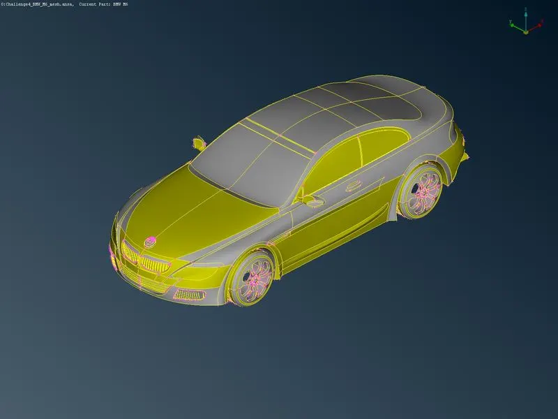
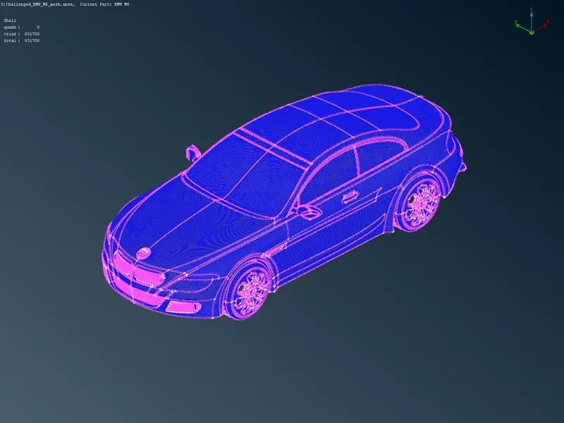
check whether it has any missing parts and check the mesh if it raises any off elements. after the mesh freeze the entire model it will maintain the model as it is when you freeze
step5:Tunnel creation
The tunnel has to be created with the standard to maintain proper flow analysis after meshing
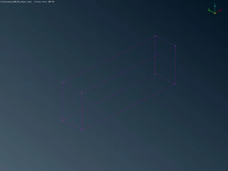
x will be the total length of the car we get 1306 approximately applied 1310 hear and bellow ate the conditions to create the tunnel
- the tunnel from the front face must be 4x distance
- the tunnel from the back face must be 6x distance
- the tunnel from the side face must be x distance(Both sides)
- the tunnel from the top face must be 4x distance
- the bottom face has not been considered, because the flow analysis majorly concentrates on the top surfaces so we can create the bottom face at the distance that we chose
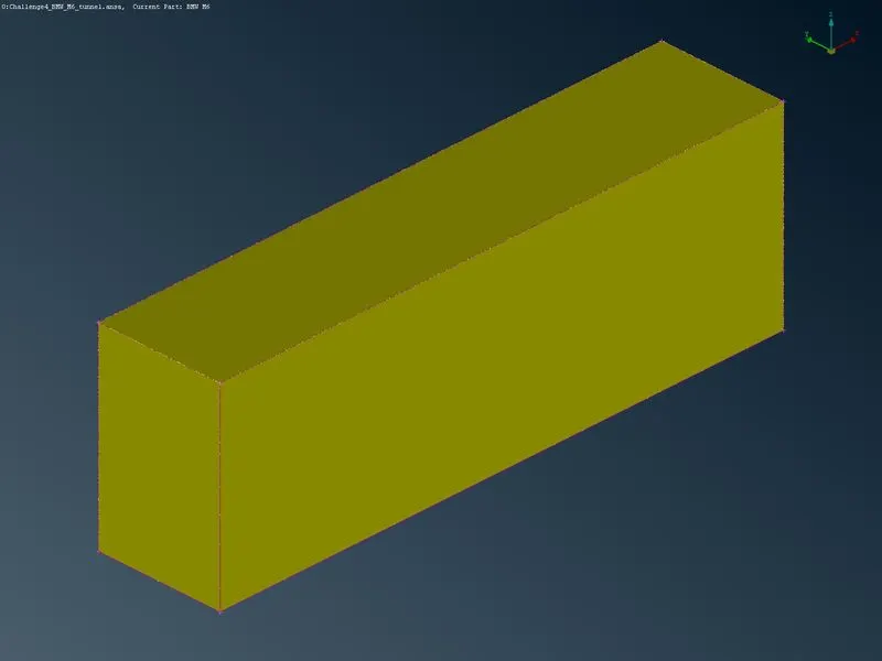
with these conditions, the tunnel has been created by creating points (topo`->` points`->`relative) it will greater a point relative to a selected point so we can create it from the hot points presented on the surface. with this hot point, we can able to create curves the curves have been used to create wind tunnel surface
step6:Tunnel mesh
After completing the tunnel building we start mesh by applying the tunnel spacing heat we use two ways of spacing the first one is auto CFD which is used for the top and bottom space another method is manual spacing applied for all the side surfaces of the tunnel
hear I used 100 for the bottom and 200 for the top surface because the meshing of the wind tunnel will require a dedicated processing system so I used maximum value for creating the mesh
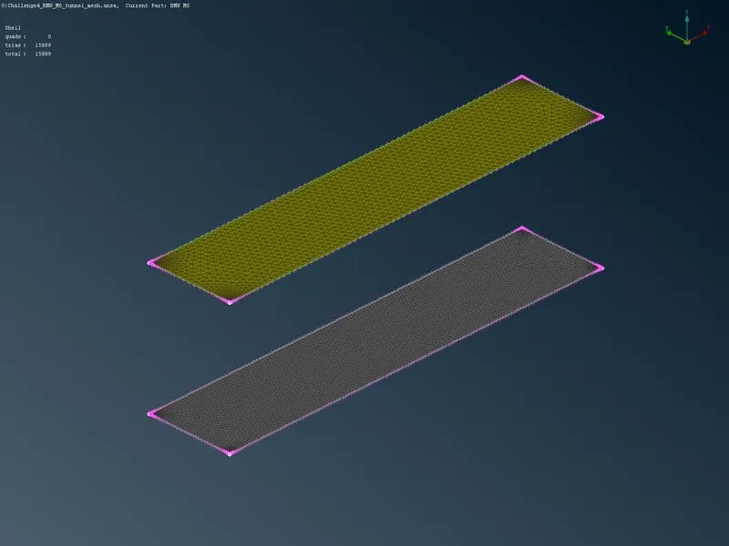
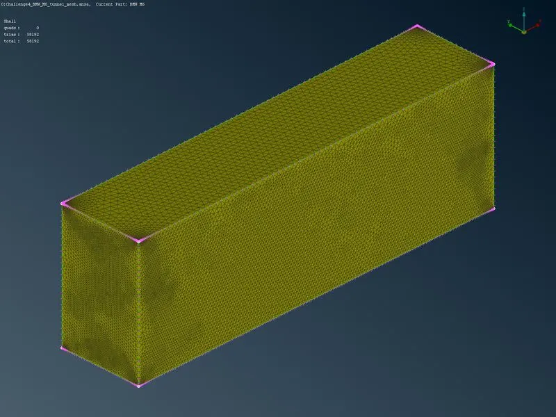
The tunnel mesh has been shown above for a more clear view of the model I use cut so it shows the internal parts
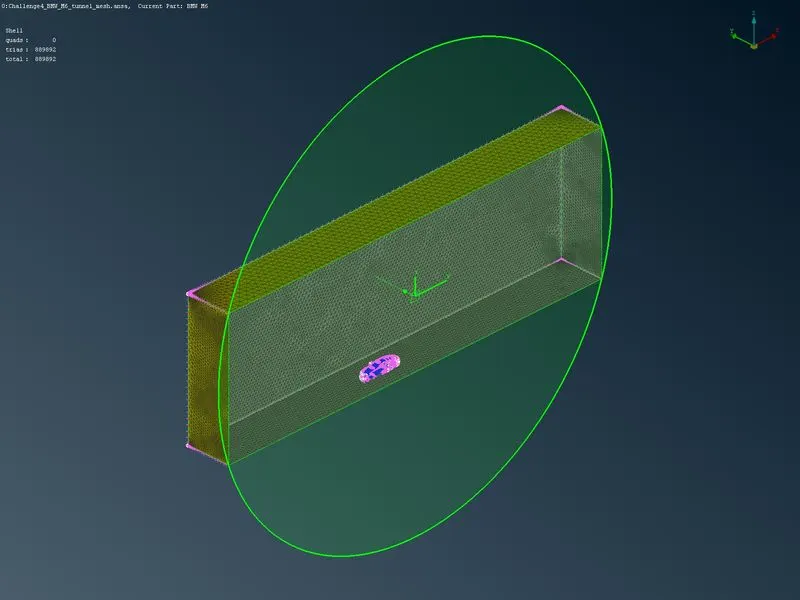
Meshing Wind tunnel volume with tetra elements may take a long time so the surface mesh has been submitted
conclusion
The surface mesh of the given model and wind tunnel has been developed with tetra elements and it contains a total of 889892 surface mesh elements present in the obtained mesh.
link for the uploaded google drive ansa
file:https://drive.google.com/file/d/1ivg5buiNrP89tA7NhJ3Qz1RknnVvHK3o/view?usp=sharing