Week 9 - Parametric study on Gate valve.
Aim: To perform a parametric study on the gate valve simulation by setting the opening from 10 % to 80%.
Objectives:
- Obtain the mass flow rates at the outlet for each design point.
- Calculate the flow coefficient and flow factor for each opening and plot the graph.
- Discuss the results of the mass flow rate and flow coefficient.
INTRODUCTION :
In this challenge, we are rying to study how the mass flow rate is going to change for different lifts of the gaye disc, so the only change in the case setup will be lift of the gate valve. By parameterizing the lift value, we are essentially automating the mesh, setup, solution and post processing stages which saves time and also more effective.
Gate valve :
- Gate valves are used to shut off the flow of liquids rather than for flow regulation. When fully open, the typical gate valve has no obstruction in the flow path, resulting in very low flow resistance.The size of the open flow path generally varies in a nonlinear manner as the gate is moved. This means that the flow rate does not change evenly with stem travel. Depending on the construction, a partially open gate can vibrate from the fluid flow.
- Gate valves are mostly used with larger pipe diameters (from 2" to the largest pipelines) since they are less complex to construct than other types of valves in large sizes.
- At high pressures, friction can become a problem. As the gate is pushed against its guiding rail by the pressure of the medium, it becomes harder to operate the valve. Large gate valves are sometimes fitted with a bypass controlled by a smaller valve to be able to reduce the pressure before operating the gate valve itself.
- They can be found in petrochemical industries, power plans and widely in the pipeline industries.
Flow factor :
The kV-factor for a given valve is a constant which in a simple way states the valve capacity. The kV-factor is determined by the valve manufacturer by experiments. The kV factor specifies the water flow in m3 through the valve in one hour at a pressure drop across the valve of 1Bar
The metric equivalent flow factor (Kv) is calculated using metric units.

where,
- Kv is the flow factor (expressed in m3·h−1).
- Q is the flowrate (expressed in cubic metres per hour m3·h−1),
- SG is the specific gravity of the fluid (for water = 1),
- ∆P is the differential pressure across the device (expressed in bar).
Kv can be calculated from Cv using the equation,

The kv factor or value as it is also called is defined in VDI/VDE Richtlinien No. 2173. A simplified version of the definition is: The kv factor of a valve indicates "The water flow in m3/h, at a pressure drop across the valve of 1 kgf/cm2 when the valve is completely open.
Flow coefficient :
The flow coefficient of a device is a relative measure of its efficiency at allowing fluid flow. It describes the relationship between the pressure drop across an orifice valve or other assembly and the corresponding flow rate.
Mathematically the flow coefficient Cv (or flow-capacity rating of valve) can be expressed as :

where:
- Q is the rate of flow (expressed in US gallons per minute),
- SG is the specific gravity of the fluid (for water = 1),
- ΔP is the pressure drop across the valve (expressed in psi)
Procedure:
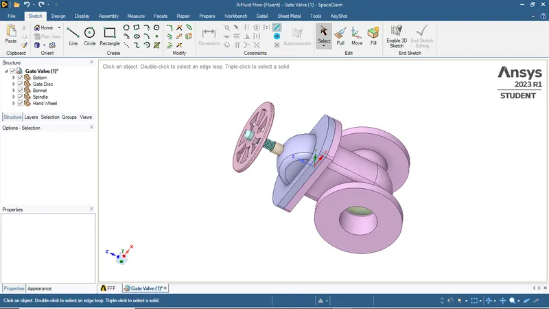
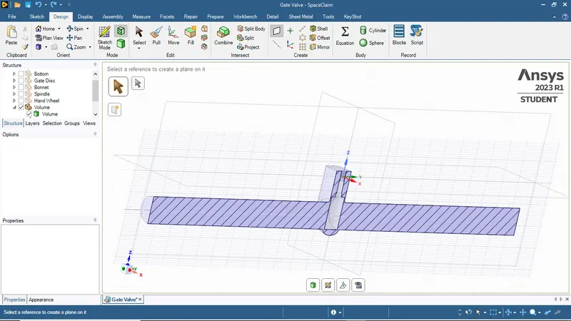
- Import the given gate valve model into spaceclaim and use the pull tool to extend either sides of the valve pipe to 800mm.
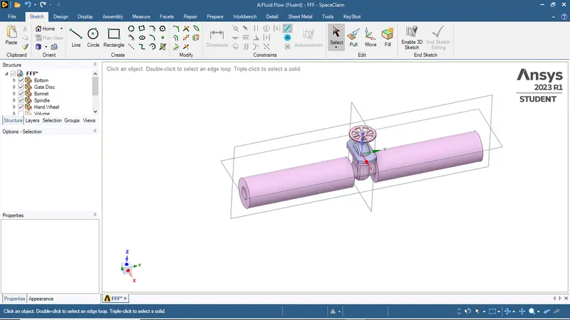
- To provide gate valve lift, isolate the gate disc and spindle, and move those components to 10mm in positive z-direction using move tool under design tab. Now, click the Create parameter option under Groups tab to create it as the input parameter for the simulation.
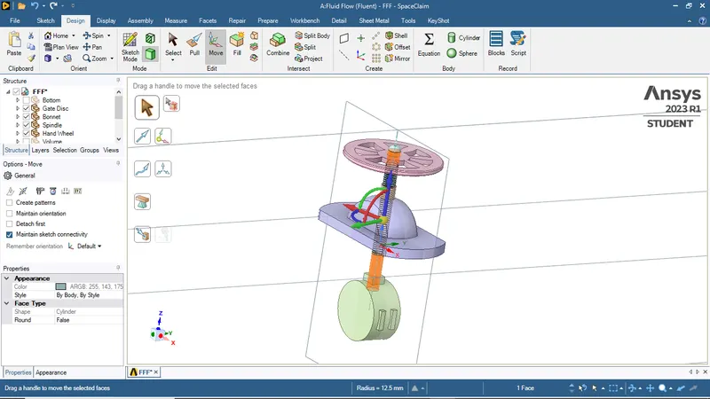
Hide the bonnet and hand wheel, and use Volume Extract option under Prepare tab to extract the fluid volume by selecting the edges of the fluid domain in the gate valve model.
- Make sure that the fluid volume is extracted properly and also the lift of the gate valve is set to 10mm.
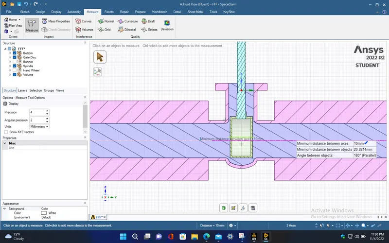
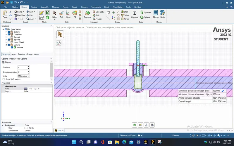
- The inner diameter of the valve pipe in which the fluid is flowing, is measured to be 100mm. So, for 10% to 80% of the gate valve opening, the lift of the gate valve which is given as the input parameter, is to be taken from 10mm to 80mm with 10mm increment. Now, close the spaceclaim.
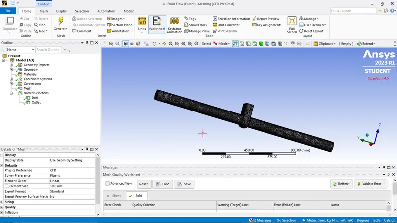
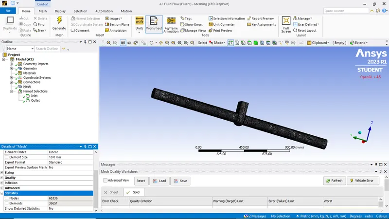
Open the mesh window and give the required named selections for model. Now, generate the mesh by choosing the mesh element size as 10mm and the maximum mesh size also to be 10mm which generates a uniform mesh.
SETUP AND SOLVING :
- Setup the simulation by providing the following input parameters in the setup window.
|
Model |
Settings |
|
Space |
3D |
|
Time |
Steady |
|
Viscous |
RNG k-epsilon turbulence model |
|
Wall Treatment |
Standard Wall Functions |
|
RNG Swirl Dominated Flow Option |
Enabled |
Material properties :
|
Fluid |
water-liquid |
|
Density |
998.2 kg/m^3 |
|
Cp (Specific Heat) |
4182 J/(kg K) |
|
Thermal Conductivity |
0.6 W/(m K) |
|
Viscosity |
0.001003 kg/(m s) |
|
Molecular Weight |
18.0152 kg/kmol |
Boundary conditions :
|
inlet |
|
|
Reference Frame |
Absolute |
|
Gauge Total Pressure [Pa] |
10 |
|
Supersonic/Initial Gauge Pressure [Pa] |
0 |
|
Direction Specification Method |
Normal to Boundary |
|
outlet |
|
Backflow Reference Frame |
Absolute |
|
Gauge Pressure [Pa] |
0 |
|
Backflow Direction Specification Method |
Normal to Boundary |
|
wall-volume_volume |
|
|
Wall Motion |
Stationary Wall |
|
Shear Boundary Condition |
No Slip |
Solution method :
|
Pressure-Velocity Coupling |
Coupled |
- Here, we enable the gravity having value of 9.81 m/s^2 in negative z-direction since the gravity acts perpendicular to the direction of flow in this setup.
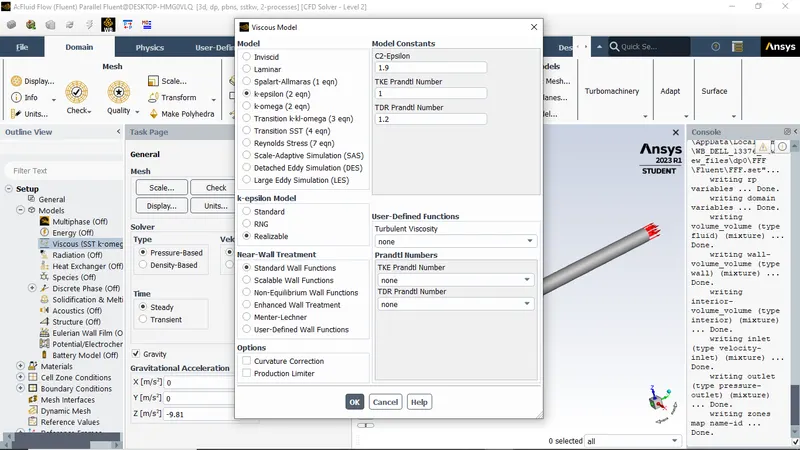
- For this setup, we choose k-epsilon RNG turbulence model with swirl dominated flow option enabled since this visous model will be the better option for incompressible flows having swirling effects
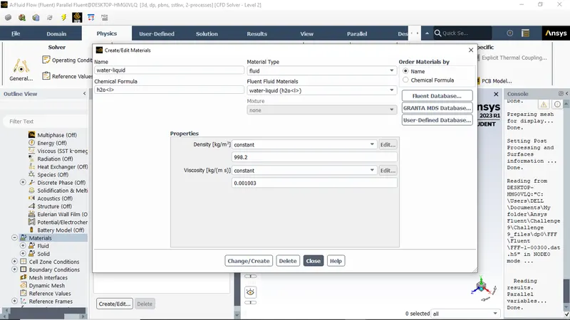
- Select the fluid material as water from fluent database.
- Make sure the fluid material for the fluid domain cell zone is set to water.
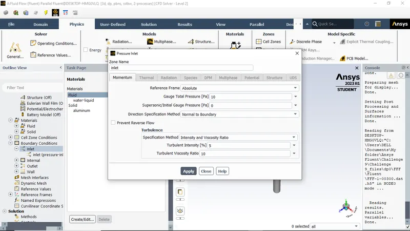
- Set the boundary condition type for inlet as pressure inlet with total gauge pressure of 10 Pa.
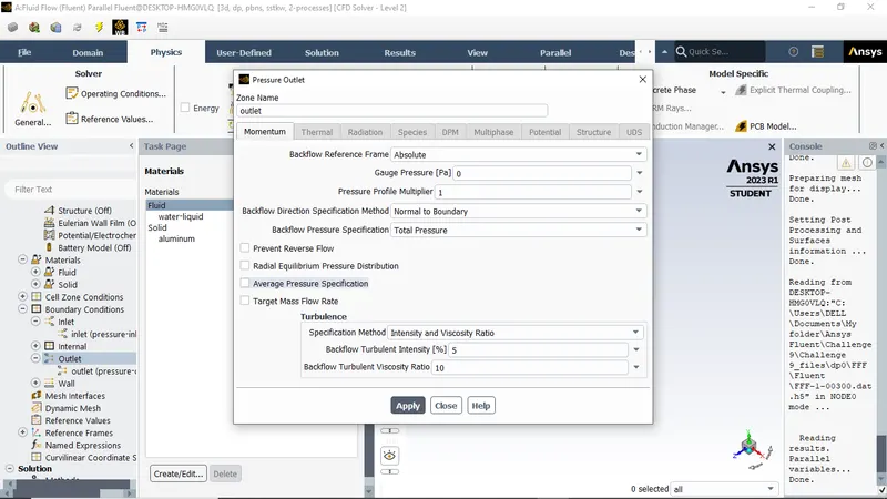
- For outlet, select the type as pressure outlet with gauge pressure of 0 Pa (open to atmosphere).
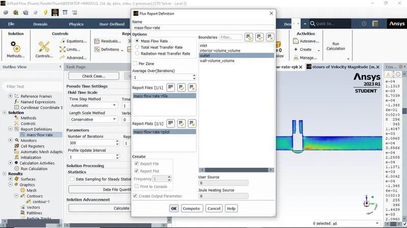
- Create the report definition for mass flow rate at outlet and enable the create parameter option to set it as the output parameter for the simulation.
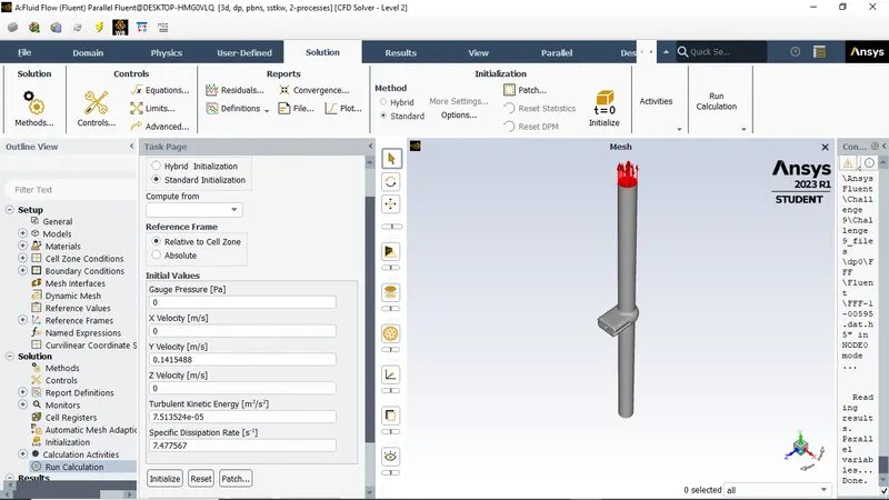
Initialize the simulation using Standard simulation.
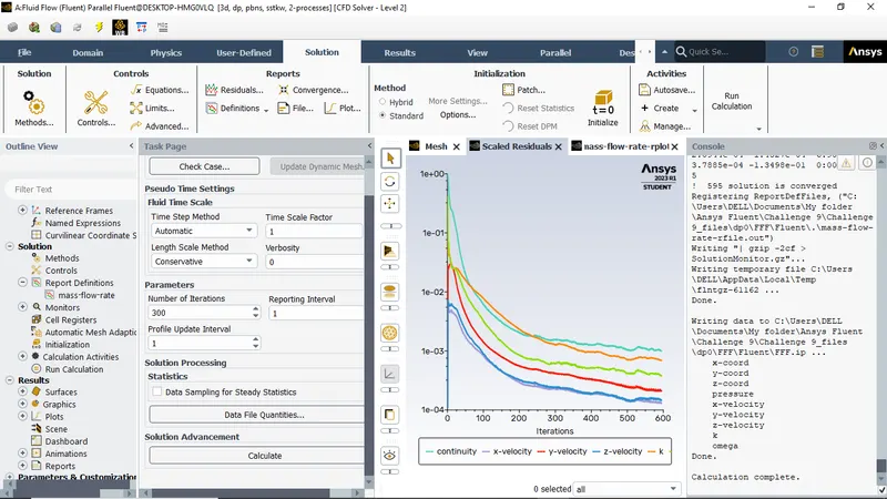
Run for 300 iterations
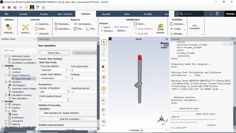
Results are shown below
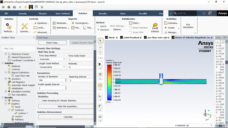
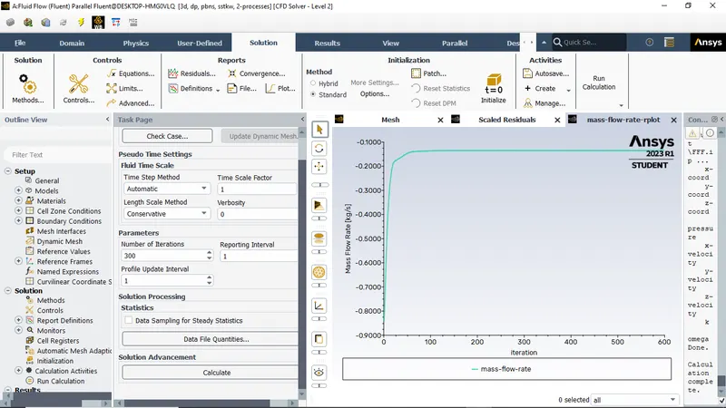
By using the paramteric option we can create design point in the simulation and calculate the mass flow rate at various heights of valve openings.
Parameter set window :
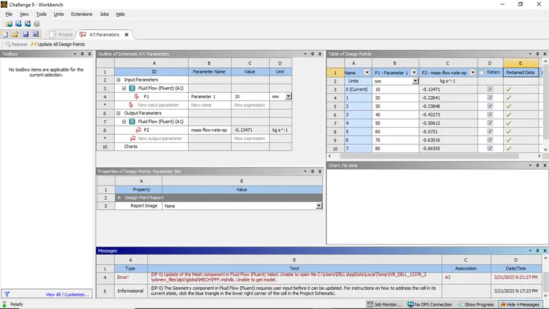
| GATE VALVE POSITION (in 'mm') | NUMBER OF MESH ELEMENTS | MASS FLOW RATE AT OUTLET (in 'kg/s') | GAUGE PRESSURE DIFFERENCE ACROSS THE VALVE (in 'bar') | Volumetric flow rate | FLOW FACTOR (KV) | FLOW COEFFICIENT (CV) | ||
| (in 'm^3/s') | (in 'm^3/hr') | |||||||
| CASE - 1 | 10 | 65336 | 0.13499455 | 0.0001 | 0.000135401 | 0.487442708 | 42.16379425 | 48.74427081 |
| CASE - 2 | 20 | 65336 | 0.22641011 | 0.0001 | 0.000227091 | 0.817528983 | 70.71625703 | 81.75289829 |
| CASE - 3 | 30 | 65336 | 0.3384763 | 0.0001 | 0.000339495 | 1.222181224 | 105.7186758 | 122.2181224 |
| CASE - 4 | 40 | 65336 | 0.43273231 | 0.0001 | 0.000434034 | 1.562523888 | 135.1583163 | 156.2523888 |
| CASE - 5 | 50 | 65336 | 0.50612114 | 0.0001 | 0.000507644 | 1.82751866 | 158.0803641 | 182.751866 |
| CASE - 6 | 60 | 65336 | 0.57209576 | 0.0001 | 0.000573817 | 2.065741962 | 178.6866797 | 206.5741962 |
| CASE - 7 | 70 | 65336 | 0.63015744 | 0.0001 | 0.000632054 | 2.275392963 | 196.8214913 | 227.5392963 |
| CASE - 8 | 80 | 65336 | 0.66555456 | 0.0001 | 0.000667557 | 2.403206034 | 207.8773219 | 240.3206034 |
Conclusions:
- From the above plots, we can see that, as we increase the gate valve height, the mass flow rate at outlet increases since the gate valve allows more fluids to flow when the gate valve is maximum.
- Also we can see that, the flow coefficient increases as the gate valve position is increased which allows more fluids to flow through the valve.