Week 3 Challenge : CFD meshing on Turbocharger
Aim: To generate volumetric mesh for a given Turbo charger model.
Objective: To generate volumetric mesh for a given Turbo charger model by performing topo clean up, surface mesh and defining volumes.
Procedure: Import the given model using file import option.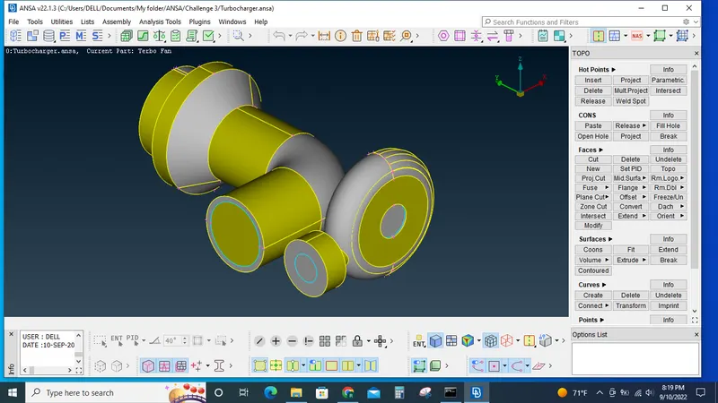
By toglling between the availble PID's and the not and or options in the view tab identify the overlaped surfaces.
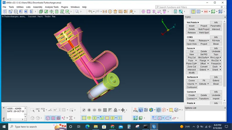
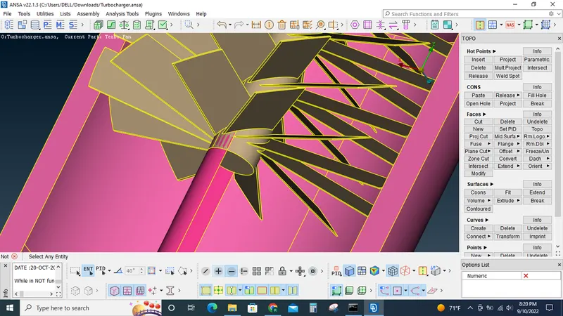
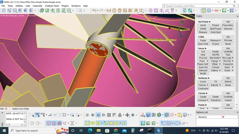
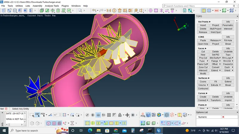
Once the overlapping surfaces arer identified delete those surfaces using the universal delete option.
In the shaft, blade set and impeller model delete the overlapping and unwanted surfaces are deleted such that we can look through the shaft from one end to the other end by temporarily hiding the top most and bottom most surfaces of the shaft set. This is done to create these component in manner it becomes a single volume.
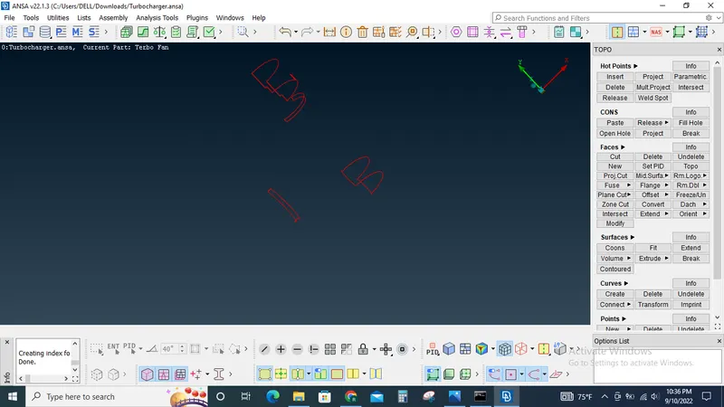
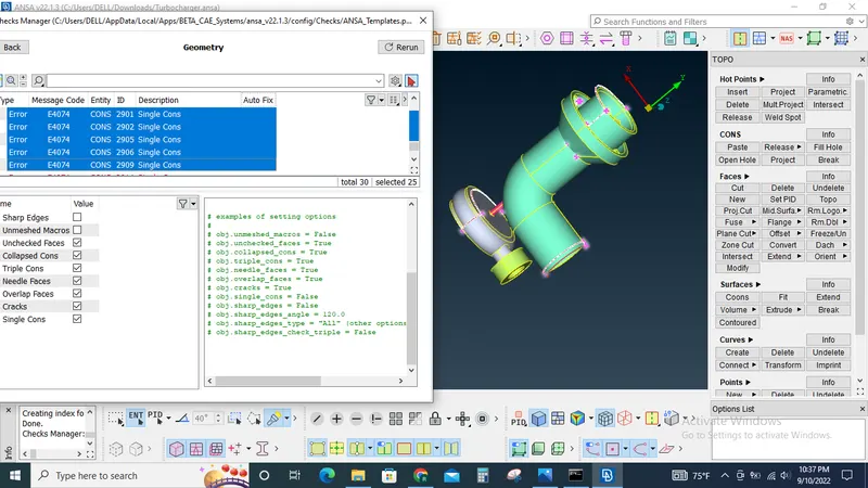
Now the single cons are identified by hiding the double cons, triple cons and shadow options. And also by performing the geometry checks.
The identified single cons are analysed and rectified one by one.
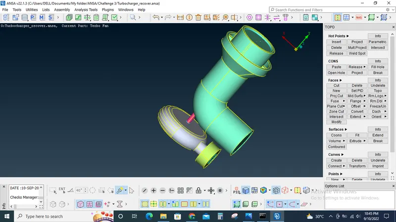
Now the model is cleaned so that only neccesary triple cons are available.
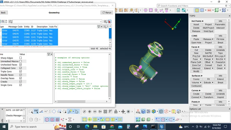
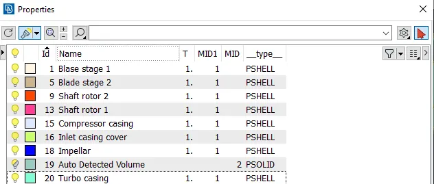
Now the required PID's are created and assigend to the respective regions using PID manager, PID selection filters.
Now surface meshing(tria) is done according to the given criterias
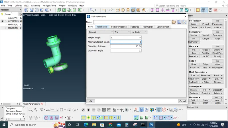
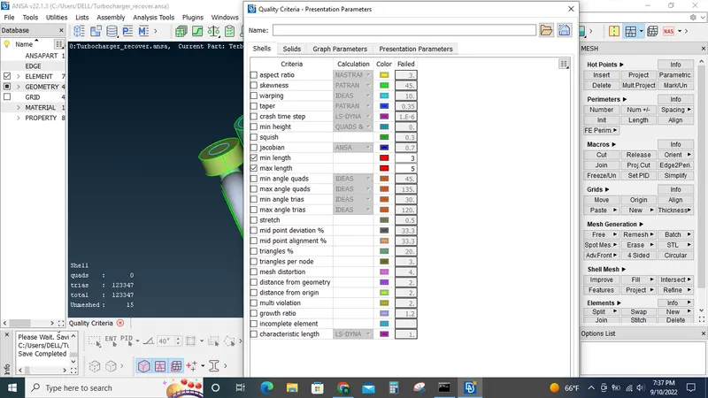
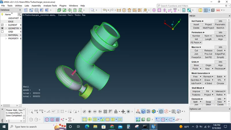
Blade stage-1 = 1 mm
Blade stage-2 = 1 mm
Impeller = 2 mm
Shaft rotor = 1 mm
Turbo casing = 5 mm
Compressor casing = 5 mm
Inlet casing cover = 5 mm
Once the surface mesh is done we can proceed with the volumetric mesh.
We start by defining the volume by using the define option under the volumes tab.
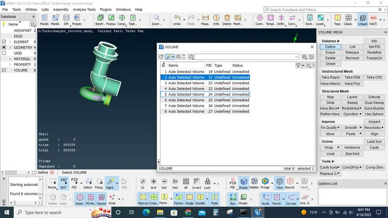
Once the automatic identification of available volumes is done we can delete the unnecessary volumes so that only the volumes that are needed are remaining.
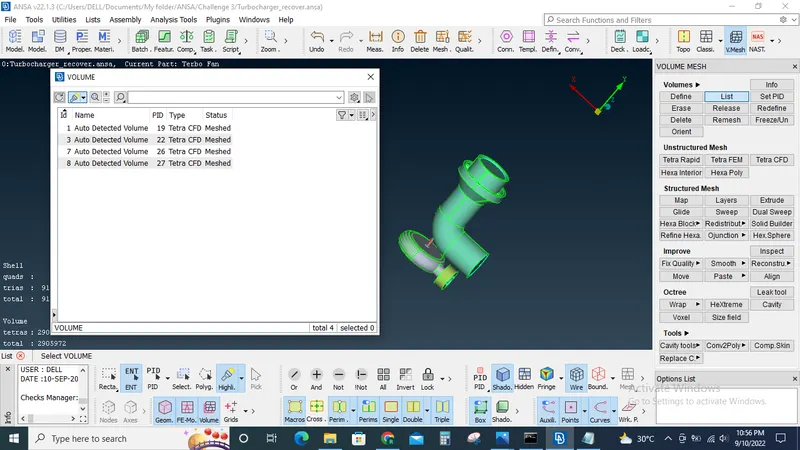
We can start creating the volumetric meshing by right clicking the volume and selecting remesh option, before that we should set the mesh type to tetra.
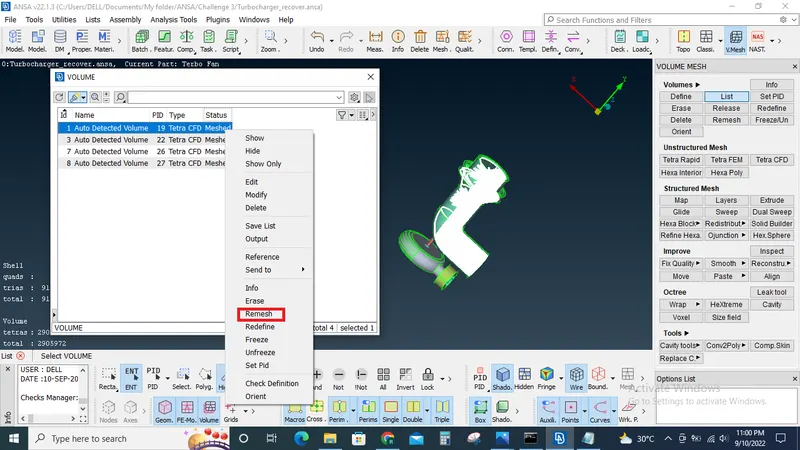
once all the volumes are meshed we can use the not option to verify the mesh quality by hiding some of the geometry.
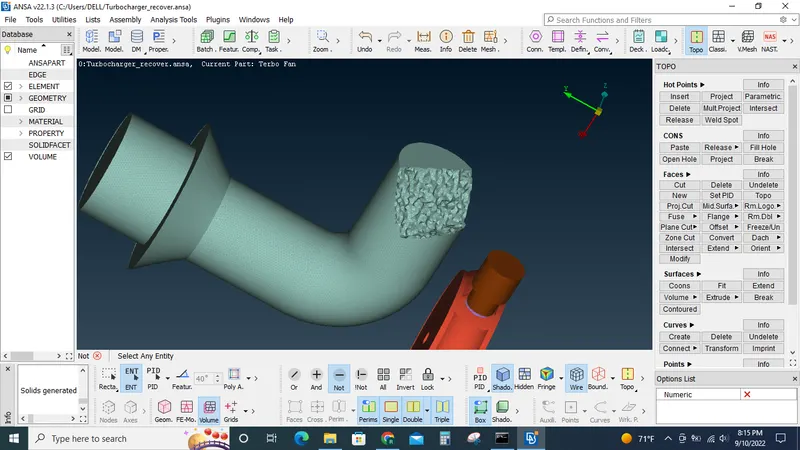
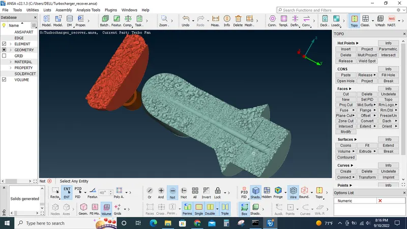
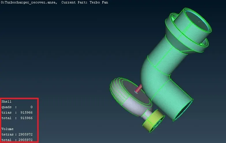
We can use the above status dashboard to make sure that there no unmeshed volume or surfaces.
Conclusion: Volumetric model is created in the given model according to the given criterias, It is observed that the volumetric meshes follows the surface mesh. Wherever the surface mesh was set as 1mm the mesh size around that region also follows the same size approximately. Simillarly for other mesh sizes also.
Tools used: Geometry checks,view tools, delete, release, project under cons, cut ,delete & intersect under faces, project, multi project, insert under hot points, mesh parameters, mesh quality tool, spot mesh, perimeters under length, define & list under volumes.
Outcome: Learned how to create volumetric mesh and its general prerequisites.