Week 9 - Parametric study on Gate valve.
Aim
To perform a parametric study on the gate valve simulation by setting the opening from 10% to 80%.
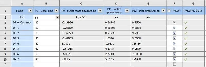
- Obtain the mass flow rate at outlet for each design points.
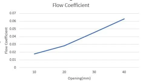
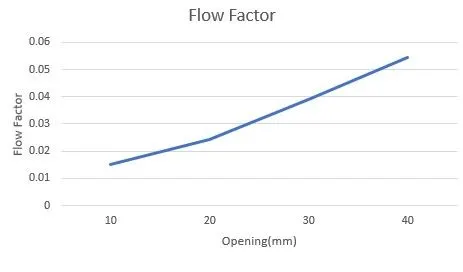
- Calculate the flow coefficient and flow Factor for each opening and plot the graph.
- Discuss the results of the mass flow rate and flow coefficient.
Introduction and Theory
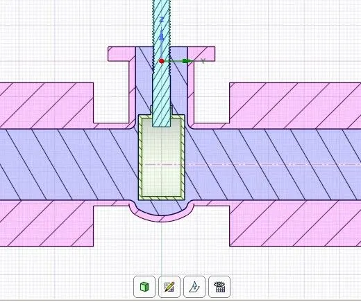
A gate valve, also known as a sluice valve, is a valve that opens by lifting a barrier (gate) out of the path of the fluid. Gate valves require very little space along the pipe axis and hardly restrict the flow of fluid when the gate is fully opened. The gate faces can be parallel but are most commonly wedge-shaped (in order to be able to apply pressure on the sealing surface). Gate valves are used to shut off the flow of liquids rather than for flow regulation, which is frequently done with a globe valve. Gate valves are mostly used with larger pipe diameters (from 2" to the largest pipelines) since they are less complex to construct than other types of valves in large sizes.
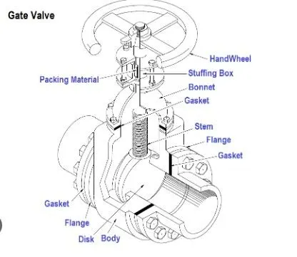
Common gate valves are actuated by a threaded stem that connects the actuator (e.g., handwheel or motor) to the gate. They are characterized as having either a rising or a non-rising stem, depending on which end of the stem is threaded. Rising stems are fixed to the gate and rise and lower together as the valve is operated, providing a visual indication of valve position. The actuator is attached to a rotating nut around the threaded stem to move it.
Bonnets provide leakproof closure for the valve body. Gate valves may have a screw-in, union, or bolted bonnet. A screw-in bonnet is the simplest, offering a durable, pressure-tight seal. A union bonnet is suitable for applications requiring frequent inspection and cleaning. It also gives the body added strength.
Equations used:
The mass flow rate is obtained from the solver and the discharge is calculated by dividing the mass flow rate by the density.
Q = m/rho
m- mass flow rate (kg/s)
rho- density (kg/m3)
Q – Discharge (m3/s)
The flow Coefficient is given by:
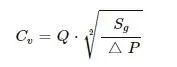
Sg – Specific gravity of the fluid
Del(P) – Pressure drop across the valve
Flow factor is given by:
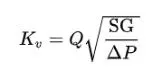
Flow Coefficient = 1.16 * Flow Factor
Solving and modeling Approach
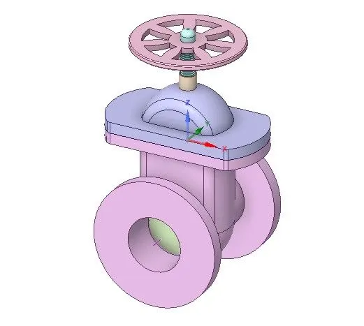
- Open Spaceclaim and load the geometry.
- Give a small movement to the gate disc and parameterize the ruler dimension.
- Extend the inlet and exit by 800 mm using the pull tool.
- Extract the fluid volume using the volume extract tool from prepare menu.
- Right-click volume and update the volume body in context.
- Suppress the solid geometries for physics.
- Open meshing and create a mesh with an element size of 10mm.
- Name the inlet and outlet of the geometry.
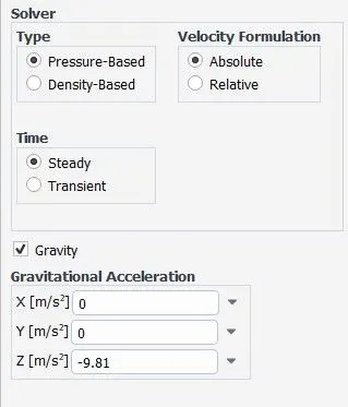
- In the solver enable gravity in the negative z direction and type in the value 9.81 m/s2.
- Using a steady state, pressure-based solver with absolute velocity formulation.
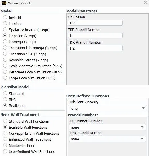
- A realizable k-epsilon viscous model with scalable wall function is used.
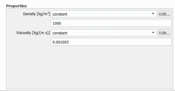
- Change the cell zone material to water.
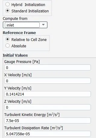
- Use pressure inlet as inlet boundary condition with a value of 10 pa.
- The outlet is kept as a pressure outlet.
- Define reports for mass flow rate and pressure values at desired locations and parameterize the calculation.
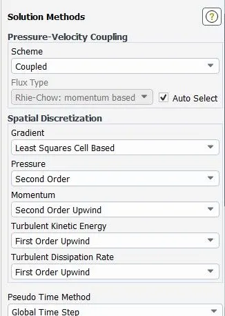
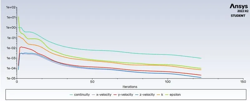
- A pressure velocity coupled solver is used and the setup is run for 250 iterations.
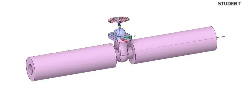
Pre-processing and solver settings
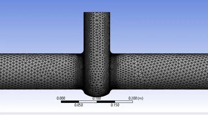
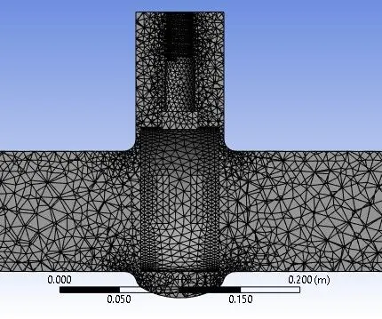
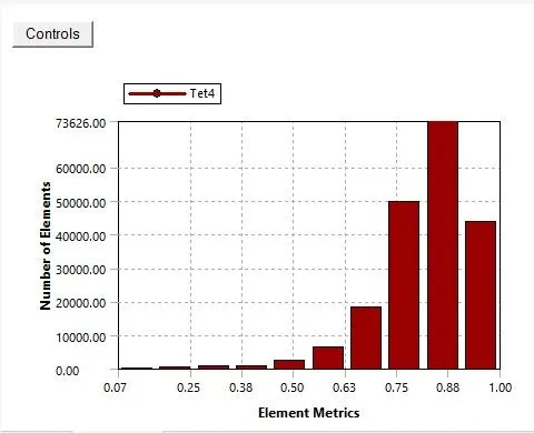

Results:
|
Sl No |
Opening (mm) |
Mass Flow Rate |
Pressure Drop |
Discharge |
Flow Factor |
Flow Coefficient |
|
1 |
10 |
0.14964 |
9.68274 |
0.00014964 |
0.015207176 |
0.017640324 |
|
2 |
20 |
0.23819 |
9.50035 |
0.00023819 |
0.024437328 |
0.028347301 |
|
3 |
30 |
0.37223 |
9.06864 |
0.00037223 |
0.039087716 |
0.04534175 |
|
4 |
40 |
0.47903 |
7.7662 |
0.00047903 |
0.054357369 |
0.063054548 |
|
5 |
50 |
6.3931 |
- |
0.0063931 |
- |
- |
|
6 |
60 |
0.64955 |
4.8831 |
0.00064955 |
0.092953293 |
0.107825819 |
|
7 |
70 |
1.3573 |
- |
0.0013573 |
- |
- |
|
8 |
80 |
8.9589 |
- |
0.0089589 |
- |
- |
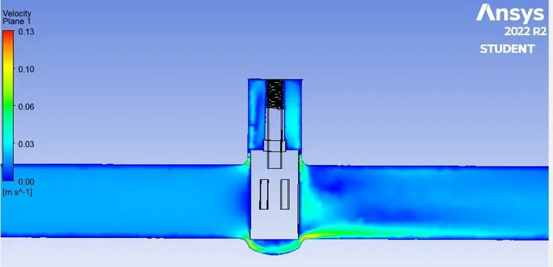
Conclusion
- A parametric study of the simulation of flow across the gate valve is performed and results are obtained.
- Mass flow rate and pressure values are taken as the parameters.
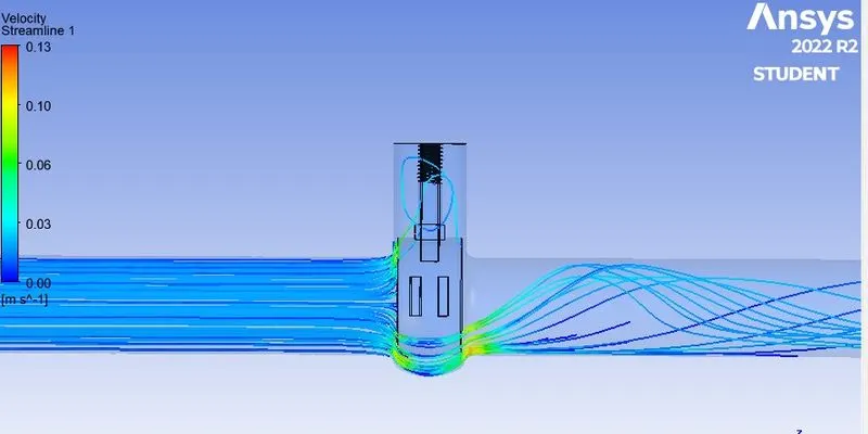
- The mass flow rate is found to increase with the increase in height of the gate disc as expected.
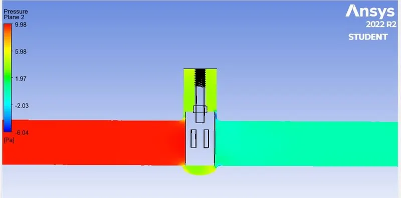
- The pressure drop across the gate disc decreases as height increases as expected.