Week 2 - Flow over a Cylinder.
Aim
Simulate the flow over a cylinder and explain the phenomenon of Karman vortex street.
PART-I
- Simulate the flow with the steady and unsteady case and calculate the Strouhal Number for Re= 100.
PART-II
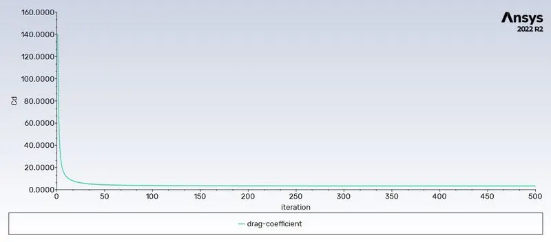
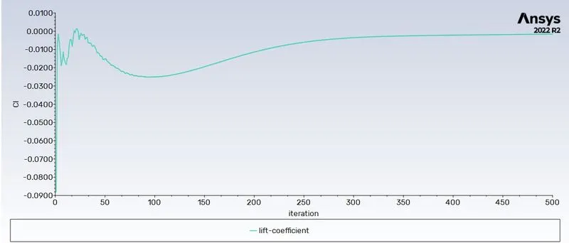
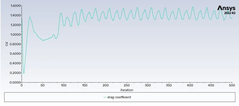
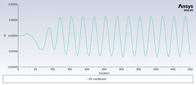
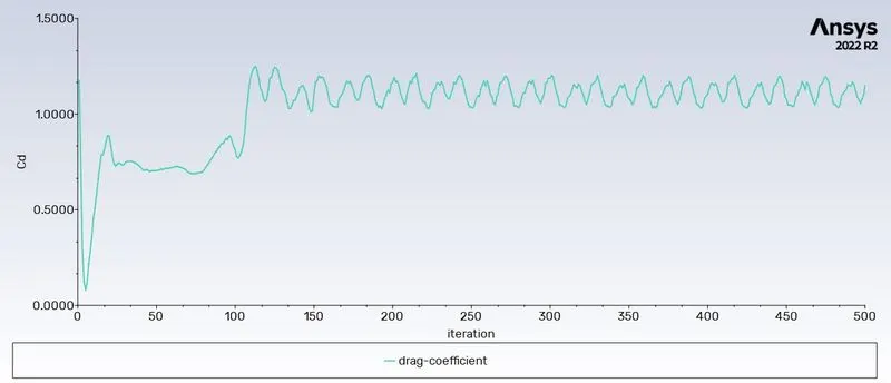
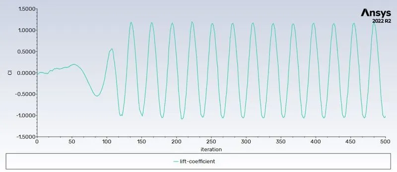
- Calculate the coefficient of drag and lift over a cylinder by setting the Reynolds number to 10,100,1000,10000 & 100000. (Run with steady solver)
- Discuss the effect of Reynolds number on the coefficient of drag.
Introduction
Cross-flow normal to the axis of a stationary circular cylinder and the associated problems of heat and mass transport are encountered in a
wide variety of engineering applications. Both experimental measurements and numerical computations have confirmed the onset of instability of the wake flow behind a cylinder beyond a critical Reynolds number, leading finally to a kind of periodic flow identified by definite frequencies, well-known in the literature as the Von Karman vortex street. In case of laminar flow past cylinders with regular polygonal cross-section, the flow usually separates at one or more sharp corners of the cross-section geometry itself, forming a system of vortices in the wake on either side of the mid symmetry plane. On the other hand, for a circular cylinder, where the point of flow separation is decided by the nature of the upstream boundary layer, the physics of the flow is much more complex than what its relatively simple shape might suggest.
Theory
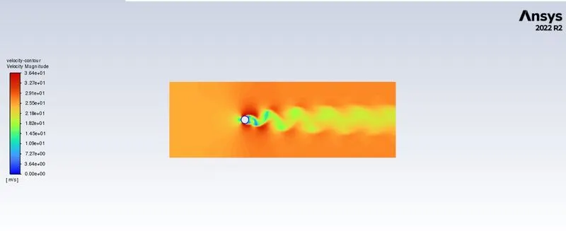
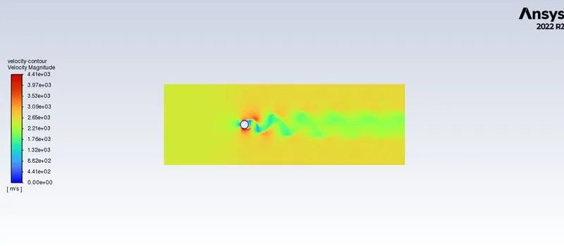
Beyond a critical Reynolds number of about 49, the steady closed near wake becomes unstable and a transverse oscillation starts near the end of the wake. As the Re is increased further, the vortices are shed alternately from the upper and lower cylinder surface at a defifinite frequency depending on the Reynolds number.

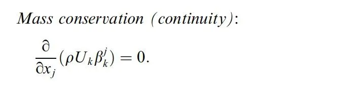
Solving and modelling approach
- The model is designed as per the specifications in Spaceclaim.
- Generate the surface from the line sketch, delete the circle from the domain.
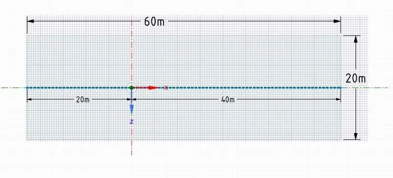
- The circle is of 2m diameter.
- After completion of the geometry creation the geometry is loaded for meshing.
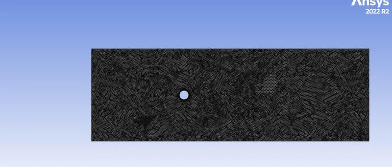
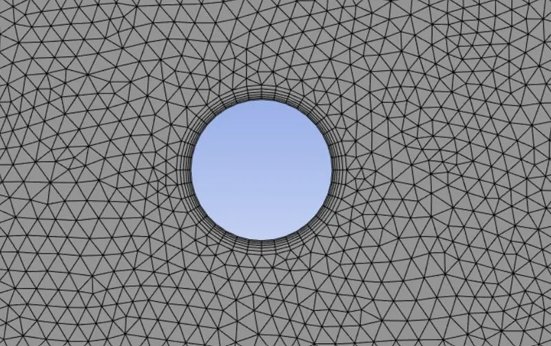
- Triangular mesh is selected with 6 inflation layers around the circle as well as edge sizing of the circle is performed.
- Go to setup and select pressure based solver, absolute velocity formulations, steady, and viscous model as laminar.
- Create a new user material with density 1kg/m^3 and viscosity 0.05 Pa-s.
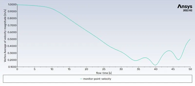
- Choose a monitor point at four times the diameter of the circle.
- Use hybrid initialisation .
- Solve the setup to get the desired output.
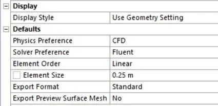
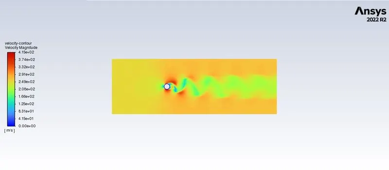
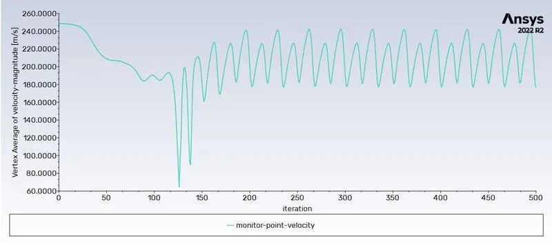
- On solving it is observed that the phenomenon of vortex shredding is not reflected properly so element size is reduced to 0.25 m in meshing and run the problem for more number of iterations.
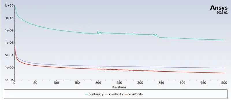
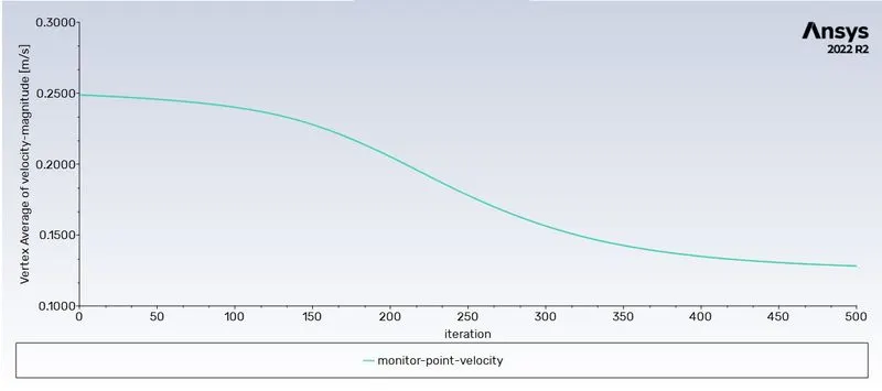
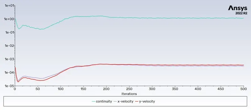
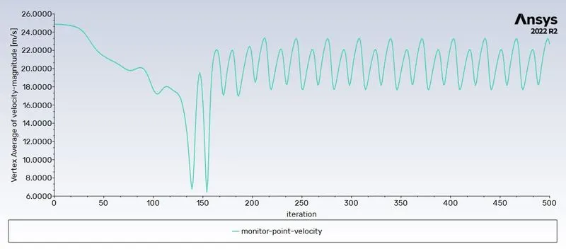
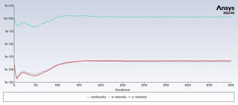
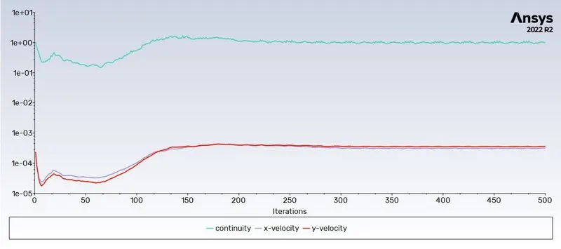
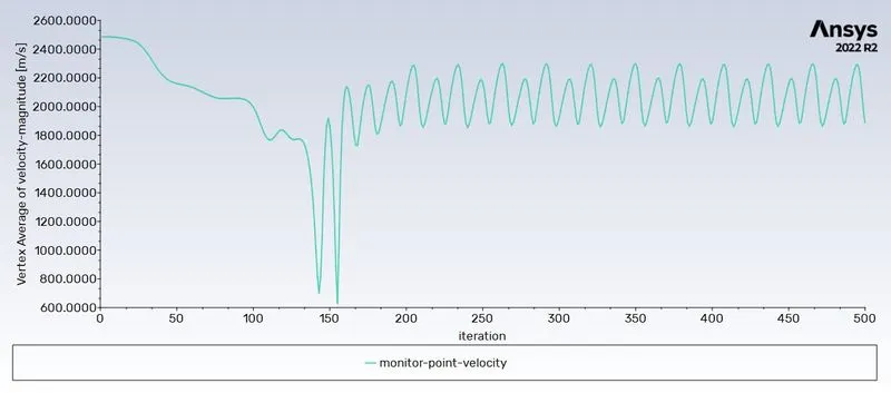
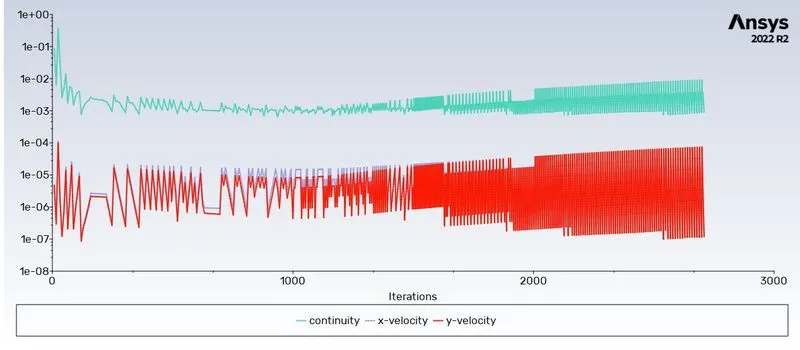
- The number of iterations is continued until a steady periodic solution is obtained.(convergence)
- The above result can be observed by monitoring Residuals as well the vertex average velocity at monitor point.
- The experiment is run at different Reynolds number by changing the velocity and steady state solutions are obtained.
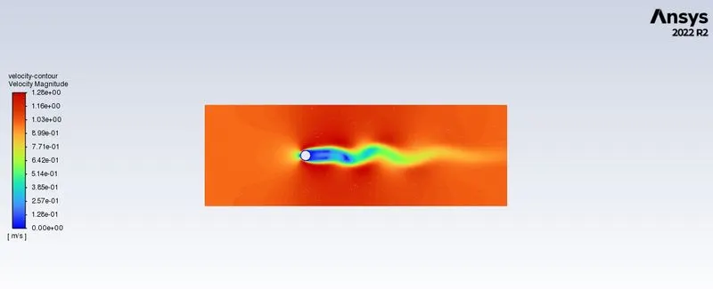
- For Re=100 both steady and transient state solution is obtained .
- The transient solution is obtained by taking a time step 0.1.
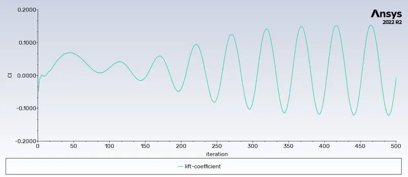
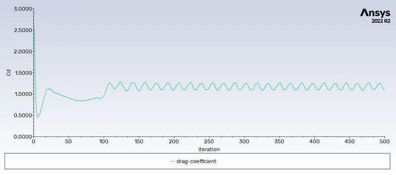
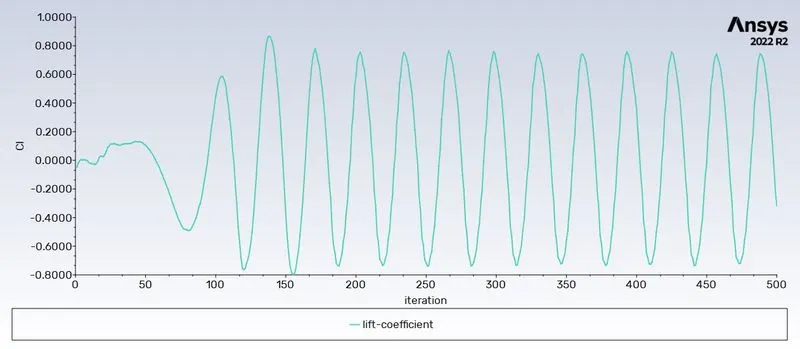
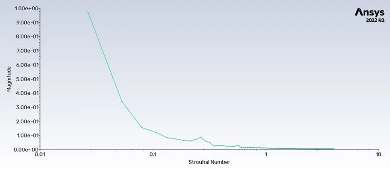
- The Strouhal number for Re=100 is obtained by taking the FTT of the plot.
Setup and mesh
-

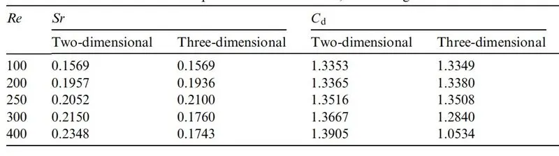
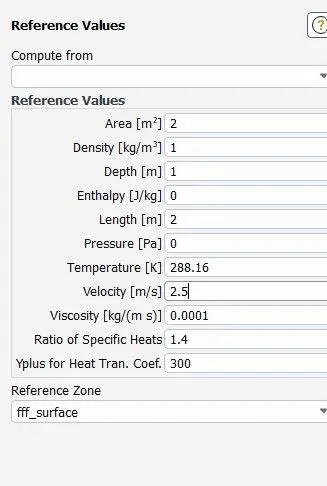
Reference value example for drag and lift calculation:
Contours and plots
Re=10
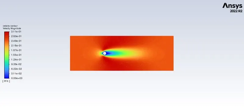
Re=100
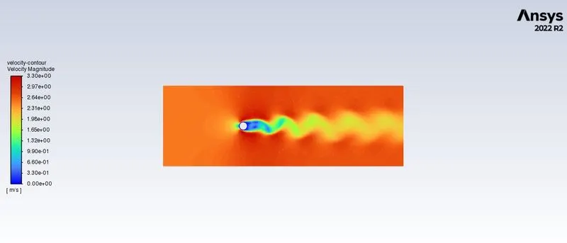
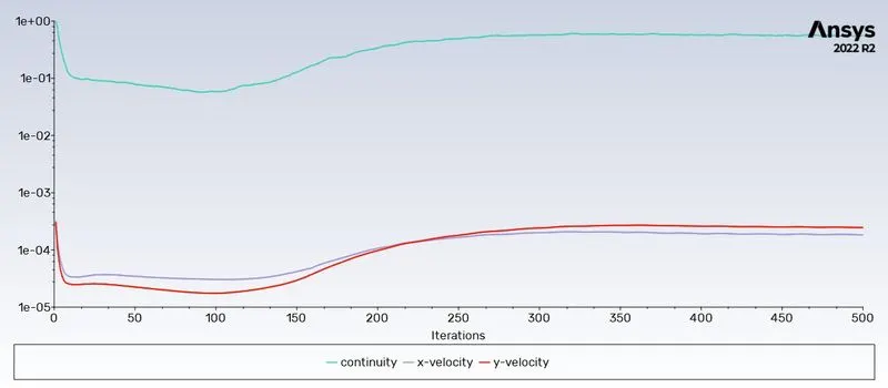
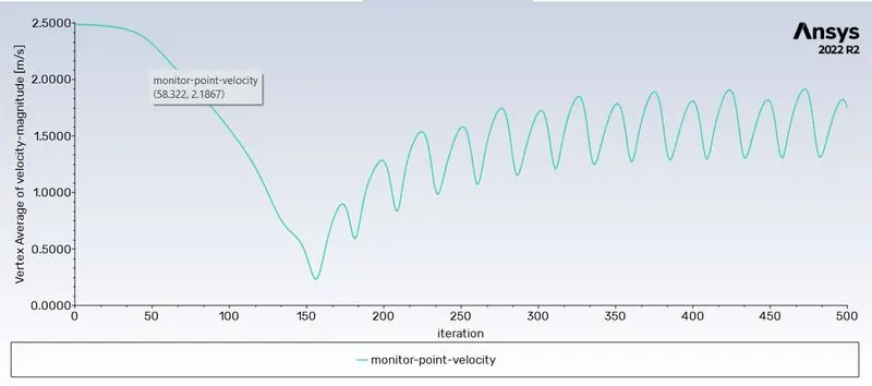
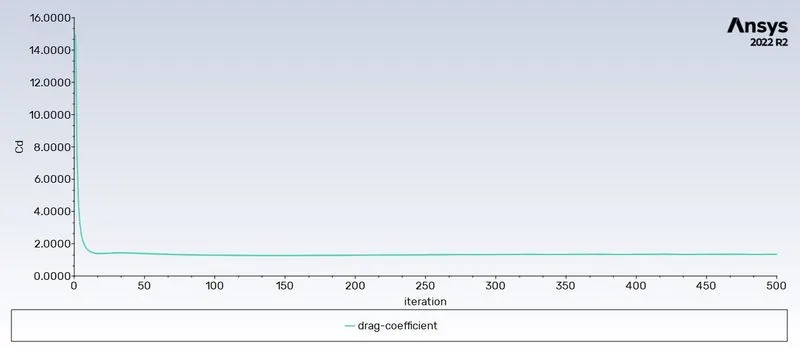
Re=1000
Re=10000
Re=100000
Transient solution
Results:
- Strouhal Number for Reynolds number 100 = 3.987
|
Reynolds Nmber |
Coefficient of drag |
Coeffcient of Lift |
|
10 |
3.3274189 |
0.001581305 |
|
100 |
1.3470217 |
0.006513078 |
|
1000 |
1.0954054 |
0.32448671 |
|
10000 |
1.3399958 |
1.2025663 |
|
100000 |
1.1486238 |
1.0168934 |
Conclusion
The transient solution is more efficient in capturing the vortex shredding for flow over the cylinder. The flow will attain a steady periodic state after some time. The frequency of the oscillation will remain fixed after that. The coefficient of drag decreases with increasing in the Reynolds number . This is due to the delay in flow seperation at high reynolds number. The drag decreases at high Reynolds number while the lift increases at high Reynolds number.The drag later increases at high Reynolds number.This might be because of the use of use of Laminar viscous model at high Reynolds number.
Reference of Cd: