Week 9 - Parametric study on Gate valve.
Aim: To perform simulation on the gate valve using parametric study for opening from 10 % to 80 % and obtain mass flow rate at outlet, flow coefficient and flow factor.
Introduction: Gate valves are used in the piping industries for dealing with liquids and gases. It is used only for opened and closed condition only. It is not used to regulate the flow or throttle the flow; because the amount of the flow through valve is not proportional to the amount of opening of the gate; therefore it is used only for fully opened or fully closed position. If the gate valve is used for throttling condition it can cause erosion to the disc because of the higher velocity in partially opened valves. It is commonly used in in -line position only, only accassionally we will close the disc, thereby isolating the piping system. Generally it is better to have disc opened fully, implies less resistance to the flow which indicated lower pressure drop. The discs can be either inclined or parallel. The inclined disc can be again either solid wedge, split wedge or flexible wedge disc. A bonnet is there which is connected to the valve body , is of same material as the valve body and is attached with help of threaded bolt.
Theory: There is a stem which connects between the disc and the handwheel. There are generally two types of gate valves: Rising stem gate valves and non rising stem gate valve. In rising stem gate valve, we can see the stem rising above the handwheel as the disc is getting opened and will fall down through the handwheel when the disc is getting closed. The advantage of rising type gate valve is that we can visually tell whether the gate is open or close from outside by seeing the stem position above the handwheel; while the disadvantage is that as the stem lowers down there is chance some dirt may enter which can even enter the seals and cause damage and leaking. In typical gate valve applications we will consider the service temperature is about -20 degree centigrade to 60 degree centigrade, maximum pressure is about 16 bar while the flow speed is about 5 to 20 m/sec. For liquids we may consider flow about 5 m/sec while for gas maximum speed is about 20 m/sec.
The majority of the components are made of corrosion resistance material like stainless steel spindle or stem. The disc can also be vulcanised to have corrosion resistance. Here in this project we consider actuation by handwheel. Other actuations are also possible like operating cap, extension spindles and electric actuator. The disc may have to withstand high pressure when in closed condition; therefore it requires great strength and is usually forged and hard surfaced.
Valve flow coefficient (Cv) is the flow capability of the control valve at fully opened conditions relative to pressure drop across the valve. It is defined as volume of water (GPM in US ) at 60°F that will flow through a fully open valve with a pressure differential of 1 psi across the valve. It is useful to know how to calculate Cv because it is the standardized valve sizing and selection method for control valves used throughout the HVAC industry. It is based on the imperial unit systems.
The equation used to find Cv is
Cv = Q * sqrt (S) / sqrt (ΔP )
where Q is flow in gallons per minute
S = specific gravity of fluid ( 1 for water )
ΔP = pressure differential over valve in psi.
Flow factor (Kv) : is defined as the flow of water with temperature ranging from 5 - 30 oC through a valve in cubic metres per hour with a pressure drop of 1 bar. It is based on the S I units system.
Kv = Q * sqrt (S) / sqrt (ΔP )
where Q is flow in metre cube per hour
S = specific gravity of fluid ( 1 for water )
ΔP = pressure differential over valve in bar.
Solving and modelling approach:
The geometry is downloaded and then imported to the spaceclaim of the Fluent from Ansys workbench. Then we will perform the pull operation on both sides to 800 mm each. Then from the sketch we will select the move option and select the valve body. Then we will move the z direction in positive 10 mm . Then go to the groups and select new parameter then it is created. Then we will do the volume extract so that we can fill the valve body with the fluid domain. It is completed then we will suppress the solid domains, and use only fluid domain for further processing. Now we will do the meshing, we go with the default mesh. Then the inlet and outlet named selections are given and the mesh quality is checked. Now we will go to the Ansys fluent solver. We will do pressure based solver and gravity enabled in Z direction as -9.81 m/s2, as geometry is aligned that way. Then the turbulence model is given, k epsilon RNG standard wall function with swirl dominated enabled. Then water is given in the materials. Then the surface report of mass flow rate is created and then the intialization is done( hybrid). Then the solution is run for 350 itertions to see solution convergence. Now the residual plots are created. After getting results , we select the parameter option, and click on 20 mm value. Then retained option is enabled, and design point2 is updated. Then automatically the geometry is updated, similarly meshing and solving is done, and mass flow rate result is obtained. Now right click on dp2 and select current , now we will see the contour plot of this. Repeat the procedure till we will do the lift of gate as 80mm, then calculate the flow coefficient and flow parameter.
Preprocessing and solver setting:
(i) Geometry creation
The geometry is imported to the spaceclaim of ansys workbench. Then we will extend to 800mm each side, then move option used to create parameter as lift of the disc, then using volume extract we will add fluid domain.
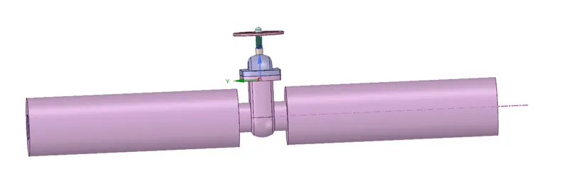
Fig 1 : Geometry of model
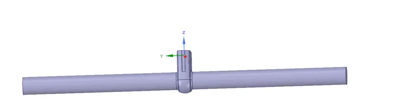
Fig 2 : fluid volume inside solid
(ii) Meshing
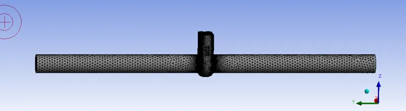
Fig 3 : Meshing of fluid domain
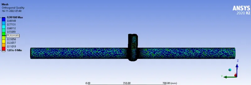
Fig 4 : orthogonal quality check of mesh
(iii) Fluent solver
We will do pressure based solver with gravity as -9.81m/s2 in z direction because of geometry alignment.
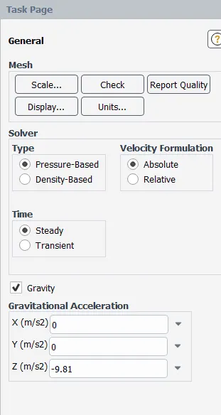
Fig 5 selecting pressure based model
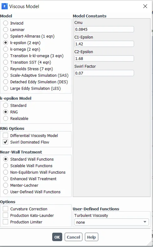
Fig 6 selecting turbulence model
K epsilon RNG turbulence model with standard wall function selected, with swirl dominated flow.
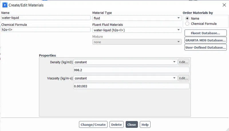
Fig 7 selecting water as fluid material
Then the boundary conditions are given. First we will give pressure inlet boundary condition.
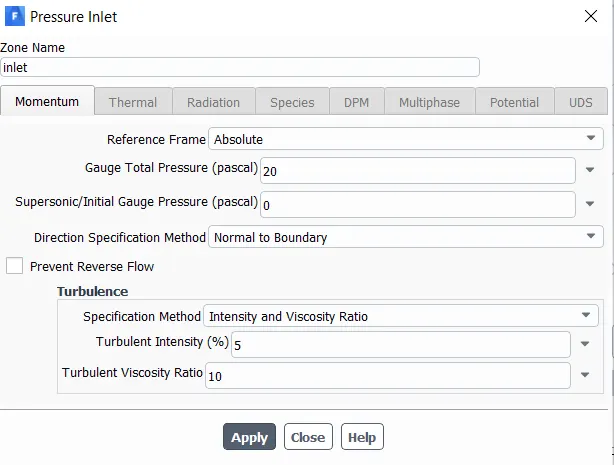
Fig 8 selecting pressure inlet boundary condition
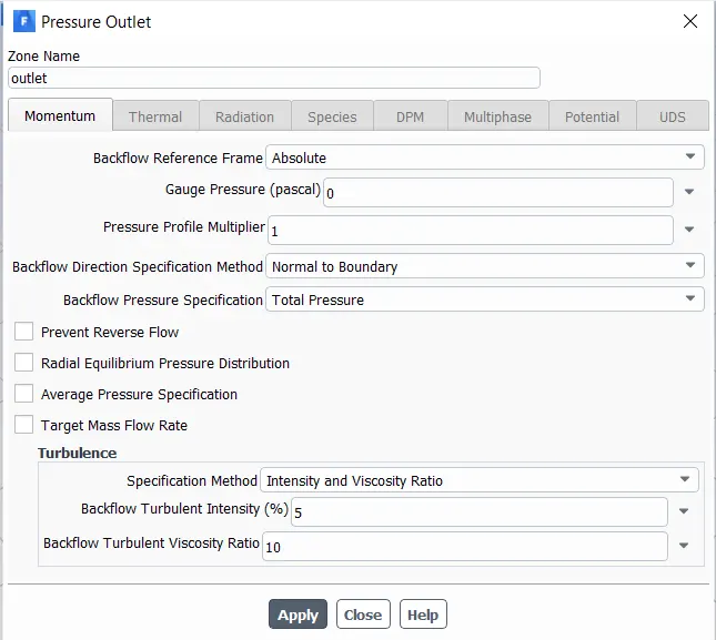
Fig 9 selecting pressure outlet boundary condition
Now we will create surface report of mass flow rate at outlet.
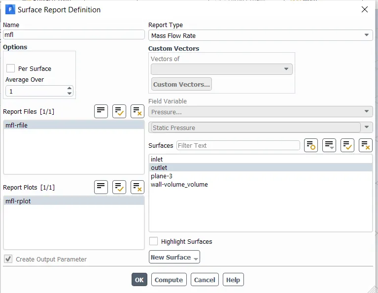
Fig 10 selecting mass flow rate surface report
now we will do solution intialization.
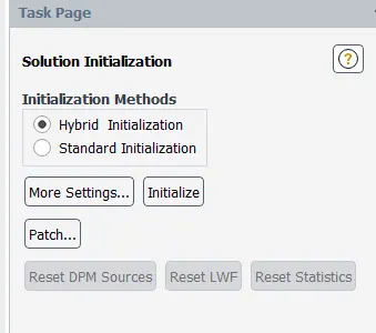
Fig 11 selecting hybrid intialization
Now we will run for 350 iterations till we get convergence.
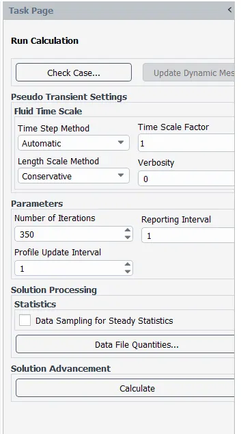
Fig 12 running solution
Results:
(i) Residual plots
(a) Gate lift of 10 mm.
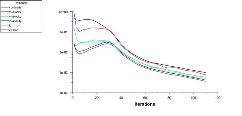
Fig 13 residual plot for case 1
(b) Gate lift of 20 mm
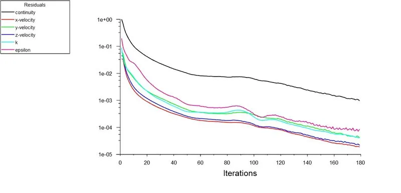
Fig 14 residual plot for case 2
(c) Gate lift of 30 mm
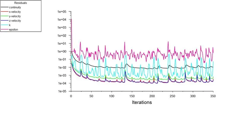
Fig 15 residual plot for case 3
(d) Gate lift of 40 mm
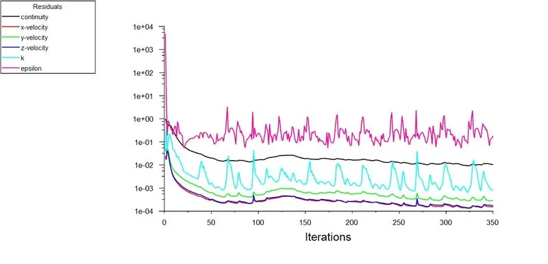
Fig 16 residual plot for case 4
(e) Gate lift of 50 mm
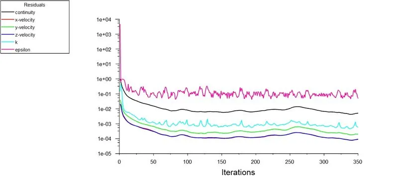
Fig 17 residual plot for case 5
(f) Gate lift of 60 mm
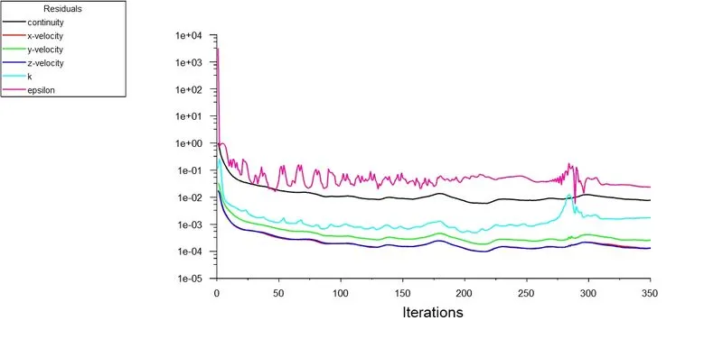
Fig 18 residual plot for case 6
(g) Gate lift of 70 mm
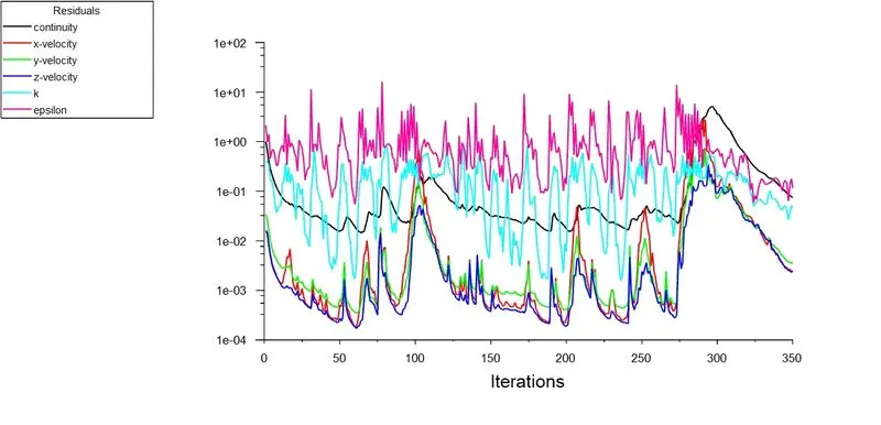
Fig 19 residual plot for case 7
(h) Gate lift of 80 mm
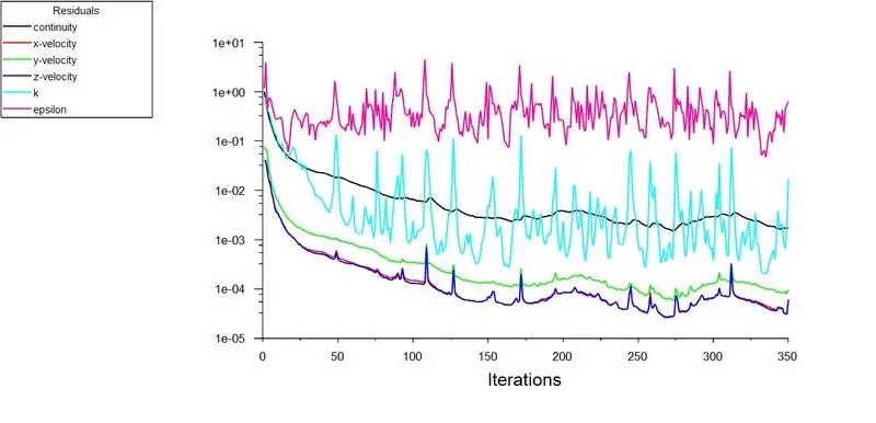
Fig 20 residual plot for case 8
(ii) Mass flow rate at outlet
(a) Gate lift of 10 mm
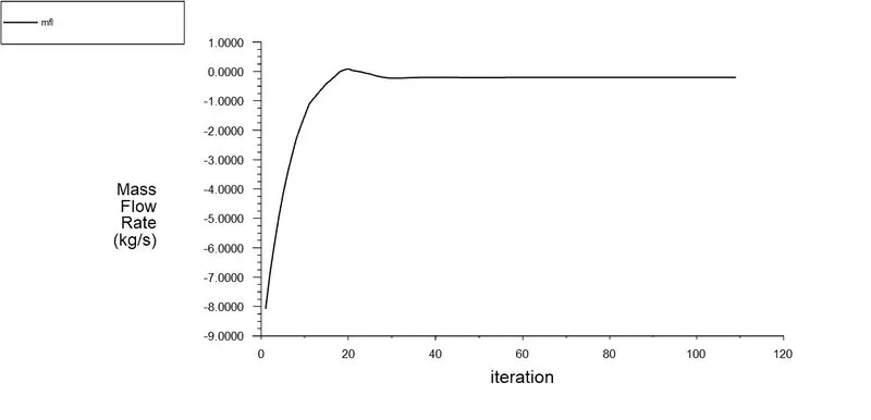
Fig 21 mass flow rate for case 1
(b) Gate lift of 20 mm
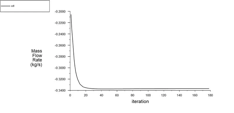
Fig 22 mass flow rate for case 2
(c) Gate lift of 30 mm
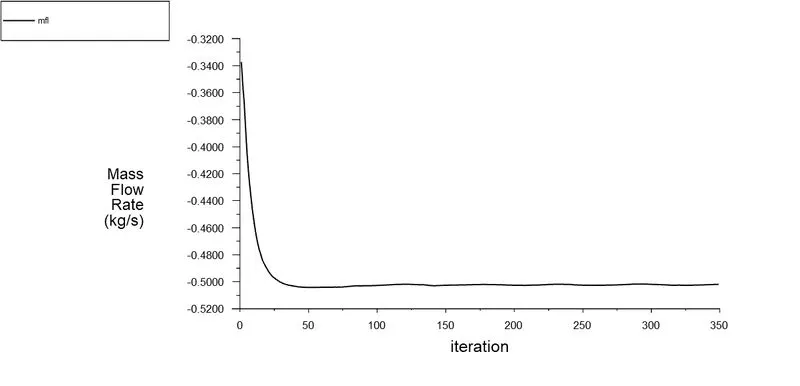
Fig 23 mass flow rate for case 3
(d) Gate lift of 40 mm
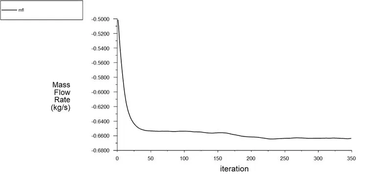
Fig 24 mass flow rate for case 4
(e) Gate lift of 50 mm
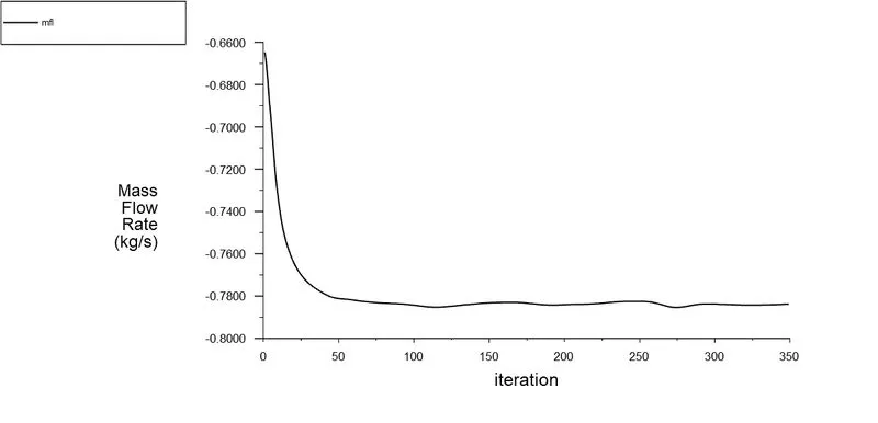
Fig 25 mass flow rate for case 5
(f) Gate lift of 60 mm
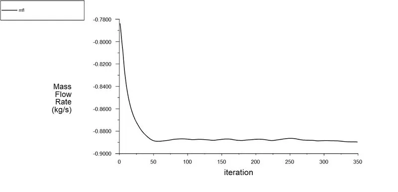
Fig 26 mass flow rate for case 6
(g) Gate lift of 70 mm
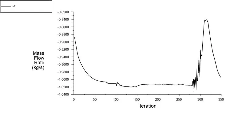
Fig 27 mass flow rate for case 7
(h) Gate lift of 80 mm
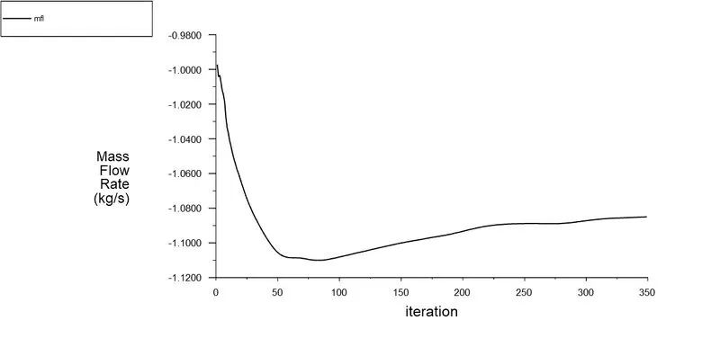
Fig 28 mass flow rate for case 8
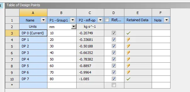
Fig 29 Showing parametric form of the design points
Conclusions:
We have performed simulation on the gate valve problem by parameterising the lift of the disc. We have given lift from 10 mm to 80 mm and obtained the mass flow rate, and calculated the flow coefficient Cv and flow factor Kv.
| S. No | Gate lift (mm) | Mass flow rate (kg/sec) | Flow coefficient Kv | Flow factor Cv |
| 1 | 10 | 0.207 | 0.166 | 60.9 |
| 2 | 20 | 0.33 | 0.265 | 97.06 |
| 3 | 30 | 0.5 | 0.40 | 146.99 |
| 4 | 40 | 0.66 | 0.528 | 193.58 |
| 5 | 50 | 0.78 | 0.62 | 228.65 |
| 6 | 60 | 0.88 | 0.70 | 258.16 |
| 7 | 70 | 0.99 | 0.79 | 290.83 |
| 8 | 80 | 1.08 | 0.865 | 317 |
- From the table it is found that the flow rate increases with the gate lift. As the disc is opened, the resistance to the flow decreses hence the pressure drop decreases.
- The flow coefficient Cv(Imperial units) and flow factor Kv (S I units) both increases with the gate lift, which is implying rise in the flow rate for the same pressure drop across valve.
- The gate valve should be used only in fully opened or fully closed condition, should not be used for throttling.