Week 9 - Parametric study on Gate valve.
Aim
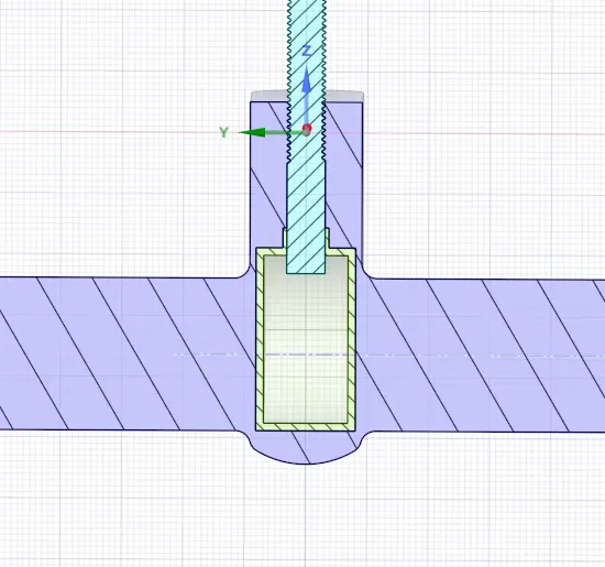
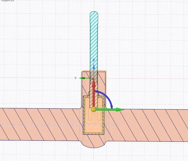
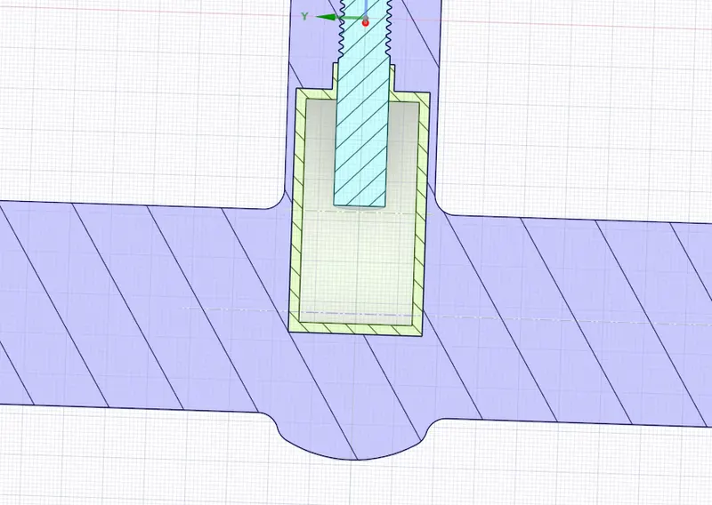
Performing a parametric study on the gate valve simulation by setting the opening from 10 % to 80%.
Introduction
A gate valve, also known as a sluice valve, is a valve that opens by lifting a barrier (gate) out of the path of the fluid. Gate valves require very little space along the pipe axis and hardly restrict the flow of fluid when the gate is fully opened. The gate faces can be parallel but are most commonly wedge-shaped.
Gate valves are used to shut off the flow of liquids rather than for flow regulation. When fully open, the typical gate valve has no obstruction in the flow path, resulting in very low flow resistance. The size of the open flow path generally varies in a nonlinear manner as the gate is moved. This means that the flow rate does not change evenly with stem travel. Depending on the construction, a partially open gate can vibrate from the fluid flow.
1.Typical Use
Gate valves are mostly used with larger pipe diameters (from 2" to the largest pipelines) since they are less complex to construct than other types of valves in large sizes.
At high pressures, friction can become a problem. As the gate is pushed against its guiding rail by the pressure of the medium, it becomes harder to operate the valve. Large gate valves are sometimes fitted with a bypass controlled by a smaller valve to be able to reduce the pressure before operating the gate valve itself.
Gate valves without an extra sealing ring on the gate or the seat are used in applications where minor leaking of the valve is not an issue, such as heating circuits or sewer pipes.
2.Valve Construction
Common gate valves are actuated by a threaded stem that connects the actuator (e.g. handwheel or motor) to the gate. They are characterised as having either a rising or a nonrising stem, depending on which end of the stem is threaded. Rising stems are fixed to the gate and rise and lower together as the valve is operated, providing a visual indication of valve position. The actuator is attached to a nut that is rotated around the threaded stem to move it. Nonrising stem valves are fixed to, and rotate with, the actuator, and are threaded into the gate. They may have a pointer threaded onto the stem to indicate valve position, since the gate's motion is concealed inside the valve. Nonrising stems are used where vertical space is limited.
Gate valves may have flanged ends drilled according to pipeline-compatible flange dimensional standards.
Gate valves are typically constructed from cast iron, cast carbon steel, ductile iron, gunmetal, stainless steel, alloy steels, and forged steel.
All-metal gate valves are used in ultra vaccum chambers to isolate regions of the chamber.
Objectives & Results
Flow Coefficient
It is the relative measure of its efficiency at allowing fluid flow. It describes the relationship between the pressure drop across the orifice valve or other assembly and the corresponding flow rate.
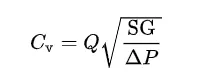
Here,Q is the mass flow rate in gal/min
SG is the specific gravity of fluid
`Delta P` is the pressure drop across the valve in psi
Flow factor
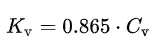
The flow factor of a valve indicates,"The water flow in m^3/h , at a pressure drop across the valve of 1kgf/cm^2 when the valve is completley open.
Meshing
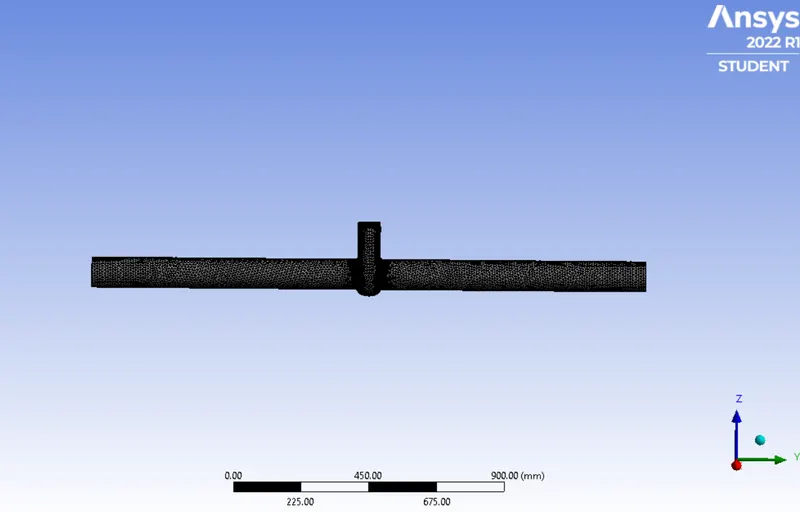
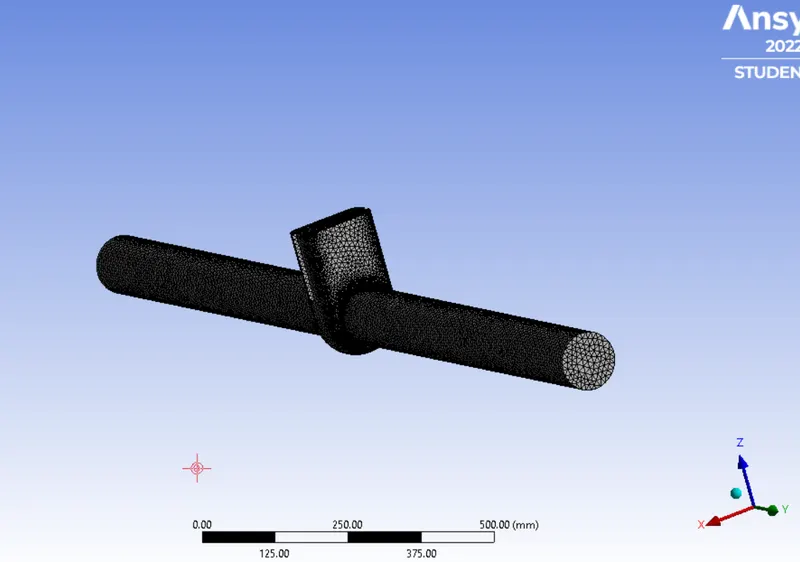
Mesh size = 10mm
Total elements = 193242
Note:The values below are 10mm less than the actual value i.e the actual value starts from 20mm upto 70mm lift.
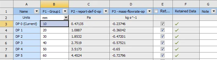 Inlet pressure = 10pa = 0.00145 psi
For 10mm lift
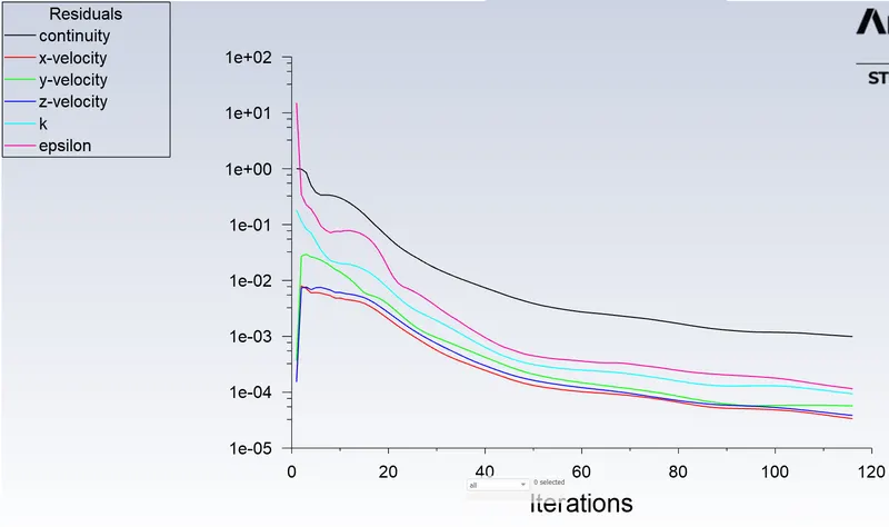
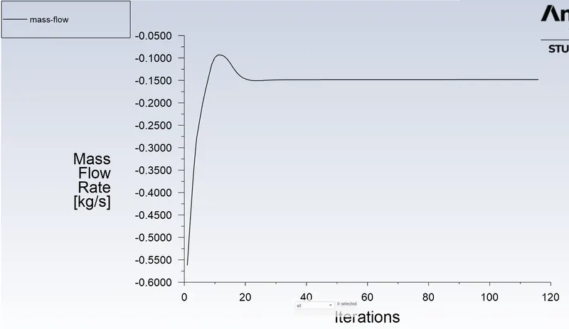
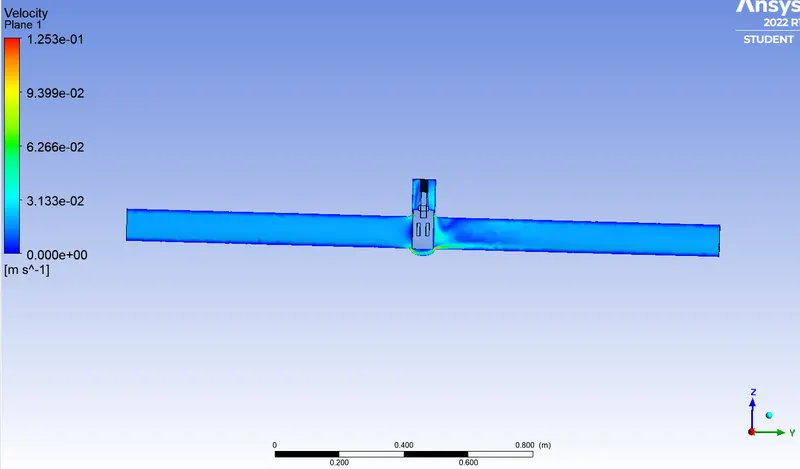
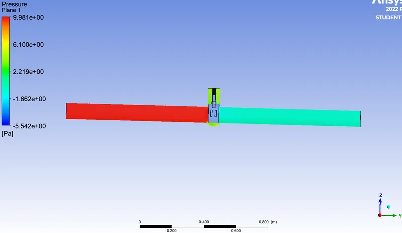
Mass flow rate = -0.148 kg/s = -2.35 gal/min
Outlet pressure = 0.184 Pa = 0.000026 psi
Flow coefficient = 68.12
Flow factor = 58.92
For 20mm lift
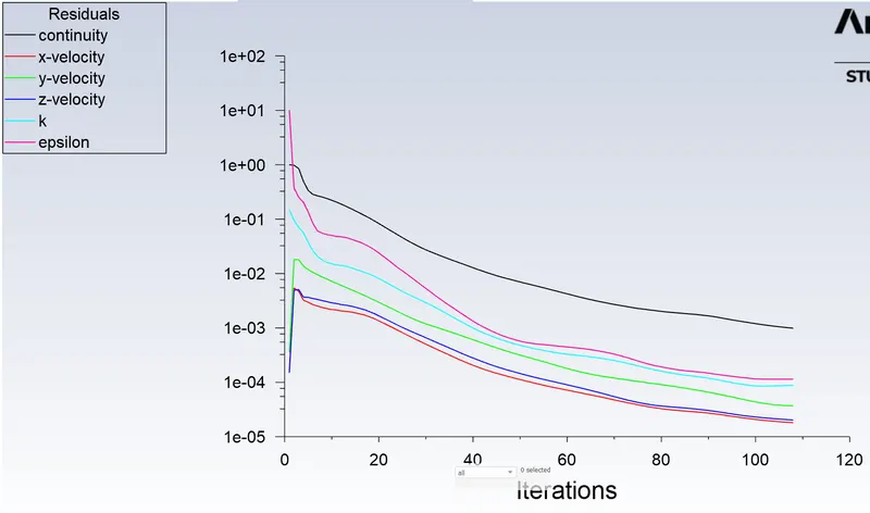
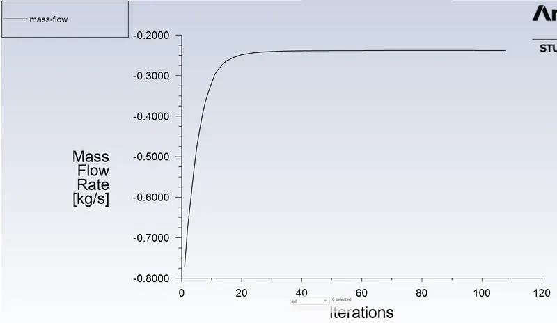
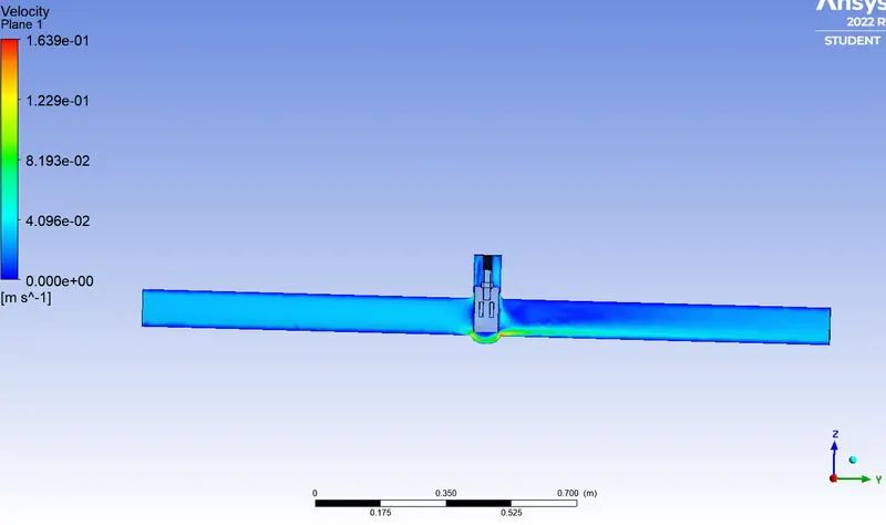
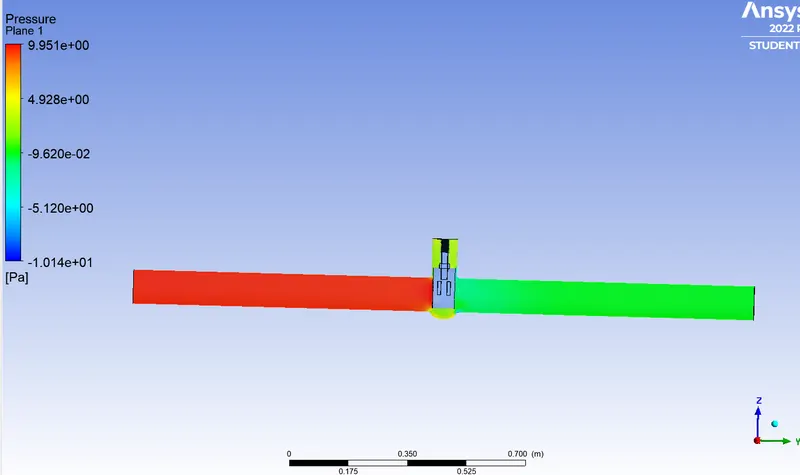
Mass flow rate = 0.23746 kg/s = -3.76 gal/min
Outlet pressure = 0.47135 Pa = 0.00006836 psi
Flow coefficient = 101.14
Flow factor = 87.48
For 30mm lift
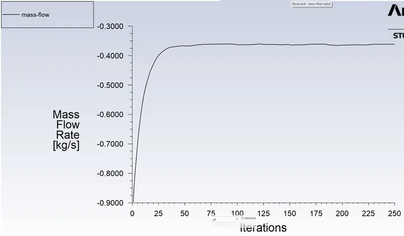
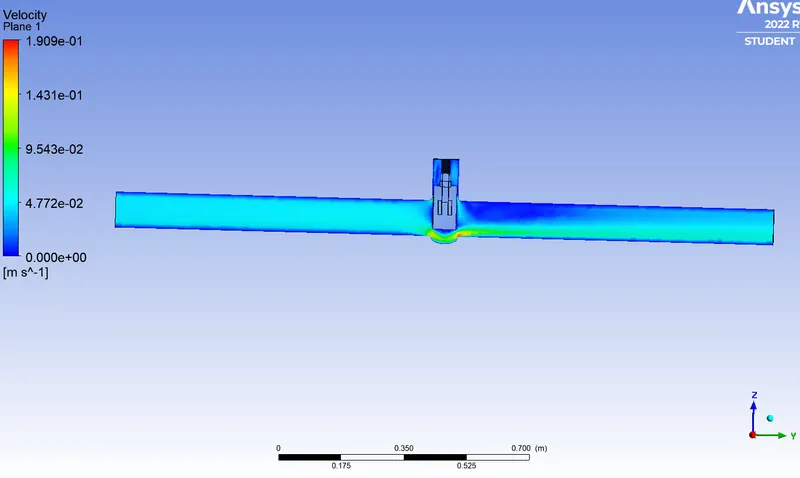
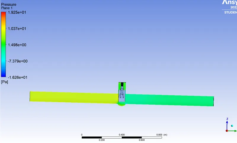
Mass flow rate = -0.36042 kg/s = -5.17gal/min
Outlet pressure = 1.0887 Pa = 0.0001579 psi
Flow coefficient = 143.82
Flow factor = 124.40
For 40mm lift
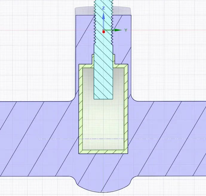
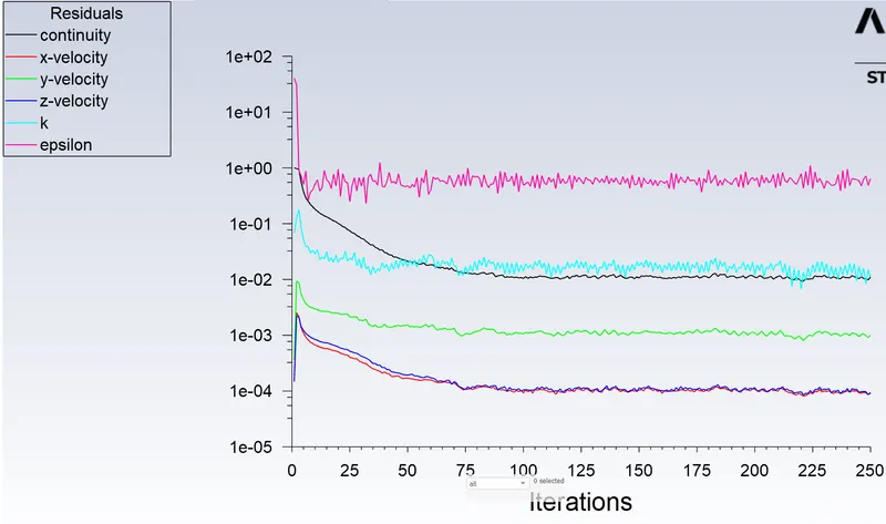
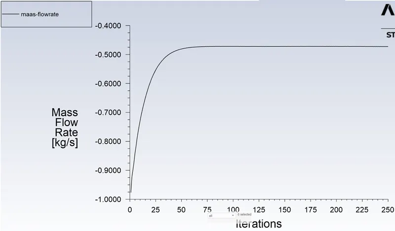
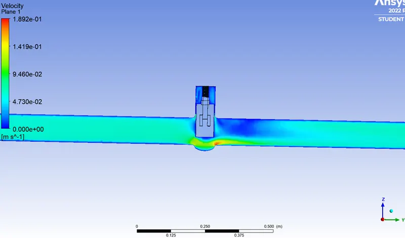
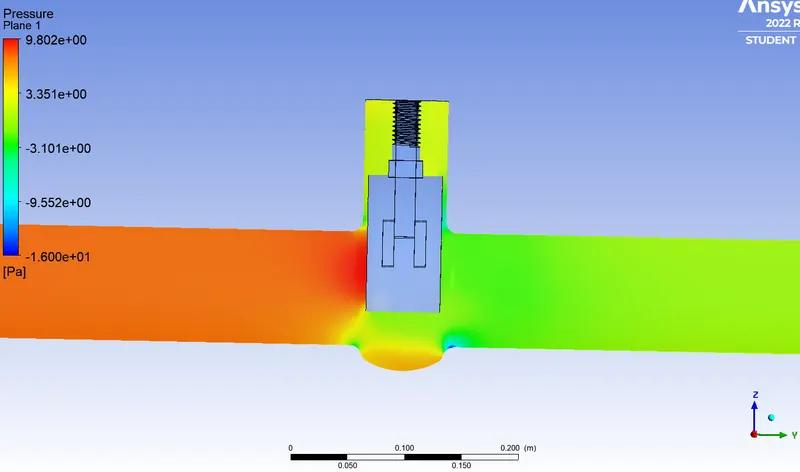
Mass flow rate = -0.47201 kg/s = -7.48 gal/min
Outlet pressure = 1.8532 Pa = 0.0002687 psi
Flow coefficient = 217.63
Flow factor = 188.24
For 50mm lift
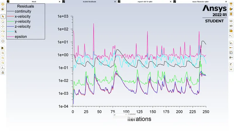
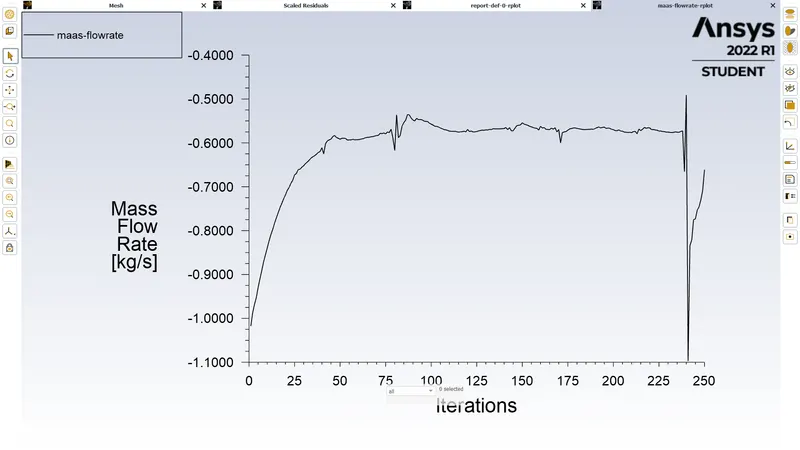
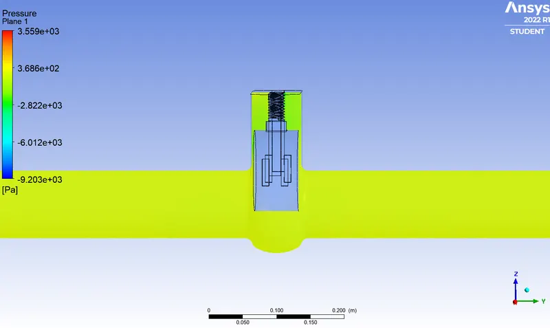
Mass flow rate = -0.57521 kg/s = -9.12 gal/min
Outlet Pressure = 2.7519 Pa = 0.0003976 psi
Flow coefficient = 281.12
Flow factor = 243.16
For 60mm lift
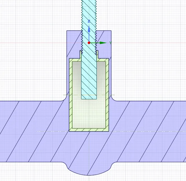
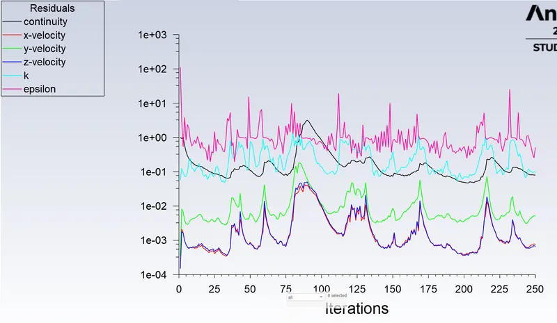
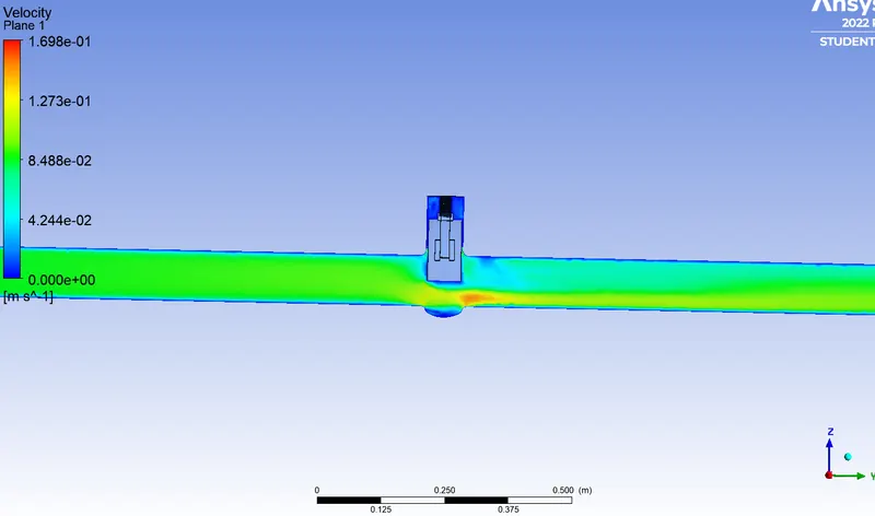
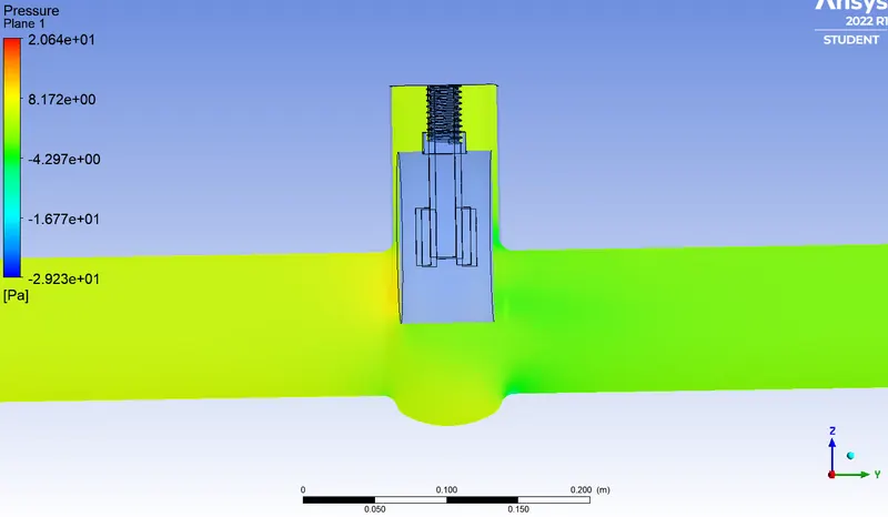
Mass flow rate = -0.65 kg/s = -10.3 gal/min
Outlet pressure = 3.5173 Pa = 0.0005101 psi
Flow coefficient = 335.96
Flow factor = 290.60
For 70mm lift
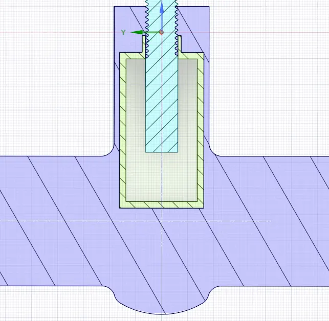
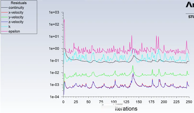
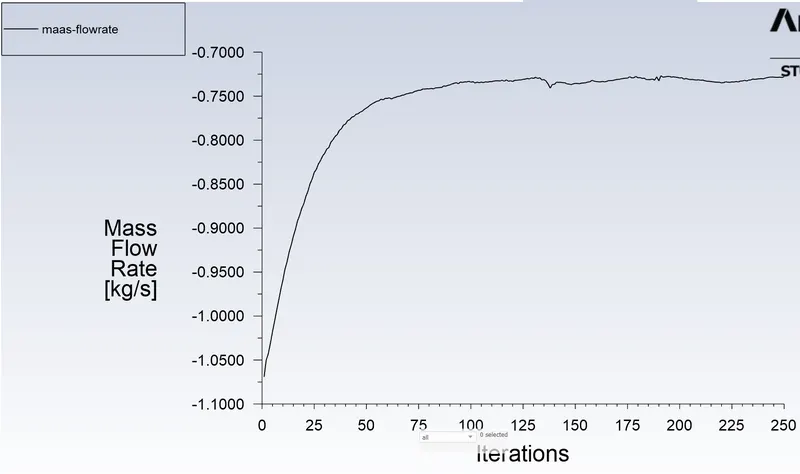
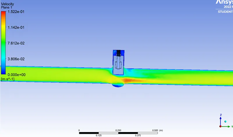
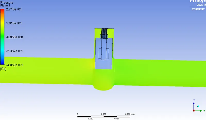
Mass flow rate = -0.7279 kg/s = -11.54 gal/min
Outlet pressure = 4.452 Pa = 0.0006457 psi
Flow cofficient = 406.90
Flow factor = 351.96
|
Lift (mm) |
Mass Flow Rate (gal/min) |
Flow Coefficient | Flow Factor |
| 10 | -2.35 | 68.12 | 58.92 |
| 20 | -3.76 | 101.14 | 87.48 |
| 30 | -5.17 | 143.83 | 124.40 |
| 40 | -7.48 | 217.63 | 188.24 |
| 50 | -9.12 | 281.12 | 243.16 |
| 60 | -10.30 | 335.96 | 290.60 |
| 70 | -11.54 | 406.90 | 351.96 |
Conclusions
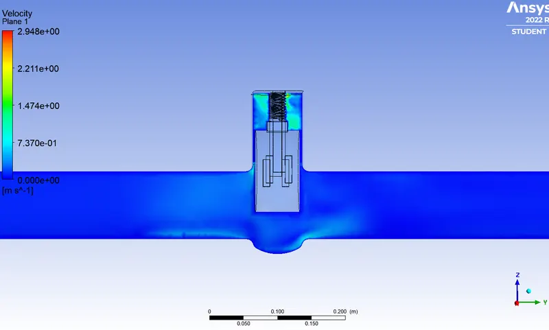
The increase in the rise of gate disc is the main reason for varying velocity and pressure contour plots in the region.The flow coefficient and flow factor determine the selection of gate valve.
Increase in valve lift increases the mass flow rate, Similarly,it also leads to an increase in flow factor and flow coefficient .Hemce , we can conclude that valve lift has a direct impact on flow factor and mass flow rate.
Thus,parametric study helps to analyse different positions of valve opening and gives the benifit to get easy and quick results.