Week 9 - Parametric study on Gate valve.
1. Introduction
Gate valves (also termed as Sluice Valve) is used to regulate the fluid flow passing through it by lifting and lowering the Valve Gate or the barrier. It generally requires very less space and the flow rate interruption can be found negligible when the Valve gate is fully opened.
2. Problem Statement
- For this challenge, you will have to perform a parametric study on the gate valve simulation by setting the opening from 10 % to 80%.
- Obtain the mass flow rates at the outlet for each design point.
- Calculate the flow coefficient and flow factor for each opening and plot the graph.
- Discuss the results of the mass flow rate and flow coefficient.
3. Problem Setup for Simulation
3.1 Geometry Setup
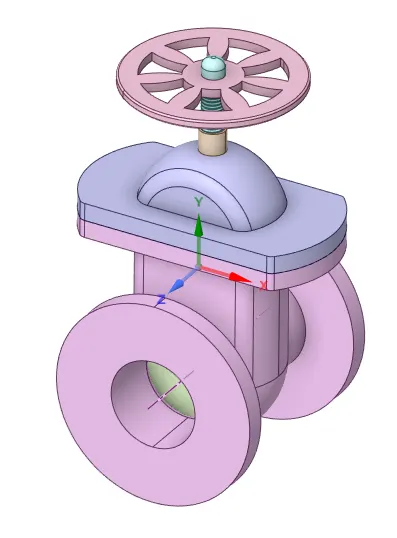
- The Geometric model is received into SpaceClaim for which the volume extraction is performed and the main geometry is suppressed to get the volume into the Mesher.
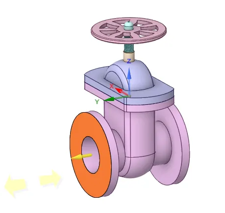
- With the help of the Pull Tool, the inlet and the outlet need to be pulled for 800 mm by selecting the highlighted surface in-order to create Volume for simulating the flow.
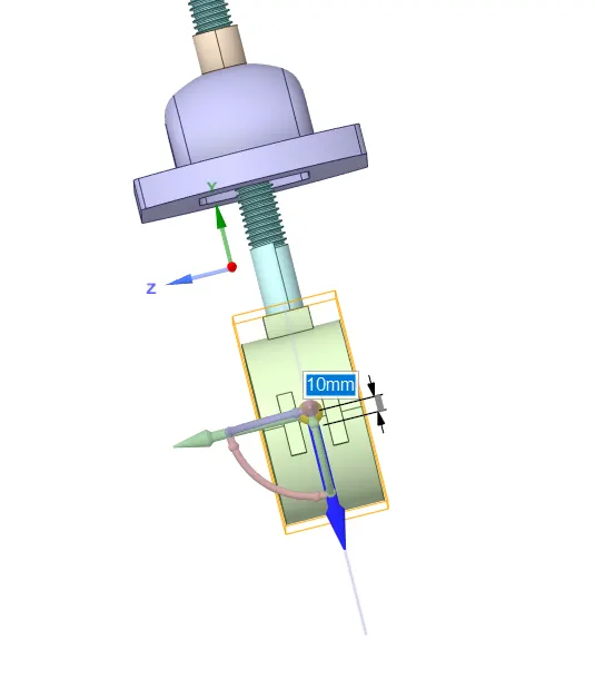
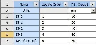
- The parameters have to be set to increase the valve disc to be lifted with certain heights which has to be mentioned in the parameters section after creating them.

- After this all the bodies are unhide to select the edges to create a volume which is used in simulating the flow in it.
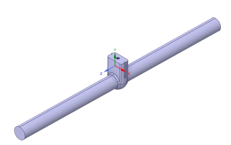
- Following are the remaining Parameter setup representations
- For 0 mm
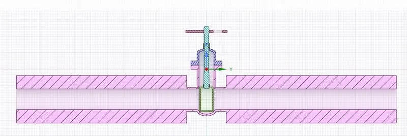
- For 10 mm
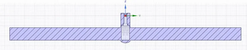
- For 20 mm
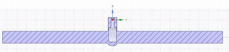
- For 40 mm
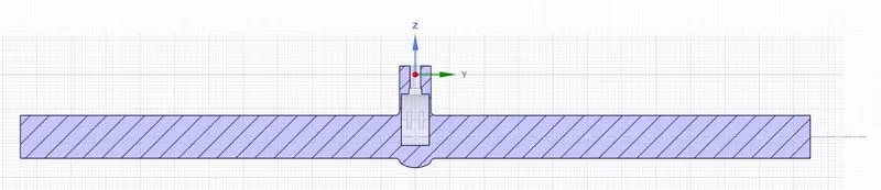
- For 60 mm
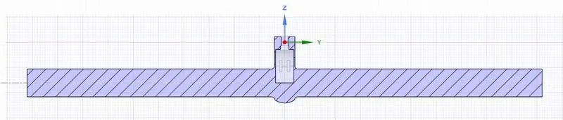
- For 80 mm
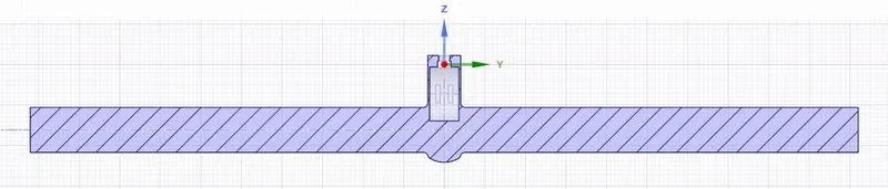
3.2 Mesh Setup
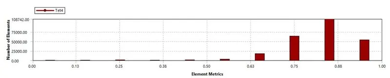
- The meshing has been performed on this with an element size considered for 40 mm which is as represented below along with the Mesh Element Quality Metric.
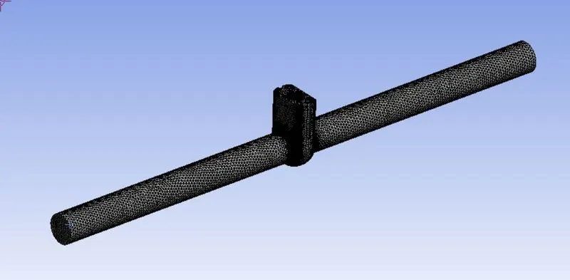
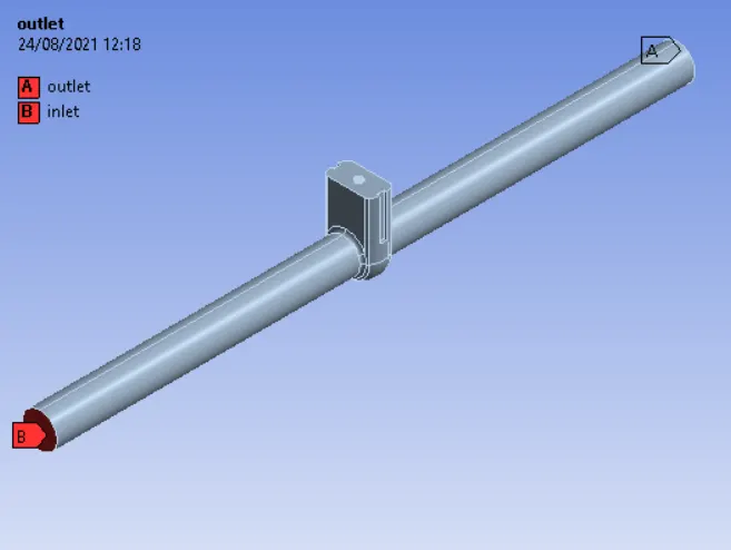
- The Named Sections are given accordingly.
3.3 Solver Setup
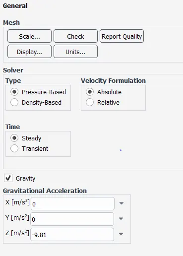
- For Steady State simulation, Steady is selected in the Time Section of the General Tab is to be selected. With gravity being assigned as below.
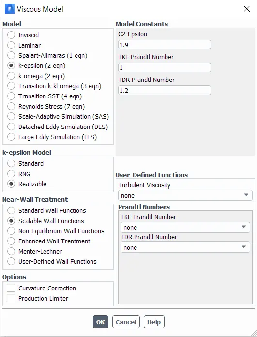
- “K-Epsilon” is used in the Viscous Tab. With all the default selections used as represented below.
- Setting up material, since usage of water is very much necessary than using any other fluid, Water liquid (h2o) is copied from Fluent Database and is assigned to the Volume from Cell Zones.
- The inlet boundary condition is changed to “Pressure Inlet” and is considered to be 10 Pa for all the cases.
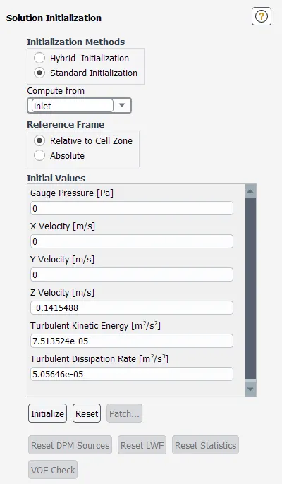
- Standard Solution method is employed with selecting “Compute From” tab to “Inlet” as the flow is computed from inlet with reference Frame to be Relative to Cell Zone which helps ANSYS to calculate rest of the required values.
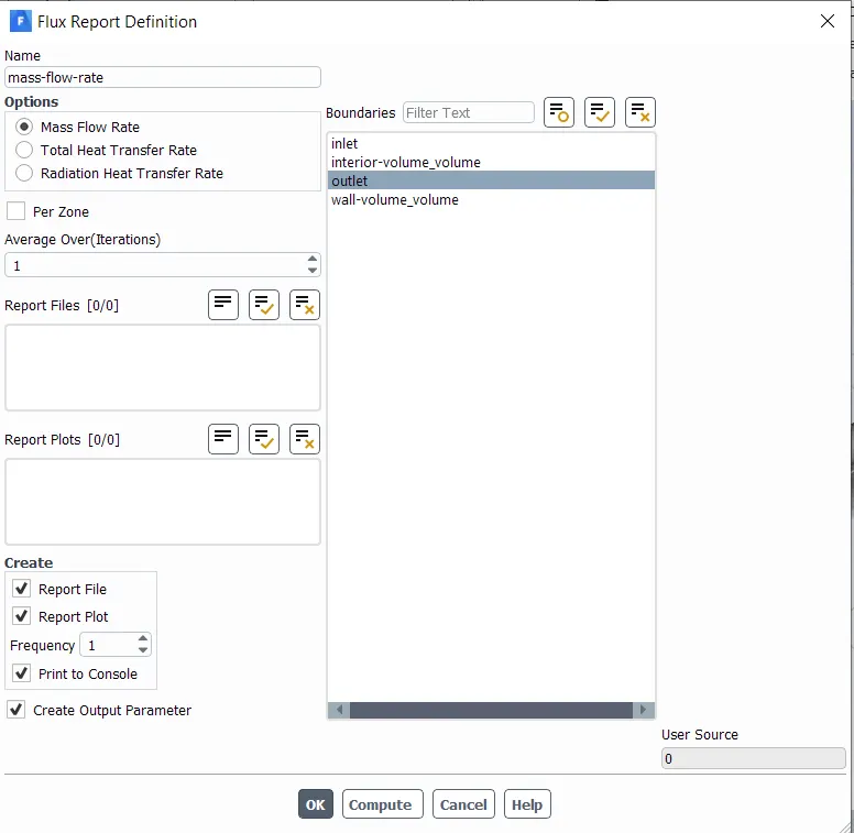
- The Definitions are setup to get the Mass Flow Rate Plot for the Outlet and the option of “Create Output Parameter” is selected to get the mass flow rate values at the parameters section.
- After Initializing, required velocity and pressure contours are created.
- Number of Iterations is set to 300 and the calculation is run.
4. Simulation Results
4.1 Parameter – 1: 10mm
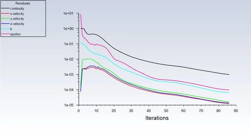
- Residual Scaled Graph for 10 mm
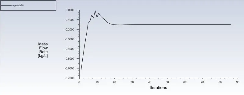
- Mass Flow Rate for 10 mm
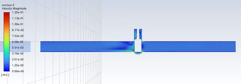
- Velocity Contour for 10 mm
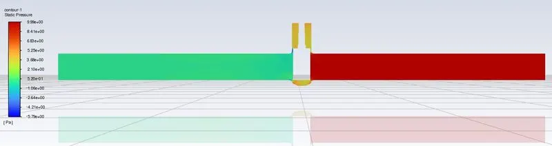
- Pressure Contour for 10 mm
4.2 Parameter – 2: 20mm
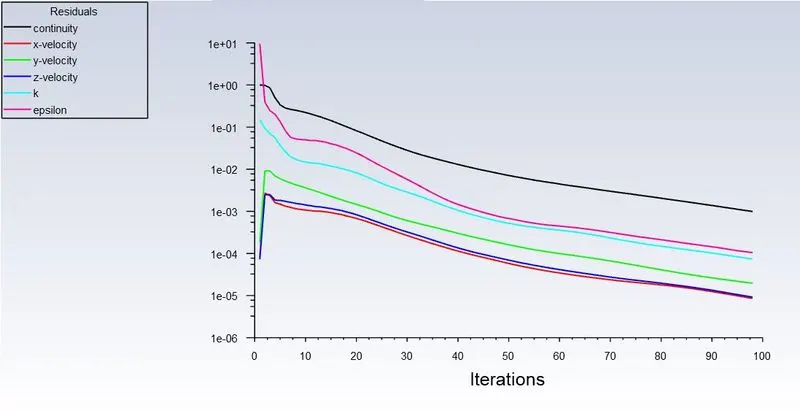
- Residual Scaled Graph for 20 mm
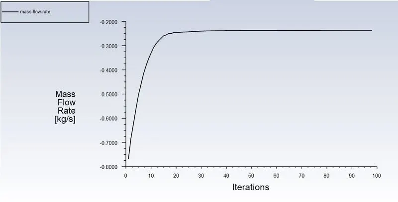
- Mass Flow Rate for 20 mm
- Velocity Contour for 20 mm
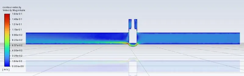
- Pressure Contour for 20 mm
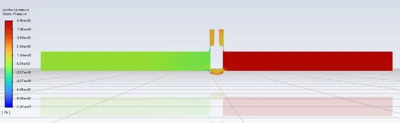
4.3 Parameter – 3: 40mm
- Residual Scaled Graph for 40 mm
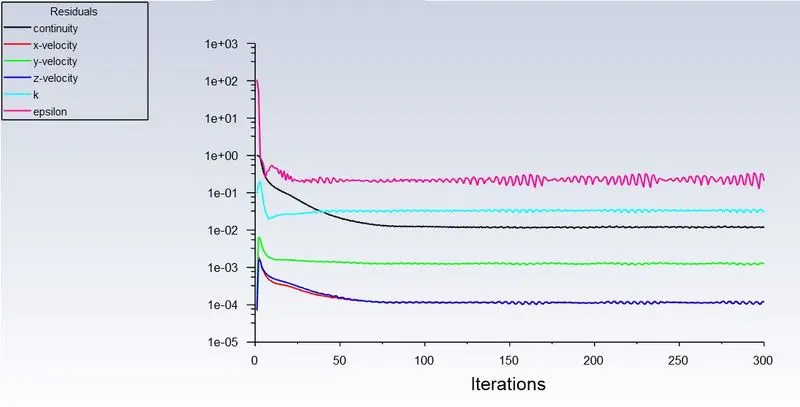
- Mass Flow Rate for 40 mm
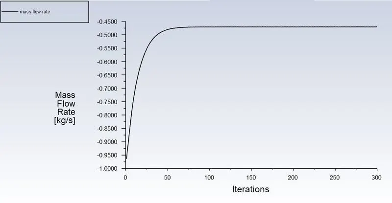
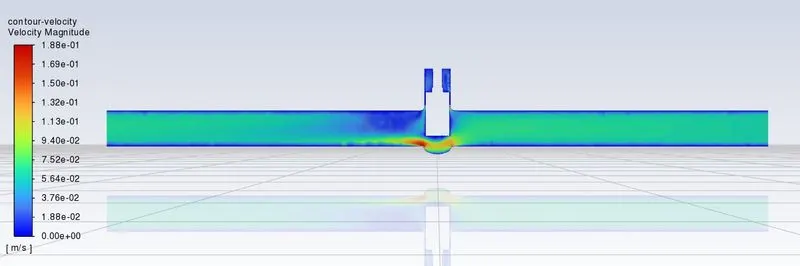
- Velocity Contour for 40 mm
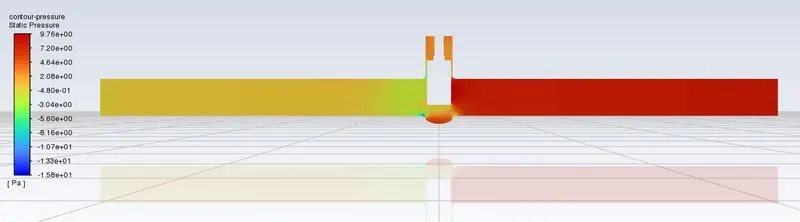
- Pressure Contour for 40 mm
4.4 Parameter – 4: 60mm
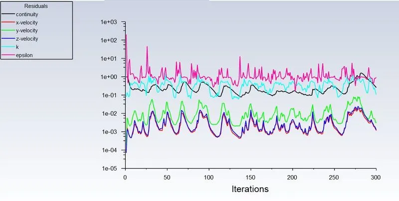
- Residual Scaled Graph for 60 mm
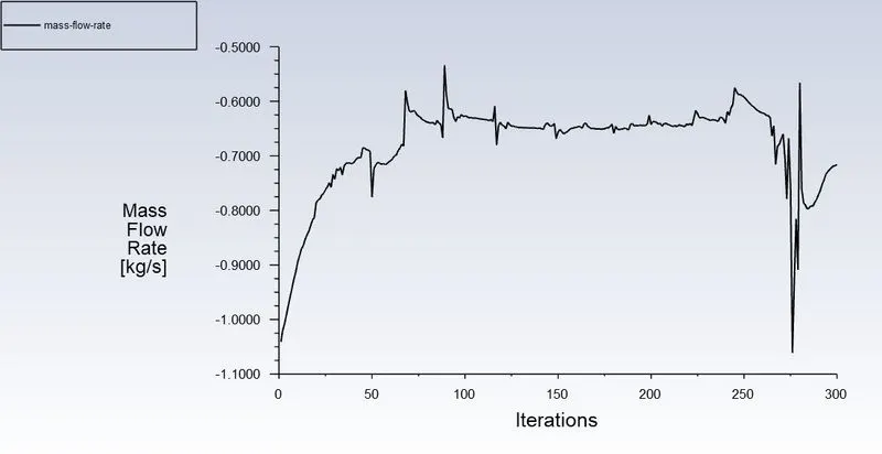
- Mass Flow Rate for 60 mm
- Velocity Contour for 60 mm
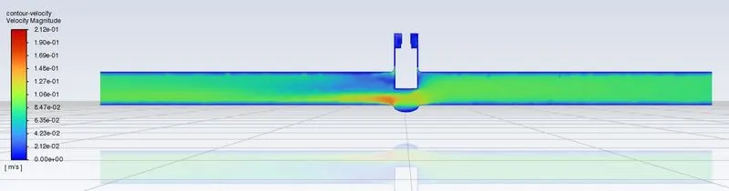
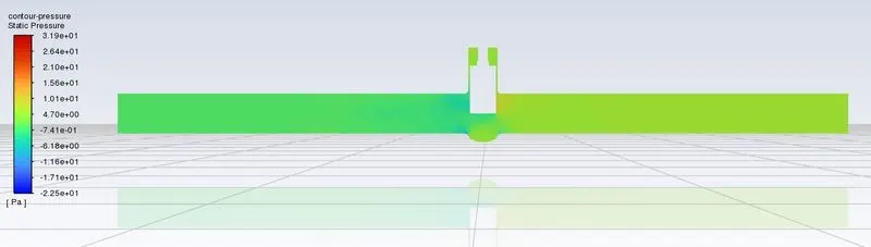
- Pressure Contour for 60 mm
4.5 Parameter – 5: 80mm
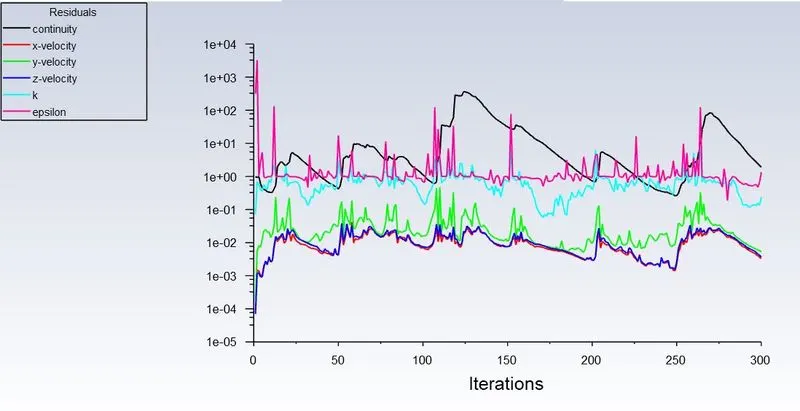
- Residual Scaled Graph for 80 mm
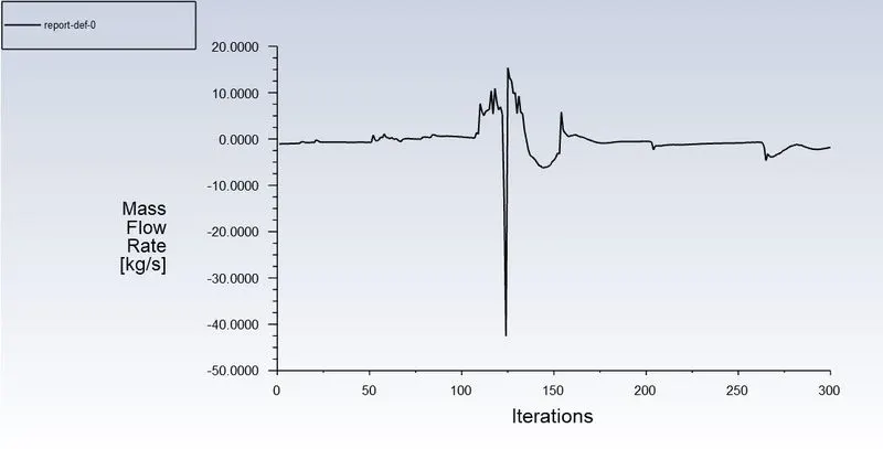
- Mass Flow Rate for 80 mm
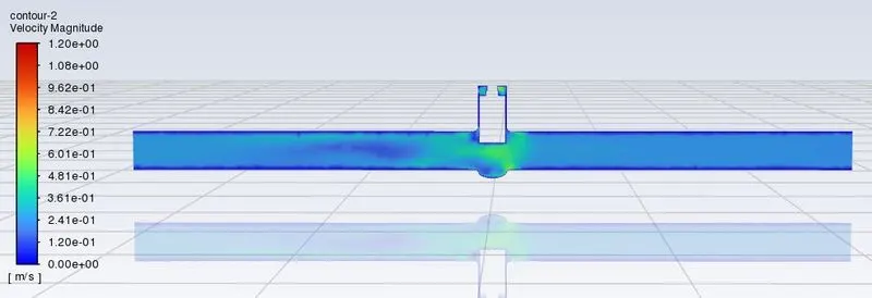
- Velocity Contour for 80 mm
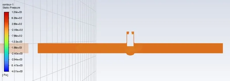
- Pressure Contour for 80 mm
5. Discussion of Results and Conclusion
The main aim of this challenge is to understand the mass flow rate and it's respective flow coefficient when there is a variation in the valve opening. For such reason a parametric study of the valve opening distances considered to be both adjecent and an alternating value to understand gradual increase and higher increase in valve values. The effectiveness of the gate valve in allowing the flow relative to the opening is measured by its coefficient. The relationship between the inlet and the outlet pressure drop of a gate valve and their associated rate of flow is known as the flow coefficient.
To calculate the Flow Coefficient for the given parameters, It can be represented mathematically as,
`C_v=Q.√(S/(∆P))`
In this,
Q = Flow Rate (gpm)
S = Specific Gravity of the Fluid
△P = Pressure Drop (psi)
In here Flow rate in Gallons per minute is converted from Kg/s as,
1 Kg/s = 15.85 gpm
And the equation to calculate Flow Factor of the fluid is represented as,
In this,
Kv = Flow Factor
Cv = Flow Coefficient
Following table shows the mass flow rate values from the simulations in Kg/s.
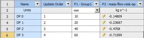

From the above tables and equations, the -ve sign indicates that the flow is moving in the -ve Y-Axis as the inlet-outlet are setup and the Flow Coefficient and the Flow Factor can be calculated and has been represented in the tabular form below.
|
S. No. |
Disc Lift (mm) |
Mass Flow Rate |
Flow Coefficient |
Flow Factor |
|
1 |
10 |
0.14809 |
0.74228 |
0.64207 |
|
2 |
20 |
0.23687 |
1.18727 |
1.02698 |
|
3 |
40 |
0.4708 |
2.35978 |
2.04120 |
|
4 |
60 |
0.71599 |
3.58877 |
3.10428 |
|
5 |
80 |
1.8277 |
9.16099 |
7.92425 |
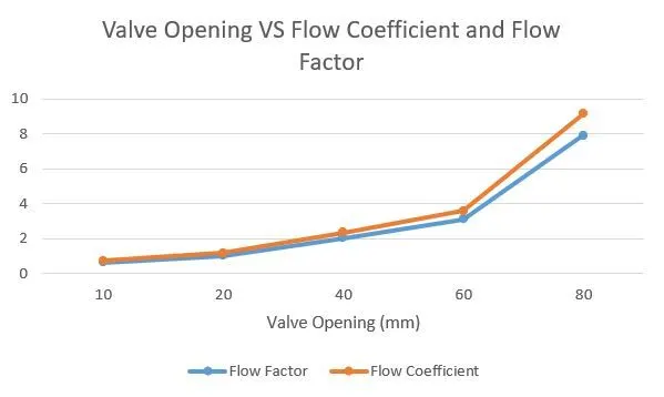
From the above simulations, As the valve opening is increased, the mass flow rate, flow coefficient and flow factor are also observed to be increasing. It can be derived that the valve opening is directly proportional to the mass flow rate and other factors.
From the Graph, it contrasts the flow factor and coefficient with valve opening. It is obvious that the two quantities grow with the size of the opening but Flow coefficient is observed to be higher than the Flow Factor in the last case for maximum valve opening compared to the other valve opening parameters with a gradual increment in the flow coefficient values.