Week 10 - Simulating Combustion of Natural Gas.
1. Introduction
Combustion is the process which involves the burning of fuel in a combustion chamber with the characteristics to be observed being turbulence of the Fluid, Its flow rate, chemical reactions and heat transfer characteristics. These characteristics are calculated by their respective governing equations along with other necessary physical and chemical processes which hs to be considered.
Some of these processes can be briefed as below:
1.1 Chemical Kinetics:
Kinetics of a reaction is another name for it. The area of physical chemistry known as chemical kinetics is dedicated to studying the speeds of chemical reactions. Additionally, it contrasts with thermodynamics, which only addresses the direction of a process and says nothing about its rate. Chemical kinetics is the study of how experimental conditions affect a chemical reaction's rate of progression and reveal details about the mechanism and transition states. Also, to the development of mathematical models that can also convey the features of a chemical reaction.
1.2 Chemical Reaction Model:
Through the application of these models, physical knowledge is converted into a mathematical formulation that can be applied to the computer simulation of real-world chemical engineering issues. The versatility of studying chemical processes under various circumstances is made possible by computer simulation. For each species involved in the reaction, conservation equations, diffusion terms, and reaction source terms must be solved.
1.3 Eddy - Dissipation Model:
The reaction mechanism for this simulation will be the Eddy - Dissipation model. It is a model for turbulent chemical reactions. The majority of combustibles burn quickly, and turbulence blending regulates the reaction's overall pace of activity.
While in non-premixed flames, turbulence slowly combines the fuel & oxidizer into the reaction zones where they ignition takes place swiftly, in premixed combustion, cold reagents and hot reagents are gradually blended further into reaction zones where the reaction proceeds promptly. The combustion in the premixed flames is presumed to be mixing-limited, and the intricate and frequently unknowable chemical dynamics can be safely disregarded.
These can also be categorised based on type of fuel and how it is used:
- Gaseous Fuel Combustion
- Liquid Fuel Combustion
- Solid Fuel Combustion
- Fuel Spray Combustion
- Pulverized Fuel Combustion
2. Problem Statement
-
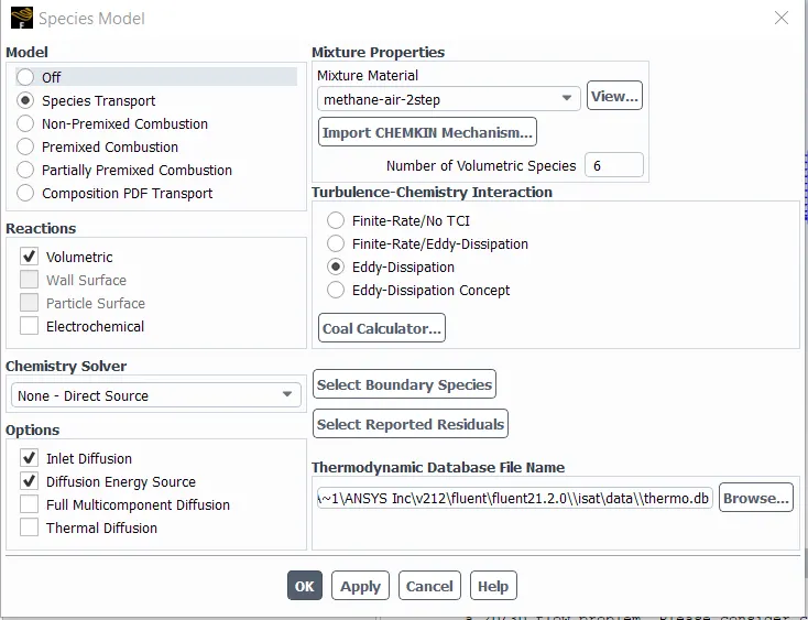
Use methane-air-2step as a mixture material than methane-air. [It allows to add water in the fuel or air].
-
Use a one-step soot model to calculate the soot formation.
3. Problem Setup for Simulation
3.1 Geometry Setup
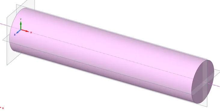
- The Geometric model is received into SpaceClaim for which the datum planes are to be created in-order to split them equally as represented below.
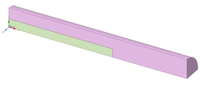
- Now the geometry is to be split twice using Y and Z planes. After splitting, only the first quarter geometry is to be saved and suppressing the remaining geometry as represented below.
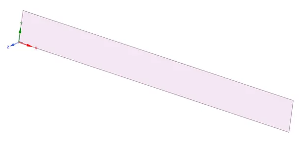
- The faces are to be copied into a new domain as a surface and is merged using Share tool to get the whole geometry as a single component
3.2 Mesh Setup
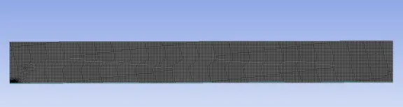
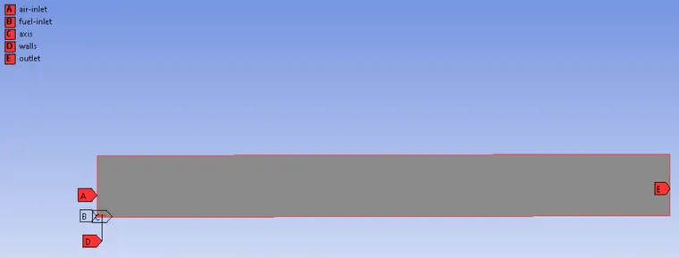
- The meshing has been performed on this with an element size considered for 2 mm which is as represented below.
- The Named Sections are given accordingly.
3.3 Solver Setup
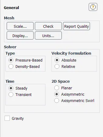
- For Steady State simulation, Steady is selected in the Time Section of the General Tab is to be selected. With Axisymmetric being assigned in 2D Space as below.
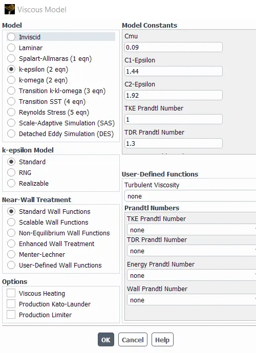
- “K-Epsilon” is used in the Viscous Tab. With all the default selections used as represented below. And also the Energy Equation is Turned On.
- Setting up material, since usage of water is very much necessary than using any other fluid, Water liquid (h2o) is copied from Fluent Database and is assigned to the Volume from Cell Zones.
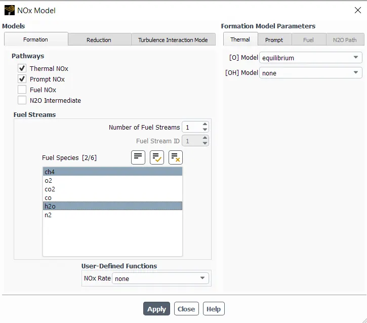
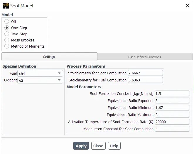
- The inlet boundary condition is changed to “Pressure Inlet” and is considered to be 10 Pa for all the cases.
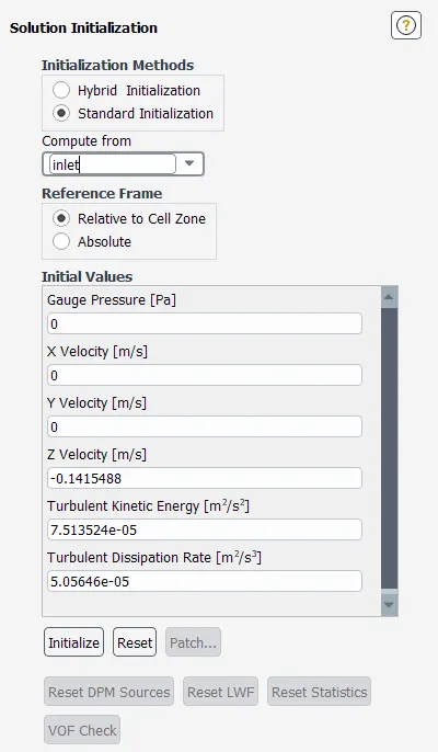
- Standard Solution method is employed with selecting “Compute From” tab to “Inlet” as the flow is computed from inlet with reference Frame to be Relative to Cell Zone which helps ANSYS to calculate rest of the required values.
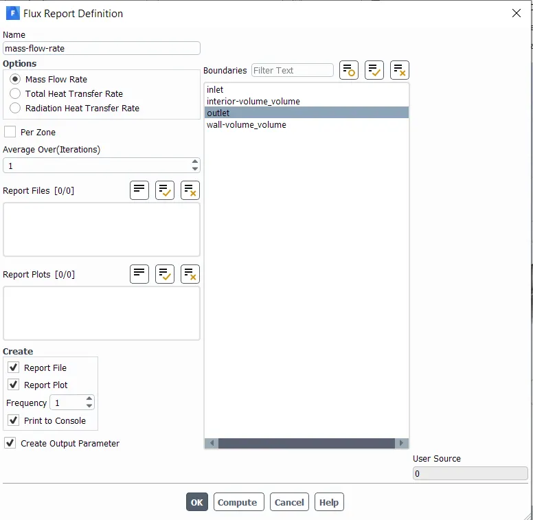
- The Definitions are setup to get the Mass Flow Rate Plot for the Outlet and the option of “Create Output Parameter” is selected to get the mass flow rate values at the parameters section.
- After Initializing, required velocity and pressure contours are created.
- Number of Iterations is set to 300 and the calculation is run.
4. Simulation Results
4.1 Part – 1
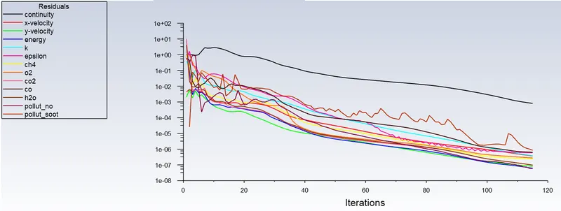
- Residual Scaled Graph
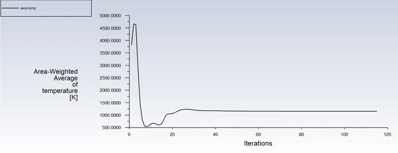
- Area Weighted Average Temperature
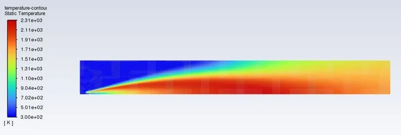
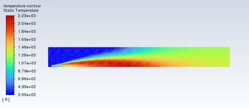
- Combustion Temperature Contour
4.2 Part – 2
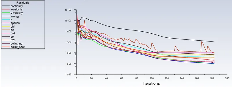
4.2.1 Ratio 9 Parts CH4 and 1 Part H2O
- Residual Scaled Graph
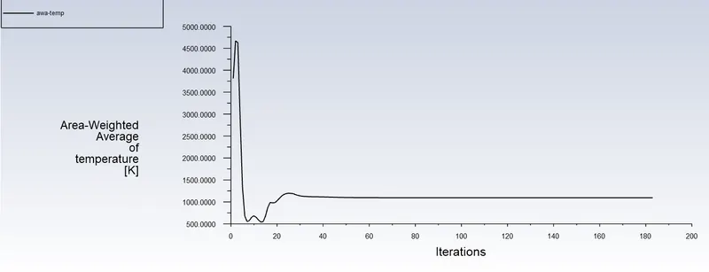
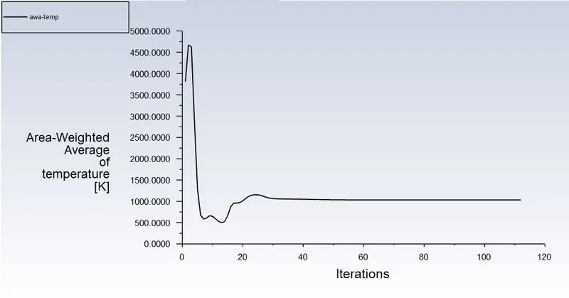
- Area Weighted Average Temperature
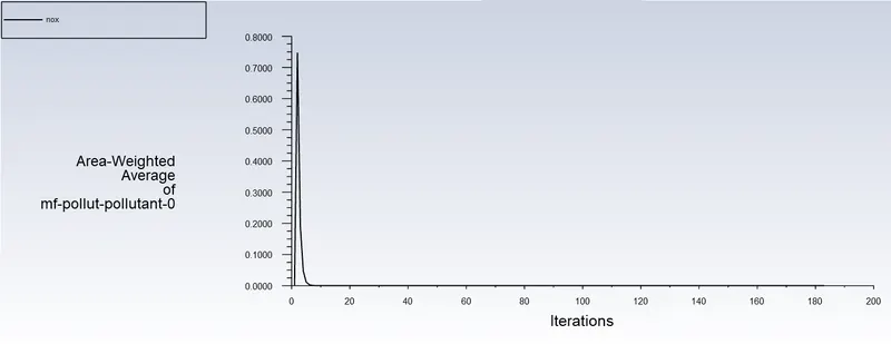
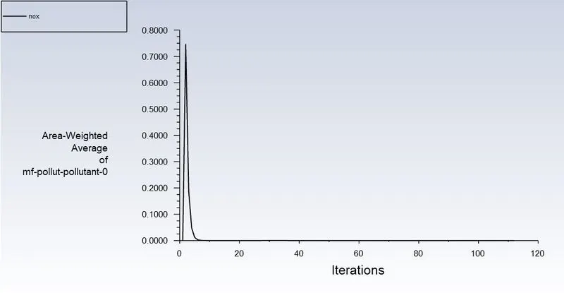
- Area Weighted Average NOx
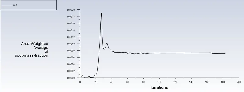
- Area Weighted Average Soot
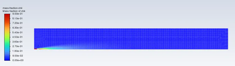
- CH4
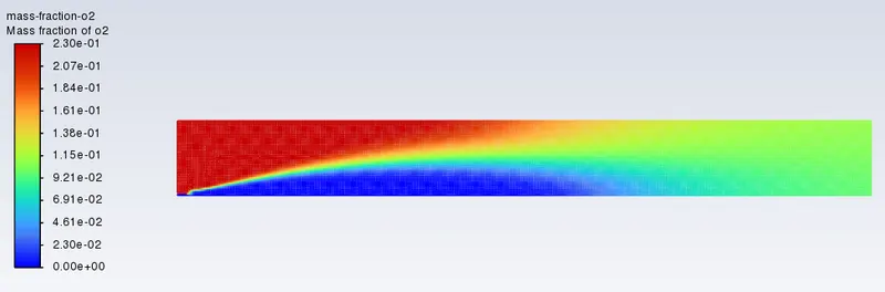
- O2
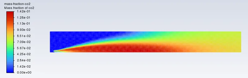
- CO2
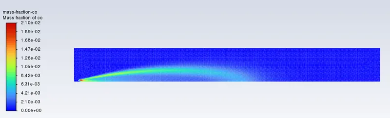
- CO
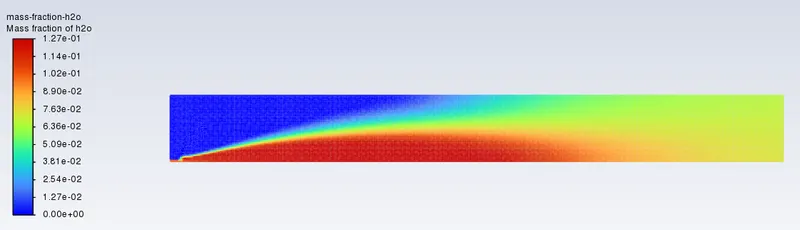
- H2O
- Combustion Temperature Contour
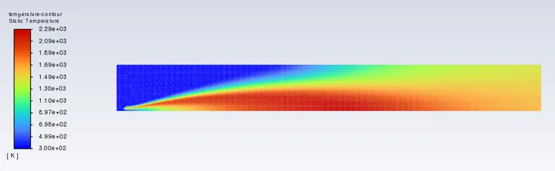
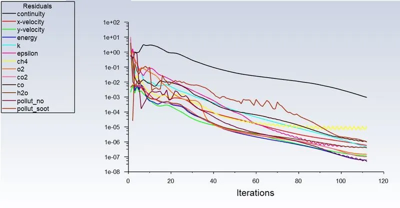
4.2.2 Ratio 8 Parts CH4 and 2 Parts H2O
- Residual Scaled Graph
- Area Weighted Average Temperature
- Area Weighted Average NOx
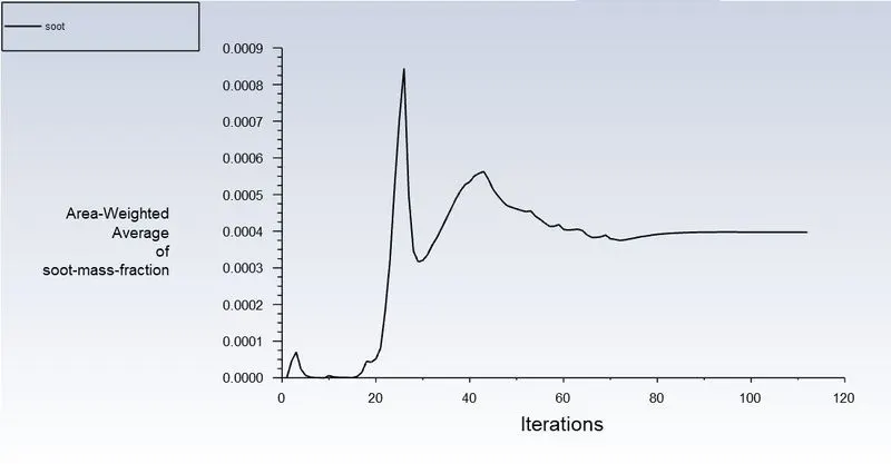
- Area Weighted Average Soot
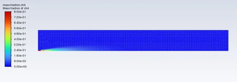
- CH4
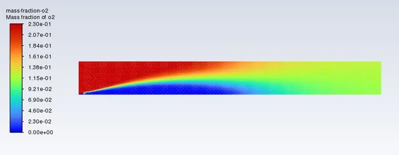
- O2
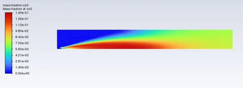
- CO2
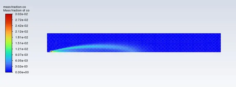
- CO
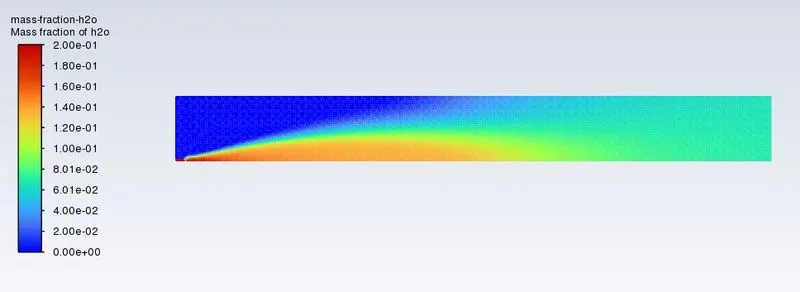
- H2O
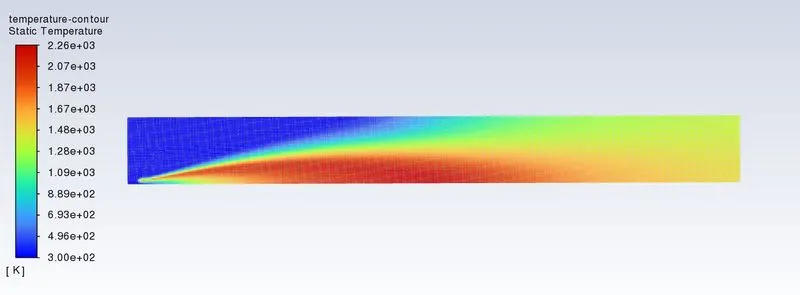
- Temperature Mix Contour
4.2.3 Ratio 7 Parts CH4 and 3 Parts H2O
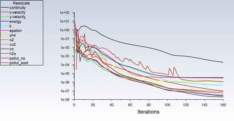
- Residual Scaled Graph
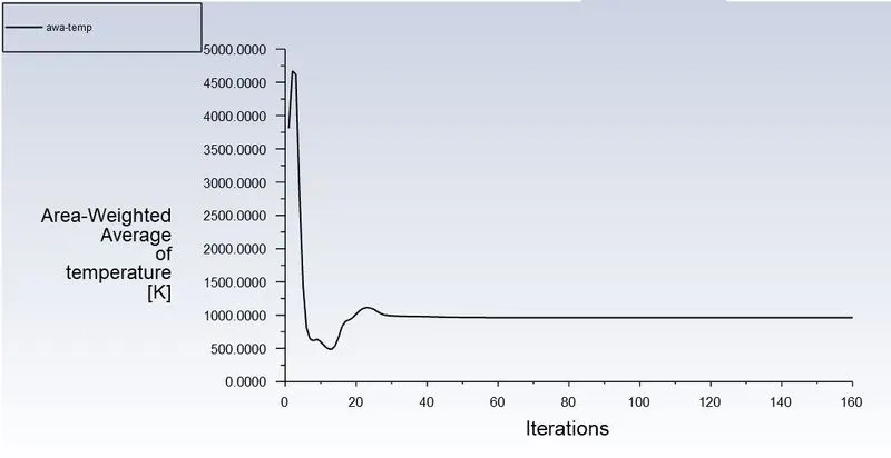
- Area Weighted Average Temperature
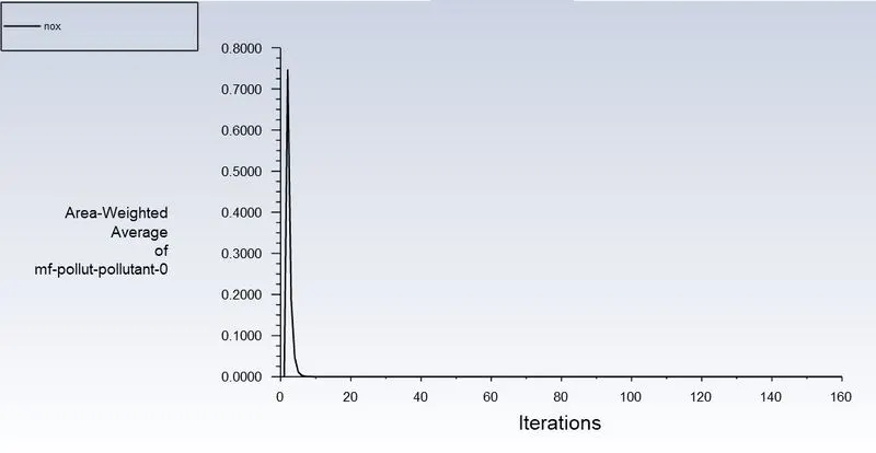
- Area Weighted Average NOx
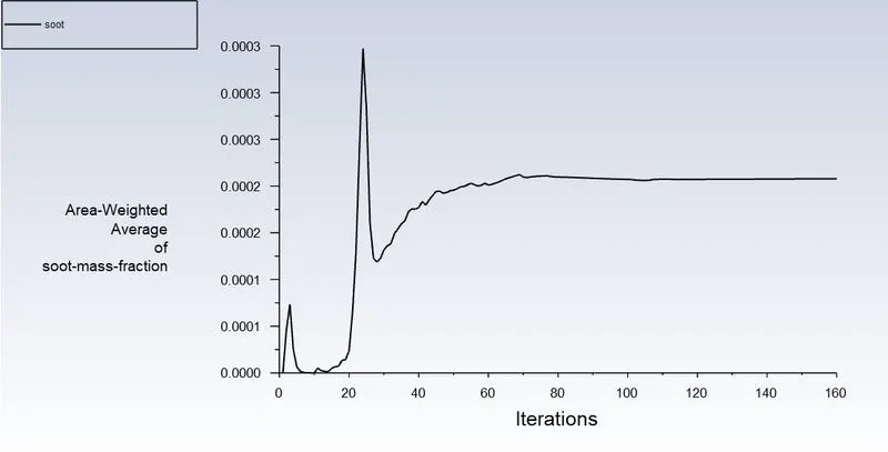
- Area Weighted Average Soot
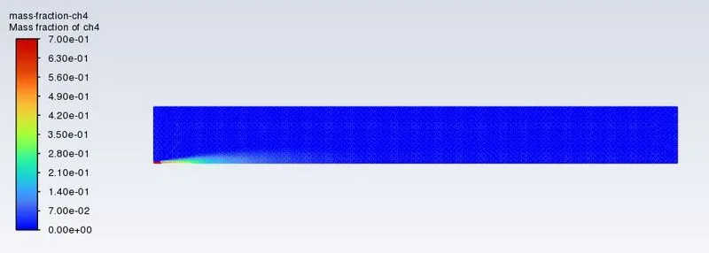
- CH4
- O2
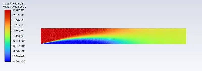
- CO2
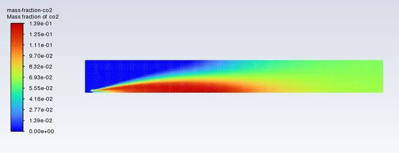
- CO
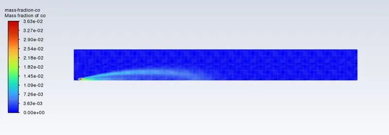
- H2O
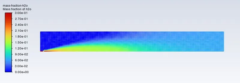
- Temperature Mix Contour
5. Discussion of Results and Conclusion
The formation of NOx and Soot in a combustion chamber has a harmful impact on the ecosystem. From the Problem Statement, it has to be found out that soot and NOx formation in occurs in combustion chamber. From the above simulation, it can be identified that, the formation of Soot and NOx takes place at the outlet of the geometry. As per the norm’s setup by the government, it is necessary to look for the least formation of these factors and to satisfy those requirements, the effect of adding the water in the fuel has been setup for simulation to check the reduction in the formation of these factors.
As per the Problem statement, the addition of water content in the fuel has been checked ranging from 5% to 30% by mole and these results has been extracted.
With the increase in the percentage of water, the pollutants NOx and soot are observed to be reducing from the above simulation results. This can be observed from the graph below based on the above table.
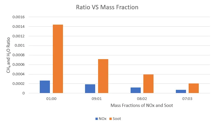
From the bove graph of Mass Fraction of NOx and Soot, there is a decrement observed with the increment in the Water (H2O) percentage in the mixture. But it can also be observed that the decrement in NOx polutants in comprison with the decrement in Soot is found to be higher resulting in more reduction of NOx polutants with the addition of water (H2O) to the Combustion Mixture.
6. References
- Chybowski, L., Laskowski, R. and Gawdzińska, K., 2015. An overview of systems supplying water into the combustion chamber of diesel engines to decrease the amount of nitrogen oxides in exhaust gas. Journal of Marine Science and Technology, 20(3), pp.393-405.
- Mazzei, L., Puggelli, S., Bertini, D., Pampaloni, D. and Andreini, A., 2017. Modelling soot production and thermal radiation for turbulent diffusion flames. Energy Procedia, 126, pp.826-833.