Week 2 - Flow over a Cylinder.
1. Introduction
Researchers still find it extremely difficult to simulate flow across a cylinder. Understanding the intricate behaviours of fluid mechanics is greatly helped by this simulation. Applications include understanding the flow dynamics of residual flow behind the stationary cylinder and issues with mass & heat transmission. These further can be applied to understanding the Flow Dynamics of an airfoil. Apart from applications, the focus for this kind of flow simulation is on the phenomenon of Vortex Shedding and Kamran Vortex Street which have been discussed below. And for these types of problems, the calculation of Strouhal Number is of significance.
1.1 Vortex Shedding:
It is a phenomenon when the flow crosses the bluff body, vortices are shed alternately from one side to the other, & where alternating low-pressure zones are generated to the downside of the bluff body giving rise to a fluctuating force acting at right angles to the flow direction.
1.2 Von Kamran Vortex Street:
The vortices which are shedder alternately from either side of the bluff body & it creates the pattern of swirling vortices. These patterns of swirling vortices are repeated periodically & it is called as von Kamran vortex street.
Depends on the force, the body might move towards the direction of the force. If the bluff body doesn’t mount rigidly on the structure than it will start vibrating with harmonic oscillations driven by the energy of the flow & if the vortex shedding frequency of the vibration reaches the frequency of the structural-vibration frequency of the body than the body start resonating. This phenomenon is of major importance in engineering design because the alternate formation and shedding of vortices also creates alternating forces, which occur more frequently as the velocity of the flow increases.
When the frequency is in the audible range, a sound can be heard and the body appears to sing. Many structures failed because of this phenomenon. Because of this effect, it is very important to study the vortex shedding to make sure performance of the components will not affect by the vortex shedding. The Strouhal number has been used while studying this type of phenomena.
1.3 Strouhal Number (Sr or St):
This is a dimensionless number which used to a measure of the vortex shedding frequency. This number is function of Reynolds number but less of surface roughness & freestream turbulence.
2. Problem Statement
The problem is about simulating the flow over a cylinder for both Steady State and Unsteady State conditions by varying the Reynolds Number (Re) as mentioned below to understand the Vortex Shedding effects in the flow. This objective is needed to be achieved using Fluent Solver. The Flow simulation is to be performed for the Reynolds Numbers (Re) in the first part of the assignment with,
- Re = 10
- Re = 100
- Re = 1000
- Re = 10000
- Re = 100000
With First Part of the assignment being the usage of Steady and Unsteady State Simulation for Re = 100 also calculating the Strouhal Number and Steady State Solver is to be used for the Second Part of the Assignment
The below mentioned parameters for the simulation is the same for all the cases:
|
Density (Kg/ m3) |
Viscosity (N.s/m2) |
Length (m) |
|
|
Air |
1 |
0.02 |
2 |
3. Problem Setup for Simulation
3.1 Geometry Setup
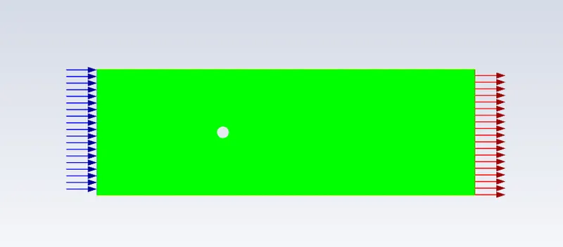
- The geometry is created in SpaceClaim where a rectangular section is created with a circular section cut out from the rectangular section as represented below.
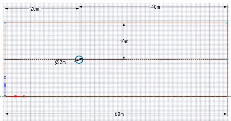
- Pull feature is to be used on the created geometry to make the drawing as a Surface as shown below.
3.2 Mesh Setup
- A Method Mesh is being used to obtain a mesh of Triangles considering an element size of 0.2 m and considering an Ede sizing of 36 Number of Divisions around the cylinder edge to obtain an even mesh used for creating an inflation of 5 Layers around the cylinder to obtain better flow results.
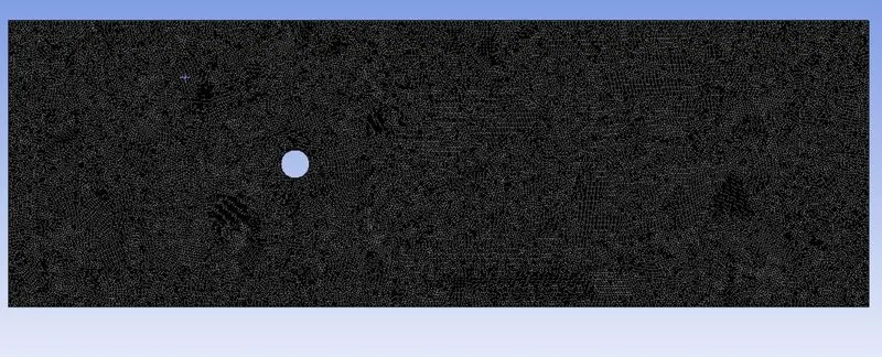
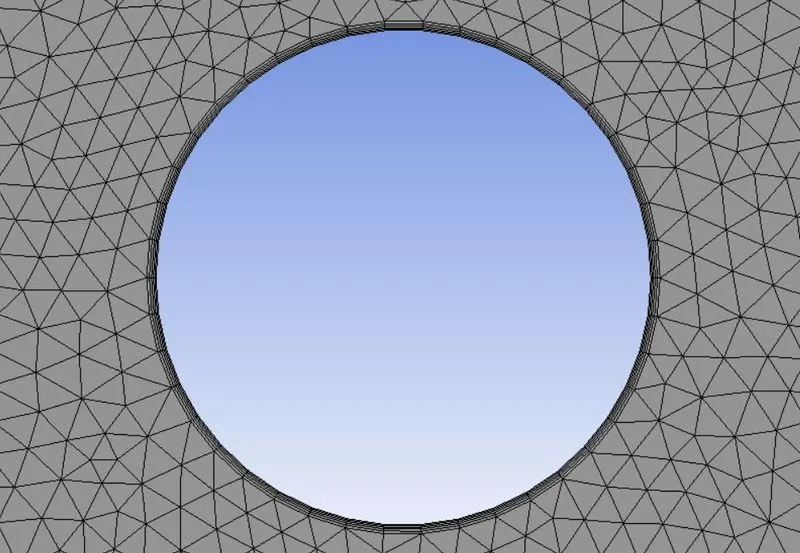
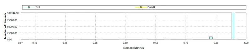
- The Mesh Quality is obtained above 5%.
- Named Sections are given accordingly
3.3 Solver Setup
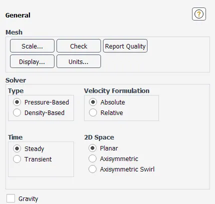
- For Steady State simulation, Steady is selected in the Time Section of the General Tab and Transient is selected for Unsteady State simulation.
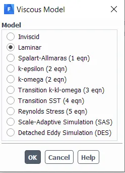
- For Both the scenarios, Laminar Flow is to be selected.
- The material properties are to be setup as per the Parameters mentioned in the above section for all the cases.
- The inlet velocity is to be calculated based on the given Reynolds Number using the below Formulae.
|
Reynolds Number |
Flow Velocity (m/s) |
|
10 |
0.1 |
|
100 |
1 |
|
1000 |
10 |
|
10000 |
100 |
|
100000 |
1000 |
- Setting up a Monitor Point at 10 m from the centre of the cylinder section in the same axis.
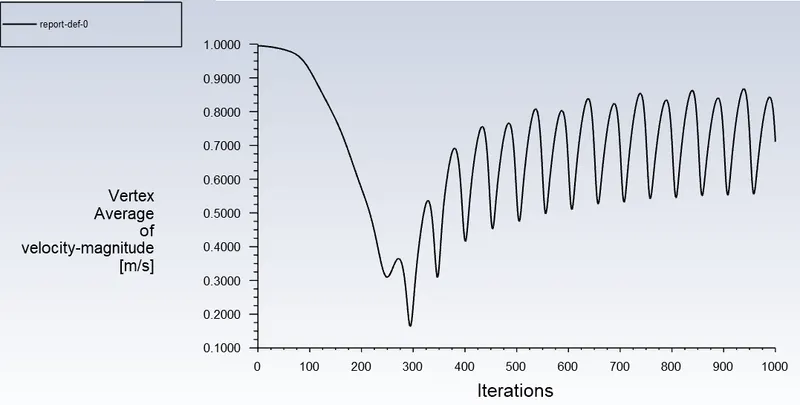
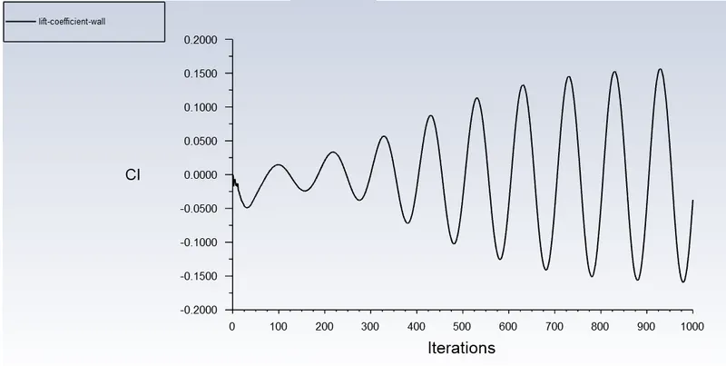
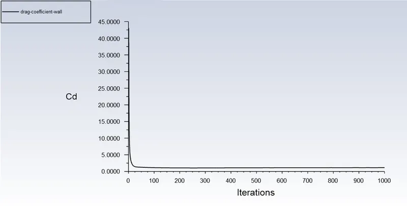
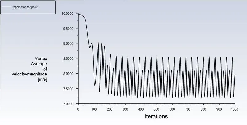
- The Surface reports are to be created using the Vertex Average set to the Monitor Point to get the Velocity Change results. Along with Vertex Average Report, Lift and Drag Coefficient Reports are to be generated for the Monitor Point.
- A SIMPLE Solution Method is employed.
- The Setup is Initialised, and the number of iterations is set to 1000 Iterations to obtain the required result.
4. Simulation Results
4.1 Re 100 – Steady
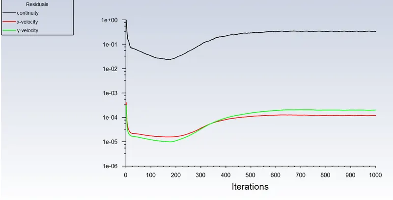
- Residual Scaled Graph for Re 100 – Steady
- Area Vertex Monitor Point for Re 100 – Steady
- Lift Coefficient for Re 100 – Steady
- Drag Coefficient for Re 100 – Steady
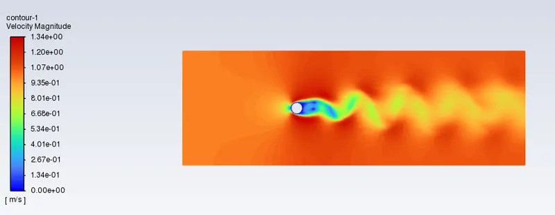
- Velocity Contour for Re 100 – Steady
Video Link: Re 100 - Steady - Pressure Contour for Re 100 – Steady
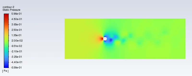
4.2 Re 100 – Transient
- Residual Scaled Graph for Re 100 – Transient
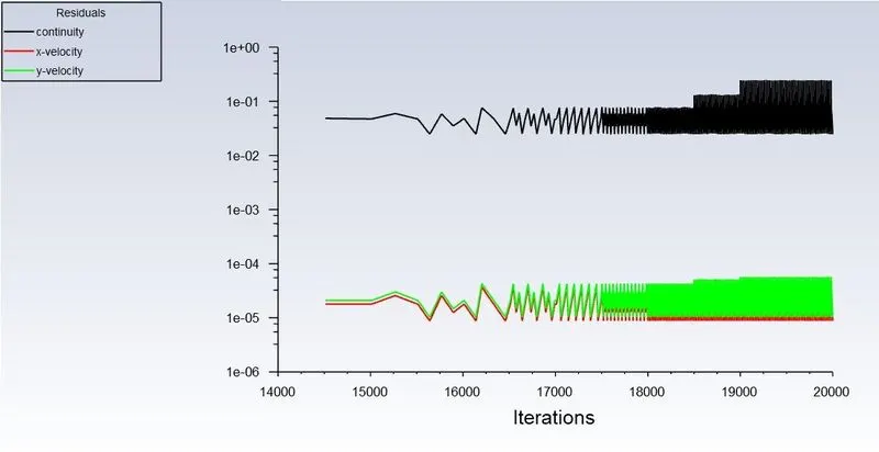
- Area Vertex Monitor Point for Re 100 – Transient
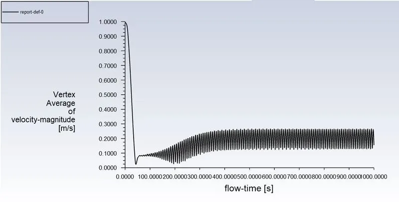
- Lift Coefficient for Re 100 – Transient
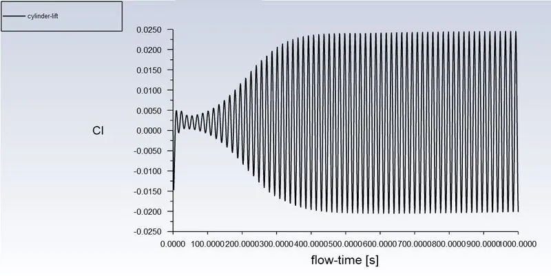
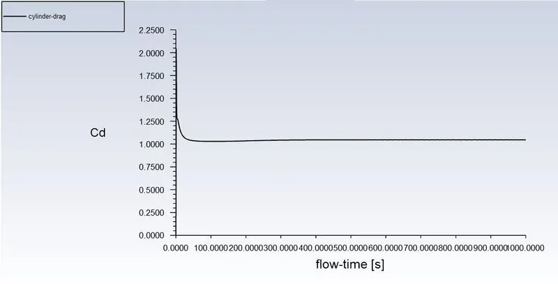
- Drag Coefficient for Re 100 – Transient
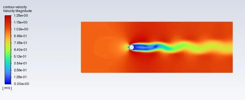
- Velocity Contour for Re 100 – Transient
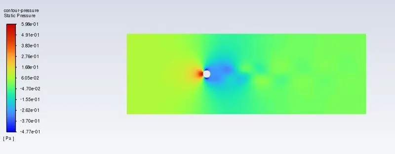
Video Link: Re 100 - Unsteady - Pressure Contour for Re 100 – Transient
4.3 Re 10 – Steady
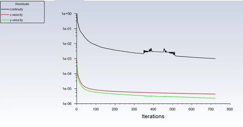
- Residual Scaled Graph for Re 10 – Steady
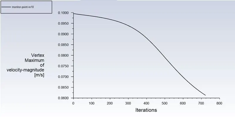
- Area Vertex Monitor Point for Re 10 – Steady
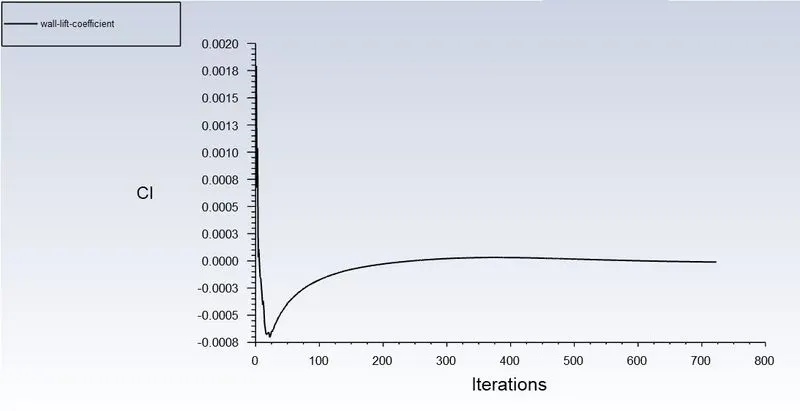
- Lift Coefficient for Re 10 – Steady
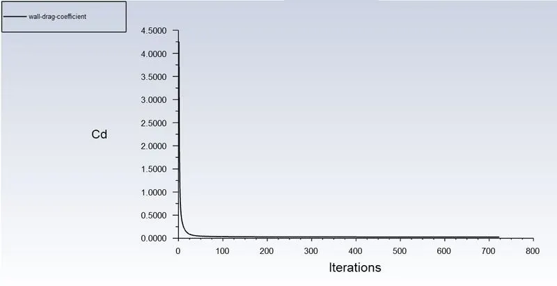
- Drag Coefficient for Re 10 – Steady
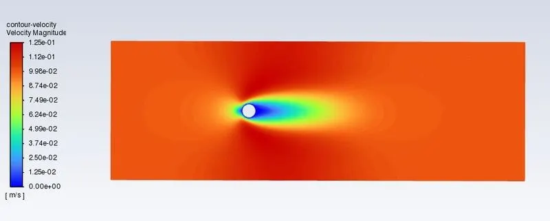
- Velocity Contour for Re 10 – Steady
Video Link: Re 10 - Steady
4.2 Re 1000 – Steady
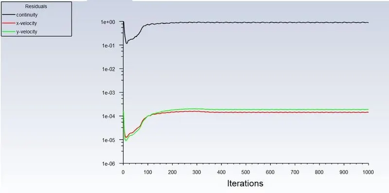
- Residual Scaled Graph for Re 1000 – Steady
- Area Vertex Monitor Point for Re 1000 – Steady
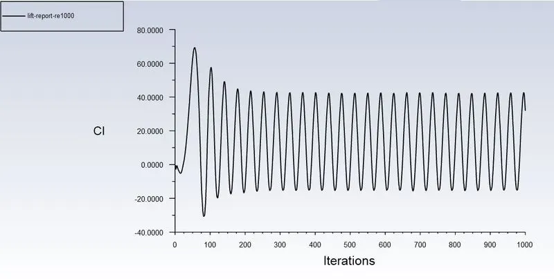
- Lift Coefficient for Re 1000 – Steady
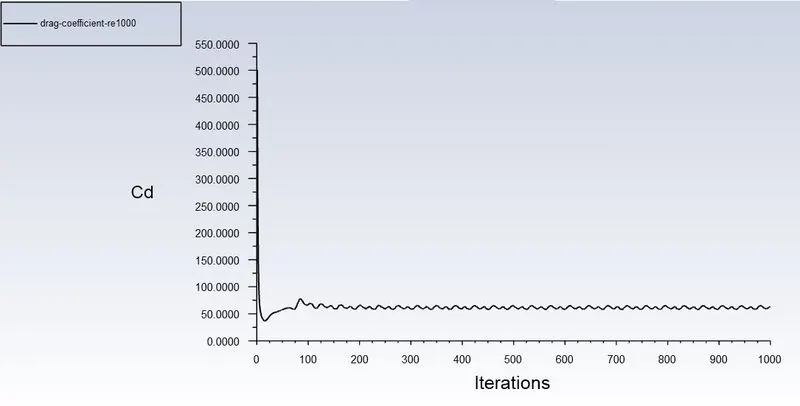
- Drag Coefficient for Re 1000 – Steady
- Velocity Contour for Re 1000 – Steady
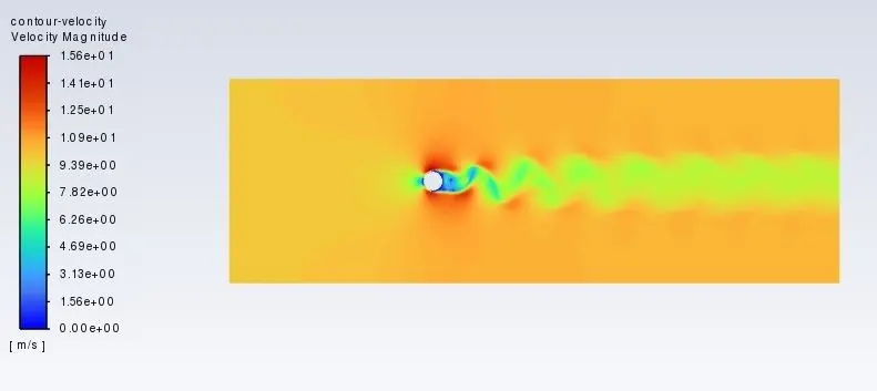
Video Link: Re 1000 - Steady
4.4 Re 10000 – Steady
- Residual Scaled Graph for Re 10000 – Steady
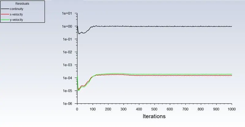
- Area Vertex Monitor Point for Re 10000 – Steady
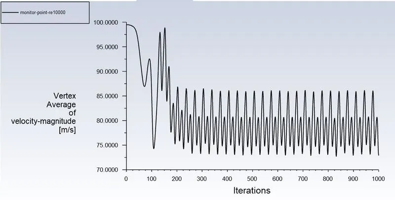
- Lift Coefficient for Re 10000 – Steady
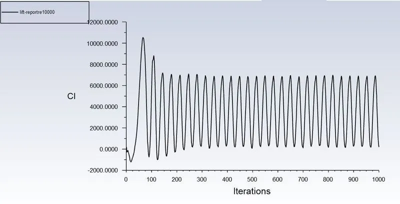
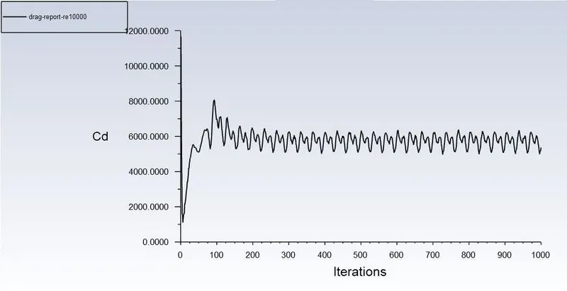
- Drag Coefficient for Re 10000 – Steady
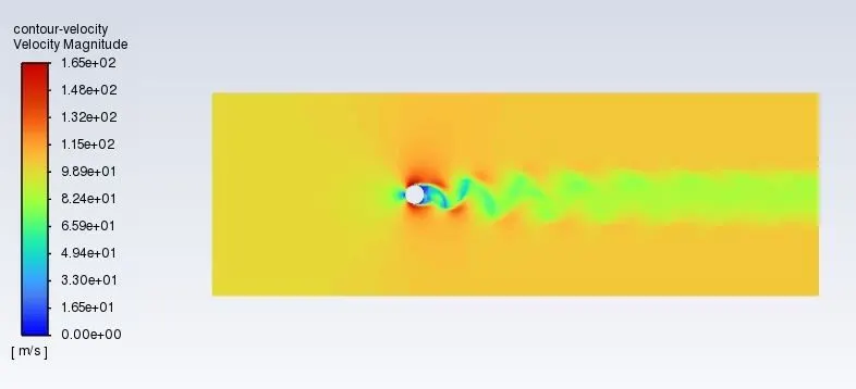
- Velocity Contour for Re 10000 – Steady
Video Link: Re 10000 - Steady
4.2 Re 100000 – Steady
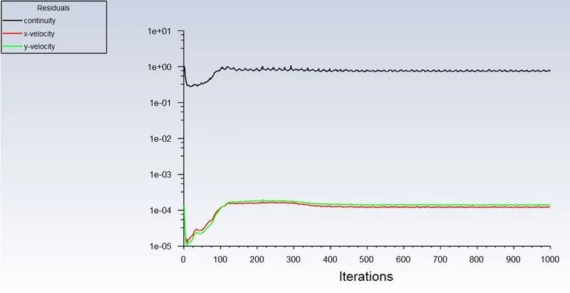
- Residual Scaled Graph for Re 100000 – Steady
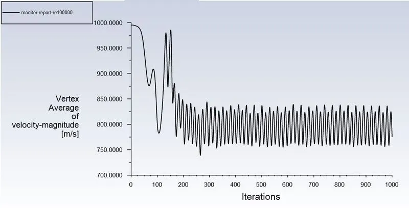
- Area Vertex Monitor Point for Re 100000 – Steady
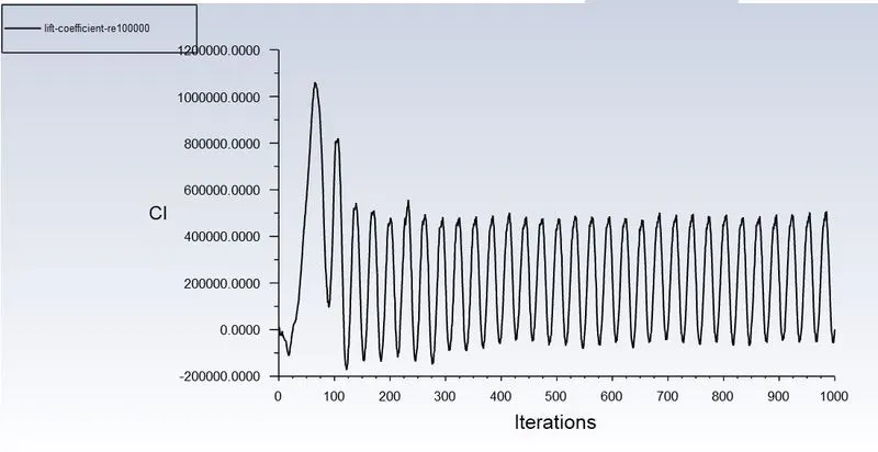
- Lift Coefficient for Re 100000 – Steady
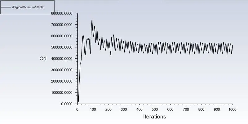
- Drag Coefficient for Re 100000 – Steady
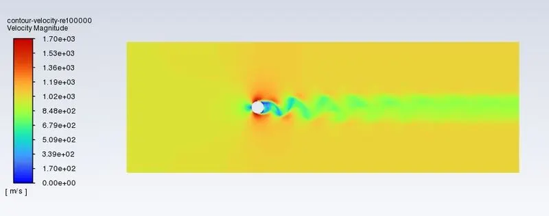
- Velocity Contour for Re 100000 – Steady
Video Link: Re 100000 - Steady
5. Discussion of Results and Conclusion
The problem is about simulating the flow over a cylinder for both Steady State and Unsteady State conditions by varying the Reynolds Number (Re) as mentioned below to understand the Vortex Shedding effects in the flow. This objective is needed to be achieved using Fluent Solver.
From the above simulations, it has been observed that the vortex shedding appears earlier with respect to increment of Reynolds Number by increasing the velocity. Because of this a conclusion can be derived that instability is directly proportional to change in Reynolds Number. Also, the solution becomes unstable and Relaxation Factor has to be varied in-order to get a Stable Solution.
It is also observable that with this increse in Velocity by increasing the Reynolds Number, the values of Lift and Drag Coefficient also increases and due to these reasons, to get a stable solution for these cases more number of iterations are to be performed.
6. References
- King, R., 1977. A review of vortex shedding research and its application. Ocean Engineering, 4(3), pp.141-171.
- Zdravkovich, M.M., 1996. Different modes of vortex shedding: an overview. Journal of fluids and Structures, 10(5), pp.427-437.