Week 8 - Simulating Cyclone separator with Discrete Phase Modelling
1. Introduction
The rotational force produced by a whirling flow stream is used by vortex to extract the particles by dispersing them out from carrier flow stream. Cyclones are some of the most often used particle removal devices (in the industries like Thermal Power Plant) due to its straightforward functionality, minimum maintenance, and flexibility to a broad variety of operational circumstances, such as diameters and flow velocity. Cyclones may be modified for usage in high temperature, high pressure, and corrosive gas running situations by employing the right design techniques and the usage of the materials.
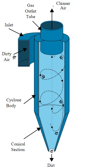
The design of cyclone separators may be ineffective as a result of inaccurate cyclone efficiency prediction. Cyclone behaviours models are often experimental. Since experimental cyclone models are only relevant to particular cyclone configurations, it is still essentially a process of trial and error.
Following are four models:
- Iozia and Leith Model: A modified version of the Barth model, the Iozia and Leith logistic model was created centered on the conditions of force balance. A particle transported by a swirl is said to be subject to two forces: Centrifugal and a Flow Resistance.
- Li & Wang Model: The Li and Wang model incorporates unstable dispersion near the cyclone wall as well as particle bounce. It is possible to represent the dispersion of particles in the cyclone analytically in two dimensions.
- Koch & Licht Model: The Koch and Licht collection hypothesis identified the dispersion of gas residence periods inside vortices as well as the intrinsically unstable character of vortices. Particle mobility in the entrance and collecting zones is described by Koch and Licht.
- Lapple Model: Despite taking into account fluid viscosity, the Lapple model was established based on boundary conditions of force balance like Iozia and Leith Model. Lapple made the supposition that a particle entering the vortex is dispersed uniformly over the inlet hole. The particle is efficiently captured with almost half of the efficiency when it passes from the input half width to the cyclone wall.
2. Problem Statement
- To write a few words about any four empirical models used to calculate the cyclone separator efficiency.
- To perform an analysis on a given cyclone separator model by varying the particle diameter from 1 μm to 5 μm and calculate the separation efficiency in each case. Discuss the results. (Use both the velocity's as 3m/sec).
- To perform an analysis on a given cyclone separator model by varying the particle velocity from 1 m/sec to 5 m/sec and calculate the separation efficiency and pressure drop in each case. Discuss the results. (Use particle diameter size as 5 μm for all cases & keep flow velocity same as particle velocity).
The Boundary Conditions considered for this simulation are,
- Inlet and wall: Reflect
- Outlet (Top): Escape
- Outlet (Bottom): Trap
3. Problem Setup for Simulation
3.1 Geometry Setup
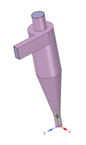
- The Geometric model is received into SpaceClaim for which the volume extraction is performed and the main geometry is suppressed to get the volume into the Mesher.
3.2 Mesh Setup
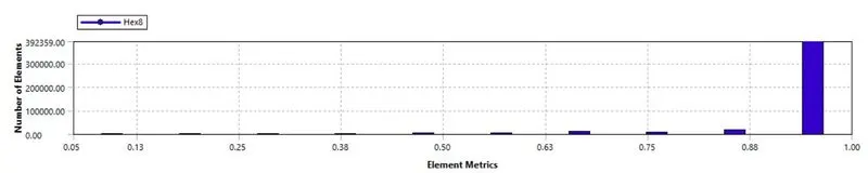
- For this particular case a "Cartesian" mesh has been done in-order to get a uniform mesh throughout the geometry with an element size of 8mm as represented below. The Mesh Quality being above 5%.
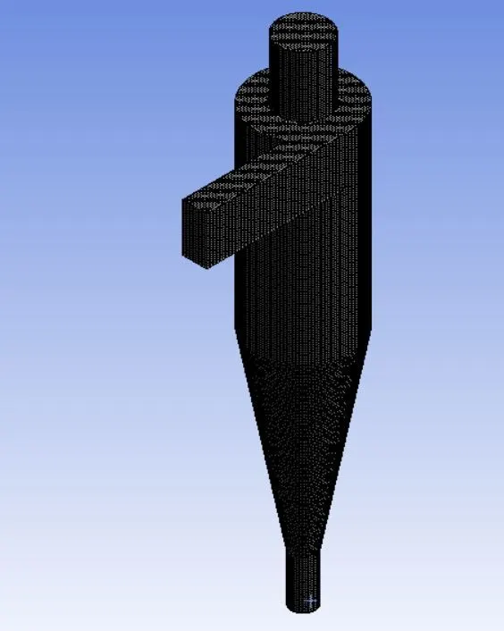
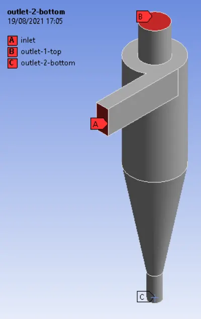
- The Named Sections are given accordingly as represented below.
3.3 Solver Setup
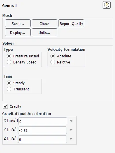
- For Steady State simulation, Steady is selected in the Time Section of the General Tab is to be selected. With gravity being assigned for the particles to settle down.
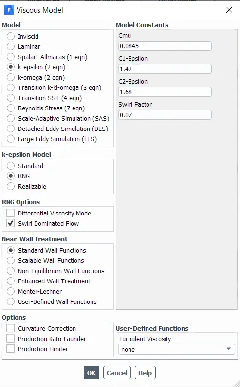
- “K-Epsilon” is used in the Viscous Tab. Along with Swirl Dominated Flow being applied from the RNG Model as represented below.
- Setting up the Discrete Phase Model for interaction with a coupled flow as the Particles will be interacting with the flow within the volume with an Anthracite Material Injection.
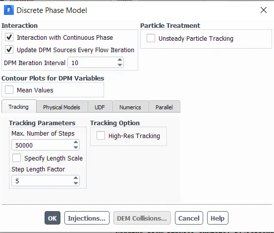
- The sizes of the Anthracite material particles & velocities of particles have to be inserted into Injections dialogue box. This is the place where all the variation to the input data in-terms of numerical values needs to be done as per the objective. The injection type has been selected as surface.
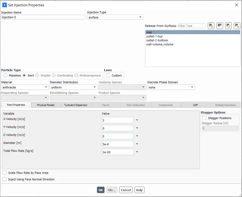
- As per the Boundary conditions considered, these needs to be changed in the DPM Section of each Boundary.
- Number of Iterations is set to 300 and the calculation is run.
4. Simulation Results
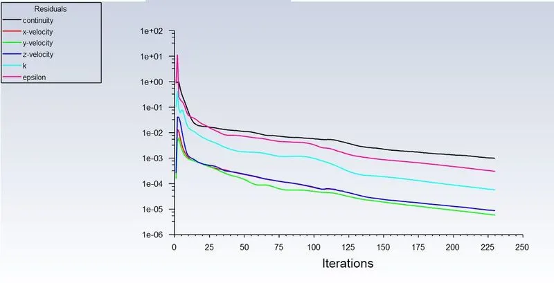
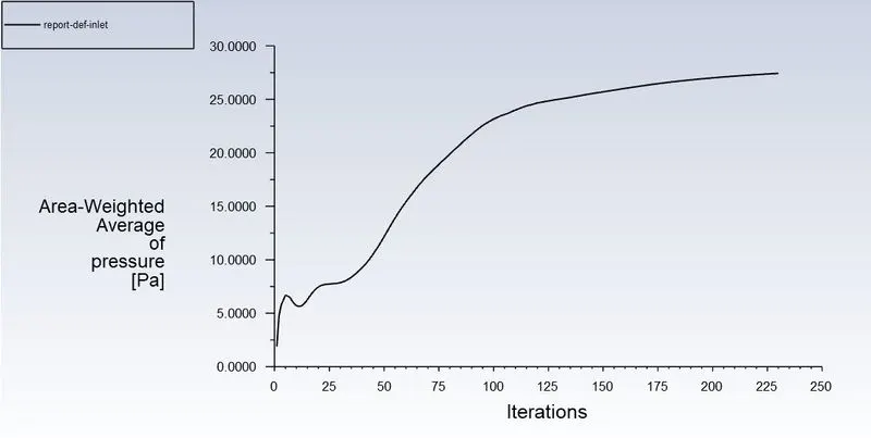
Following are the Simulation results put forward for Constant Velocity and Particle Diameter of 4e-06 as the simulation procedures are considered to be same for all the remaining factors except for change in Particle Dimeter and Inlet Velocity respectively. These have been represented and the remaining results has been tabulated in the Results section
- Residual Scaled Graphs for Particle Size: 4e-06
- Area Weighted Average of Total Pressure at Inlet for Particle Size: 4e-06
- Area Weighted Average of Total Pressure at Top Outlet for Particle Size: 4e-06

- Particle Track DPM for Particle Size: 4e-06

- Particle Time Track Contour for Particle Size: 4e-06
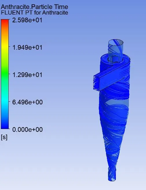
- Particle Time Track Animation for Particle Size: 4e-06
Particle Time Track Animation for 4e-06
5. Discussion of Results and Conclusion
Below are the results for different Particle Diameters for which the efficiency of the Cyclone Separator has been measured.
|
S. No. |
Particle Diameter (m) |
Particle Tracked |
Particle Trapped |
Particle Escaped |
Particle Incomplete |
Efficiency (%) |
|
1 |
1e-06 |
378 |
116 |
262 |
0 |
30.68 |
|
2 |
2e-06 |
378 |
268 |
80 |
30 |
70.89 |
|
3 |
3e-06 |
378 |
297 |
79 |
2 |
78.57 |
|
4 |
4e-06 |
378 |
315 |
62 |
0 |
83.33 |
|
5 |
5e-06 |
378 |
334 |
44 |
0 |
88.35 |
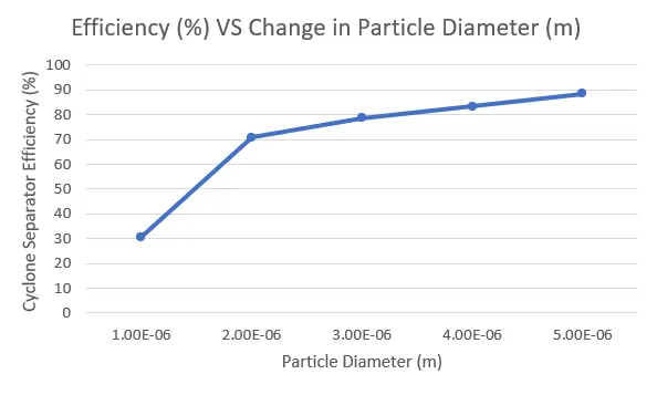
From the above table of Separator efficiency, it can be observed that the efficiency seems to increase with the increase in the particle size for the same velocity inlet. This can be understood that as the particle diameter increases, their mass increases tending towards trapping more amount of particles for a constant velocity
|
S. No. |
Particle Velocity (m/s) |
Particle Tracked |
Particle Trapped |
Particle Escaped |
Particle Incomplete |
Efficiency (%) |
|
1 |
1 |
378 |
98 |
280 |
0 |
25.92 |
|
2 |
2 |
378 |
325 |
46 |
7 |
85.97 |
|
3 |
3 |
378 |
334 |
44 |
0 |
88.35 |
|
4 |
4 |
378 |
345 |
197 |
0 |
91.26 |
|
5 |
5 |
378 |
352 |
209 |
0 |
93.12 |
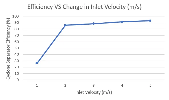
From above table for the variation in the particle velocity, it can be observed that as the flow velocity increases with each simulation and the particle size being constant at 5e-06 m, the increase in the efficiency is observed to be highly substantial from 1 m/s to 2 m/s and then increases steadily.
Coming to the Pressure Drops, the pressure Drop values have been derived from the simulation with the same procedure mentioned above. It can be observed from the simulations that the total Pressure Drop (Pressure Inlet - Pressure Top Outlet) for all the velocity variation increases with the increase in the Velocity which has been tabulated in the below table.
| S. No. | Particle Velocity (m/s) | Pressure Inlet (Pa) | Pressure Top outlet (Pa) | Pressure Drop (Pa) |
| 1 | 1 | 0.94 | 0 | 0.94 |
| 2 | 2 | 5.6885 | 0.004 | 5.68 |
| 3 | 3 | 11.923 | 0.01 | 11.91 |
| 4 | 4 | 19.05 | 0 | 19.05 |
| 5 | 5 | 30.05 | 0 | 30.05 |
This Pressure Drop is represented with a graph as below.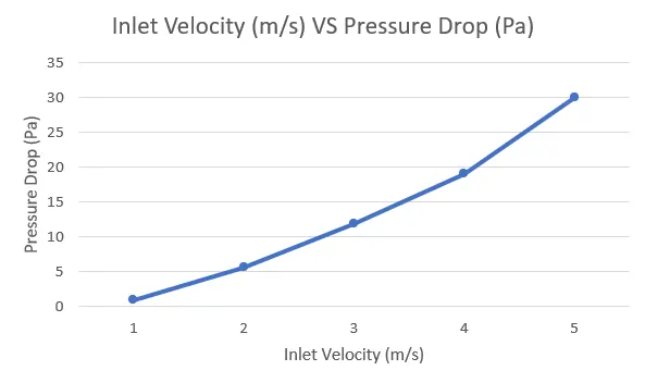
This obtained graph of Inlet Velocity VS Pressure Drop is comparable to the reference graph with Experimental and Numerical Values for the same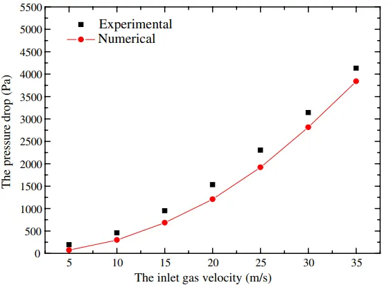
From the above observations, it can be concluded that the parametric study of particle sizes and the flow velocity plays a major role in calculating the efficiency of the separator and has a significant effect on the pressure.
6. References
- Gimbun, J., Chuah, T.G., Choong, T.S. and Fakhru'l-Razi, A., 2005. A CFD study on the prediction of cyclone collection efficiency. International Journal for Computational Methods in Engineering Science and Mechanics, 6(3), pp.161-168.
- Wang, B., Xu, D.L., Chu, K.W. and Yu, A.B., 2006. Numerical study of gas–solid flow in a cyclone separator. Applied Mathematical Modelling, 30(11), pp.1326-1342.