Week 9 - Parametric study on Gate valve.
OBJECTIVE:
For this challenge, We will perform a parametric study on the gate valve simulation by setting the opening from 10 % to 80% considering the following points:
- Obtain the mass flow rates at the outlet for each design point.
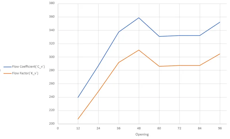
- Calculate the flow coefficient and flow factor for each opening and plot the graph.
- Discuss the results of the mass flow rate and flow coefficient.
THEORY AND INTRODUCTION:
Gate Valve:
A gate valve often referred to as a sluice valve, opens by raising a barrier (gate) out of the flow of fluid's passage. When the gate is fully opened, gate valves barely hinder the flow of fluid and take up very little space along the pipe axis. The gate faces are typically wedge-shaped but might be parallel (in order to be able to apply pressure on the sealing surface).
Instead of controlling flow, gate valves are utilised to stop the liquid flow. The standard gate valve has extremely little flow resistance because, when fully open, there is no blockage in the flow stream. As the gate is shifted, the size of the open flow path often varies in a nonlinear way. This translates to an uneven shift in flow rate with stem travel. The fluid movement may cause a partially open gate to vibrate depending on the construction.
Flow Coefficient:
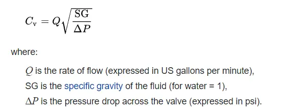
A device's flow coefficient provides a comparative evaluation of how well it facilitates fluid flow. It explains the connection between the corresponding flow rate and the pressure drop via an orifice valve or other component.
The flow coefficient `C_v` often known as the flow-capacity rating of the valve, can be mathematically stated as:
Flow Factor:
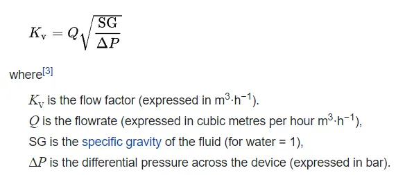
Flow Factor is the same physical quantity but calculated with metric units:
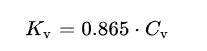
`K_v` and `C_v` are related as follows:
GEOMETRY:
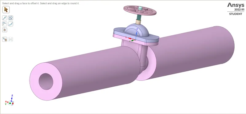
We have the model of a Gate Valve:
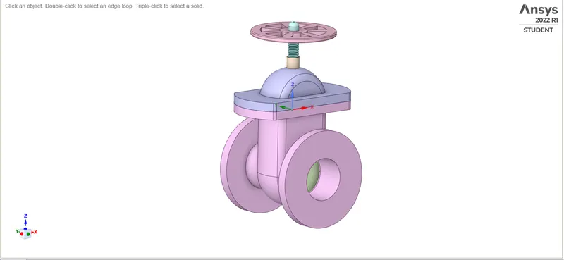
We will extrude the inlet and outlet to better visualise the pressure and velocity effect:
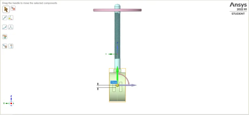
Next, move the gate disk using the move tool:
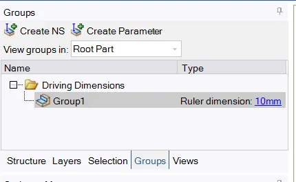
and create a corresponding parameter:
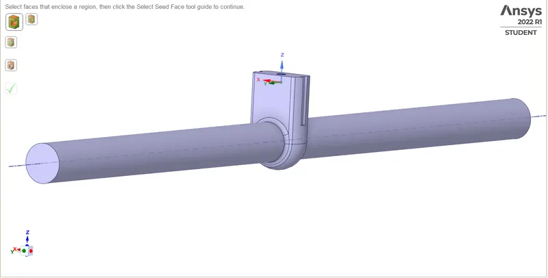
Lastly, we will extract the volume of the resulting geometry, this result will act as our simulation model:
MESHING:
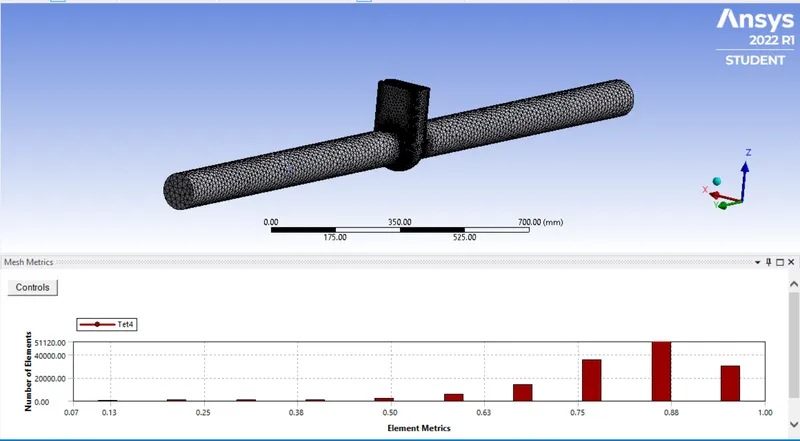
We just create a 50mm tetrahedral mesh for this case:
SETUP:
General Setup:
We are using a Pressure Based, Steady-State Solver with gravity enabled across the negative Z-axis. Viscous Solver is the realizable k-epsilon model with scalable wall functions.
Material: Liquid-Water (ANSYS Default)
Boundary Conditions: Pressure-inlet at 10 Pa, Pressure-outlet at 0 Pa
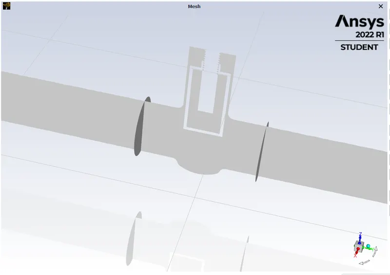
We also create two planes just before and after the valve to measure pressure drop:
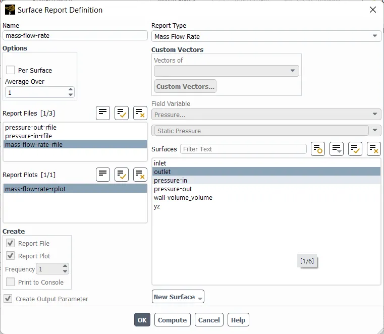
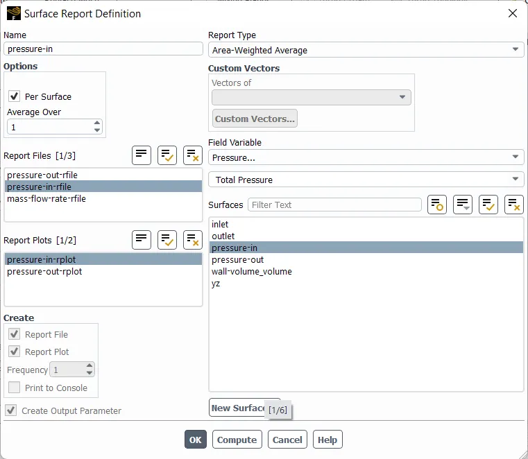
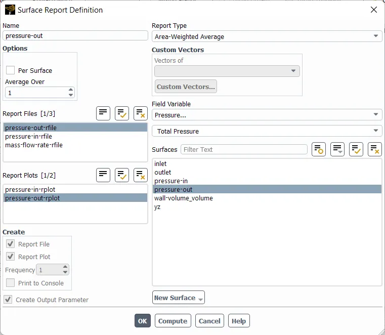
Generate mass-flow rate and pressure-in, pressure-out parameters:
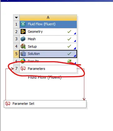
Once the calculation is finished, parameters can be accessed from the parameters tab in the project layout:
RESULTS:
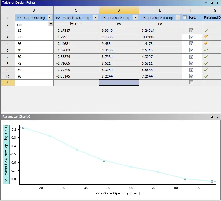
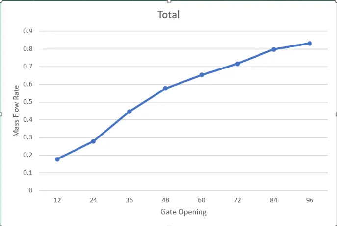
We run the cases for opening 10% - 80%:
| Opening (mm) | Mass Flow Rate (Kg/s) | Pressure-in (Pa) | Pressure-out (Pa) | Pressure Drop (psi) |
| 12 | 0.17817 | 8.2244197 | 7.2644201 | 0.9599996 |
| 24 | 0.27950 | 8.3084209 | 6.6632735 | 1.6451474 |
| 36 | 0.44681 | 8.6210277 | 5.5810919 | 3.0399358 |
| 48 | 0.57688 | 8.7933761 | 4.3097455 | 4.4836306 |
| 60 | 0.65374 | 9.4185888 | 2.6414559 | 6.7771329 |
| 72 | 0.71666 | 9.4880012 | 1.4178043 | 8.0701969 |
| 84 | 0.79748 | 9.1335232 | -0.84860013 | 9.98212333 |
| 96 | 0.83145 | 9.9048723 | 0.24013837 | 9.66473393 |
Converted Data:
| Mass Flow Rate(GPM) | Pressure-Drop(Psi) | Flow Coefficient(`C_v`) | Flow Factor(`K_v`) |
| 2.823997512 | 0.000139236 | 239.324898 | 207.0160367 |
| 4.430081974 | 0.000238609 | 286.7929383 | 248.0758916 |
| 7.08193644 | 0.000440906 | 337.2709357 | 291.7393594 |
| 9.143597928 | 0.000650297 | 358.5595607 | 310.15402 |
| 10.36182687 | 0.000982942 | 330.5007346 | 285.8831354 |
| 11.3591282 | 0.001170485 | 332.0183099 | 287.1958381 |
| 12.6400775 | 0.001447787 | 332.1982725 | 287.3515057 |
| 13.17847695 | 0.001401754 | 351.9892248 | 304.4706795 |
CONCLUSION:
- As we see from the result, the flow coefficient and flow factor vary randomly with opening distance and follow no consistent trend.
- Similarly, the mass flow rate also does not follow a linear relationship with the opening.
- This is the primary reason why Gate Valves are used as devices to stop fluid flow rather than controlling the flow of fluid in pipes.