Week 9 - Parametric study on Gate valve.
Aim:
To perform a parametric study on the gate valve simulation.
Objective:
By setting the opening to between 10 % - 80 % and performing the parametric study on the gate valve simulation we study for the following results,
- Obtain the mass flow rates at the outlet for each design point.
- Calculate the flow coefficient and flow factor for each opening and plot the graph.
- Discuss the results of the mass flow rate and flow coefficient.
Introduction:
Gate Valve:
Gate valves are designed for fully open or fully closed service. They are installed in pipelines as isolating valves and should not be used as control or regulating valves. Operation of a gate valve is performed doing an either clockwise to close (CTC) or clockwise to open (CTO) rotating motion of the stem. When operating the valve stem, the gate moves up- or downwards on the threaded part of the stem.Gate valves are often used when minimum pressure loss and a free bore is needed. When fully open, a typical gate valve has no obstruction in the flow path resulting in a very low pressure loss, and this design makes it possible to use a pipe-cleaning pig. A gate valve is a multiturn valve meaning that the operation of the valve is done by means of a threaded stem. As the valve has to turn multiple times to go from open to closed position, the slow operation also prevents water hammer effects.
Working:
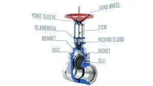
A gate valve is a multiturn valve meaning that the operation of the valve is done by means of a threaded stem. As the valve has to turn multiple times to go from open to closed position, the slow operation also prevents water hammer effects. When fully open, a gate valve has no obstruction in the flow path and so has a very low pressure drop. If the fluid is very viscous a special type of gate valve known as a knife gate valve can be used. One reason that gate valves are not normally used to regulate flow is that the flow rate of the fluid is not proportional to the amount that the valve is open. Moreover, a partially open gate valve may suffer from vibration in which the valve may move from its assigned position. Also the gate and seat may be subject to excessive wear if the valve is partially open.
Automated gate valves exist with either an electric or pneumatic actuator, but a manual gate valve is cost-effective since gate valves are typically used infrequently. Gate valves are also commonly referred to as sluice gate valves.
Body - The valve body is the pressure retaining part and also houses other parts.This also provides passage to flow from the valve, its end connection is piping this end can be but welding type, threaded, and many more depends upon the size and pressure of the piping system.
Bonnet - It is the second pressure retaining part of the valve. It is also called a cover. We can connect it with the system by bolting, welding, or threading to create a valve enclosure. In case of the gate, stop, diaphragm wall it has the opening so that the valve stream and pass through it. Bonded provides access to valve internals during maintenance.
Disc - This is is the part that allows throttles or stops flow on its position. In the case of a plug or ball valve, the disk is called a plug or ball. A disc is seated against the stationary wall seat or seats when the wall is in the closed position. It can be moved away from the valve seat by the motion of the valve string which the exception of the check valve and safety relief valve in which the disc is moved away from its seat by the fluid flow and pressure.
Seat - This is one of the main components of the system which directly affects the leakage rate of the valve. One of the integral to valve body is made up of forged metallic rings or non-metallic rings. All valves may have one or more seats. In the case of the globe and swing check valve, there is one seat.
Stem - Stem is a forged solid rod or shaft. The valve steam transferred the required motion of the disc plug or valve for opening and closing of the valve.
Actuators - The actuator is a mechanism that operates the valve. It is connected to the stem and disc assemble. It may be manually operated by handwheel, manual lever, gear, chain or it can be operated through motor and solenoid.
Parametric Study -
This option alows us to simulate the model for numurous iteration of a parameter, this parameter could be length ,height,density ,velocity etc.. When simulatein using this option ww will only simulate for the first case the remaining cases will be done by ANSYS once we mention the values the model should be iterated for. Also not alone the input we can create our required output as an parameter too, in this way in less time we will be able to obtain didtinct results for each inputs. Furtheron we can obtain the results of simulated input parameters directly from solution tab.
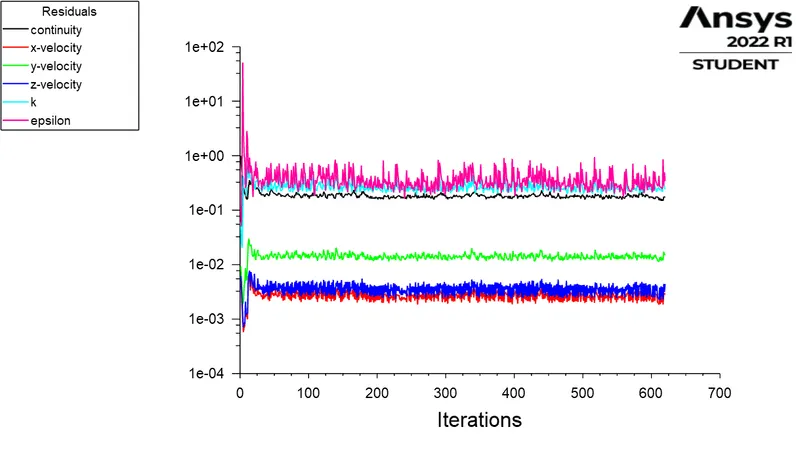
To use this we first need a parameter for which we need to simulate several times using different values to study. Then we enable the parametric option for that paticular parameter this will be the input parameter ,in this model it is the rise in disc height in mm. Then in solution setup we enable the same option for the output we want to study for, in our case it is the mass flow rate. Thereafter we proceed as usual with the simulation.
Flow Co-Efficient -
The flow coefficient of a device is a relative measure of its efficiency at allowing fluid flow. It describes the relationship between the pressure drop across an orifice valve or other assembly and the corresponding flow rate. A flow-coefficient (Cv) is a commonly used parameter for the design of flow devices like control valves, flow meters, sprinklers etc. Therefore the Cv tells you how to properly size your valve so it has minimal effect on the hydraulic efficiency you’ve engineered into your system.
Mathematically the flow coefficient Cv (or flow-capacity rating of valve) can be expressed as :

Where,
Q = Flow rate (gallons/min)
SG = Specific gravity (water=1)
`Delta P` = Pressure drop across valve (psi)
Flow Factor:
The metric equivalent of the flow coefficient - Cv is based on the SI-system and is called the Flow Factor - Kv .
Where,
- Kv = flow factor (expressed in m3·h−1).
- Q = flowrate (expressed in cubic metres per hour m3·h−1),
- SG = Specific gravity of the fluid (for water = 1),
- ∆P = differential pressure across the device (expressed in bar).

The relationship between Cv and Kv can be expressed as,
- Cv = 1.16 Kv
- Kv = 0.862 Cv
Geomentry :
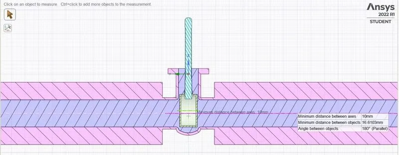
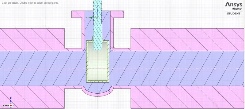
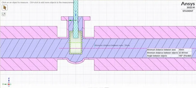
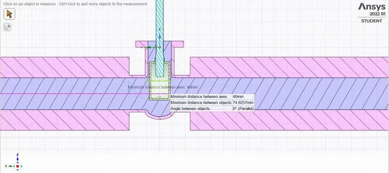
We import the solid gate valve model to space claim and we hide the outer parts like the actuatore and bonnet as it is not necessary for our simulation. Then we extract the fluid volume by selecting the region where the fluid have contact. We select the inlet , outlet and the entire height from the base till the bonnet edge as the volume to be extracted.
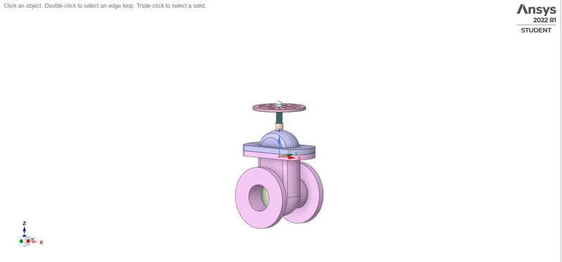
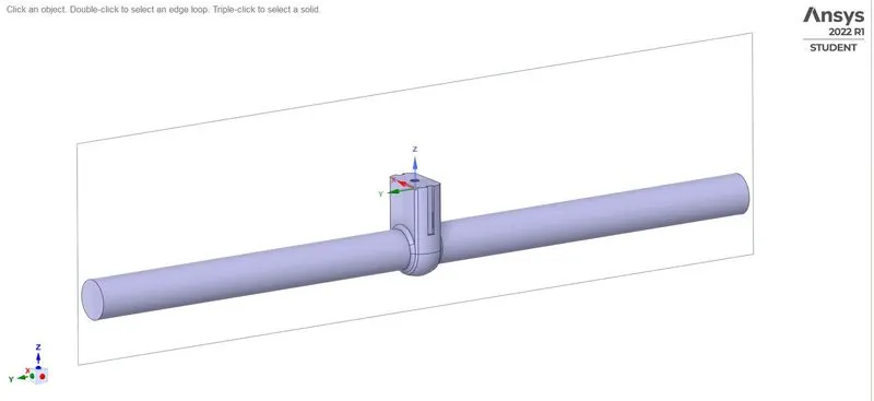
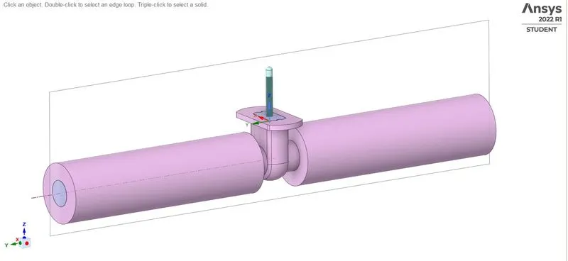
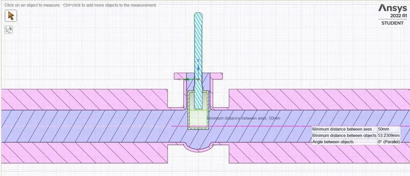
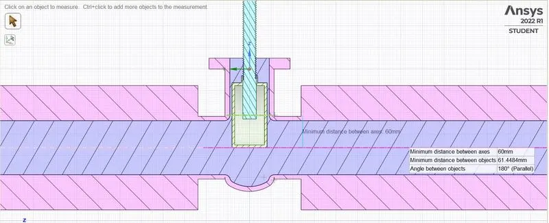
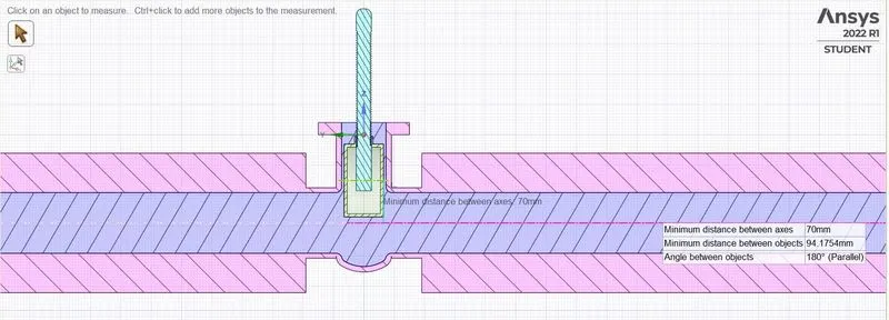
For the parametric study we select the entire body of the disc and using pull option we pull up the disc above to 10 mm from its fully closed position. Then we open the group option and select create parameter to make this as a parameter.

While extracting volume we make the spindle,bottom and gate disk visible as it interacts with the fluid volume to be extracted. And once extracted we suppress every parts except the extracted volume.
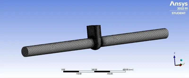
Mesh :
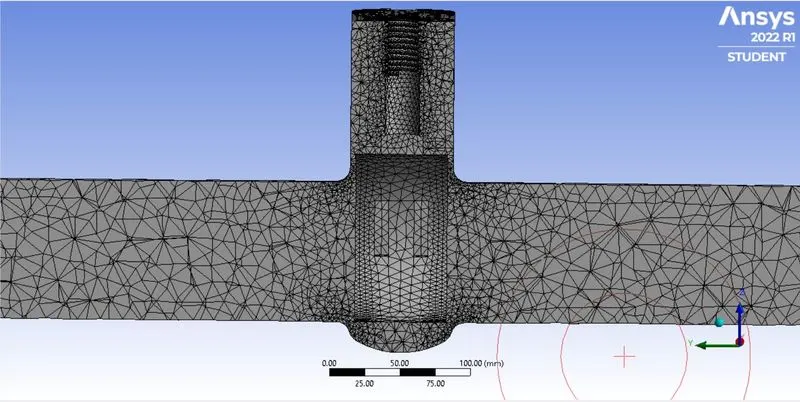
We used a mesh size of 90 mm
No.of Elements - 138103
Setup:
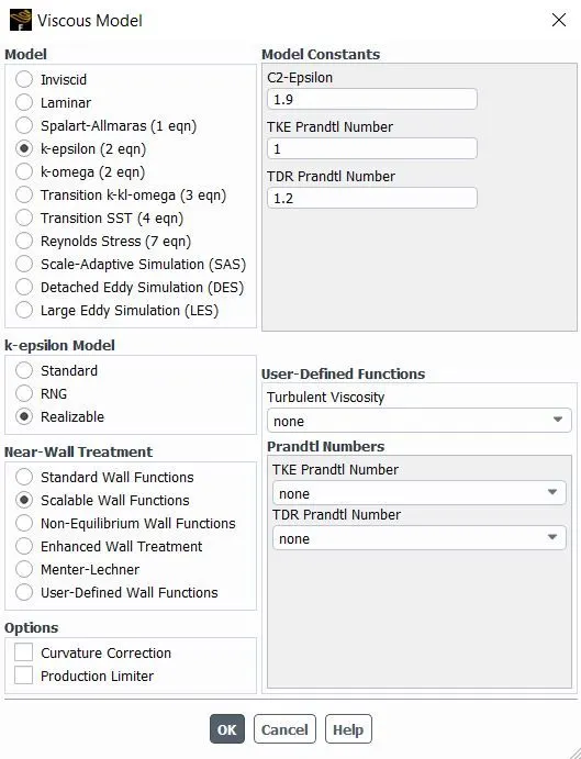
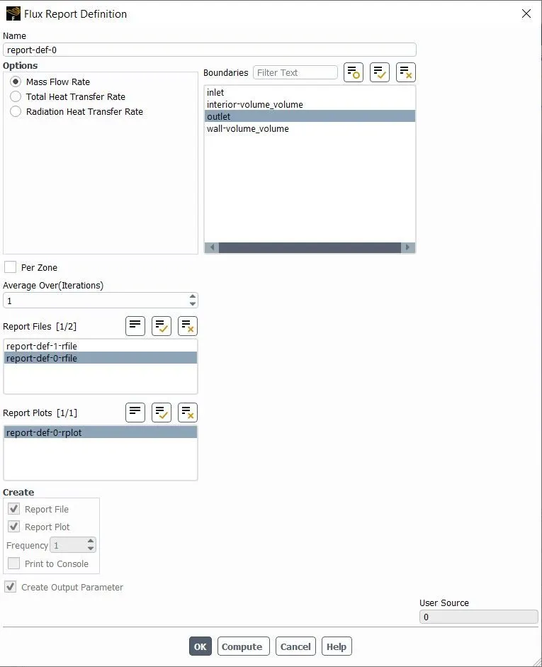
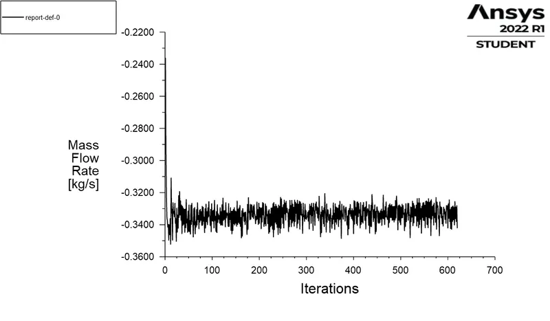
We use k-epsilon model to solve for this gate valve . We use water as the fluid to simulate with. The gravity is alongnegative Y- axis.Then we mention the boundary conditions , inlet as pressure inlet at 10 pa. We then creat a plot for mass flow rate at outlet, and while creating we also mention this mass flow rate as an output parameter. By doing this we will obtine the output mass flow rate for every input of gate valve opening.
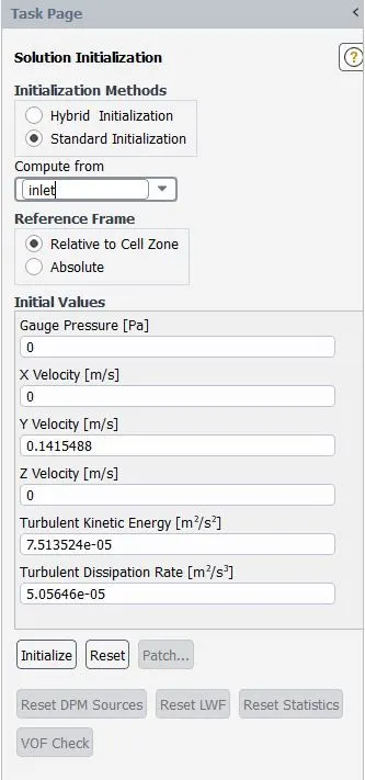
As mentioned earlier this is a pressure inlet and we can calculate the inlet velocity only when initialise the solution as standard initialization. By this way the ansys calculates the velocity as 0.1415488 m/s . From this
`Re = (rho*D* V)/ mu`
= `(1000*0.1*0.1415488 ) / 0.001003`
Re = 14112.5423 , Therefore the flow is turbulant.
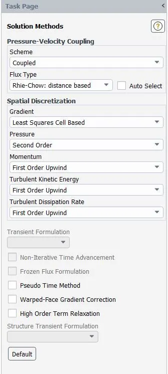
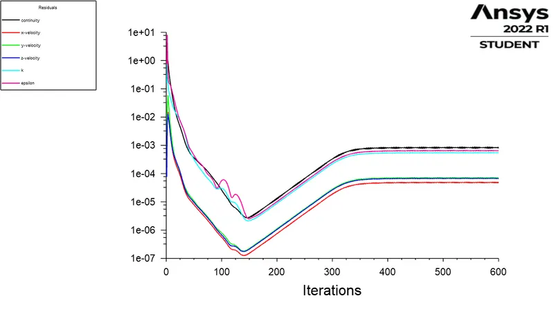
We use First order couples method to solve the equations.
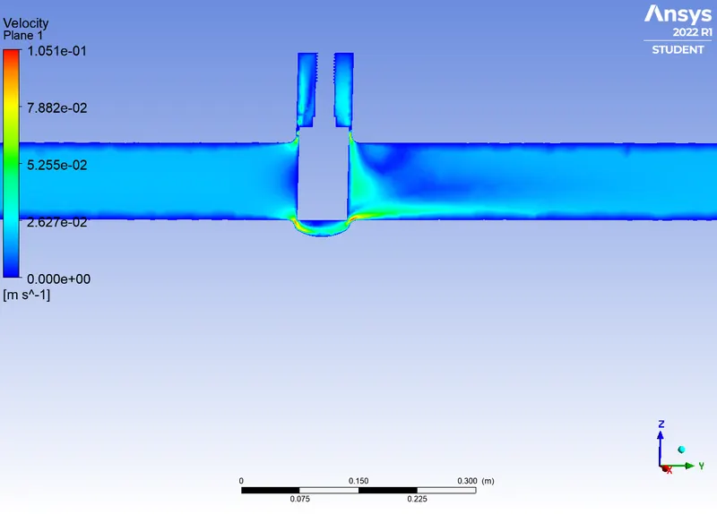
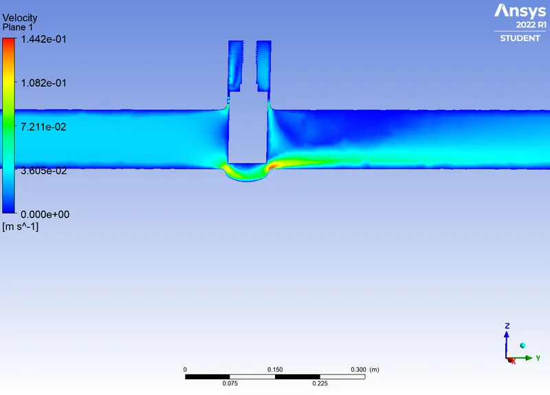
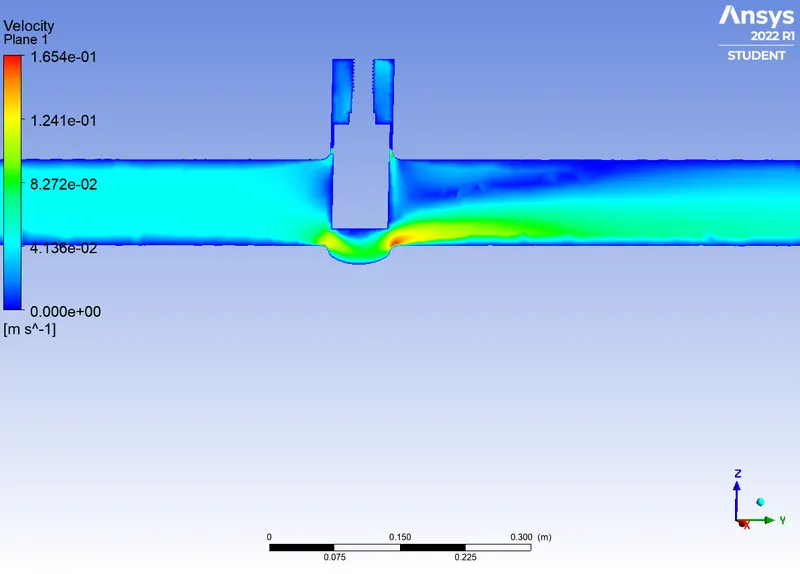
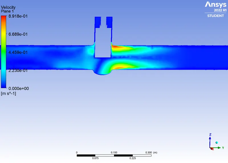
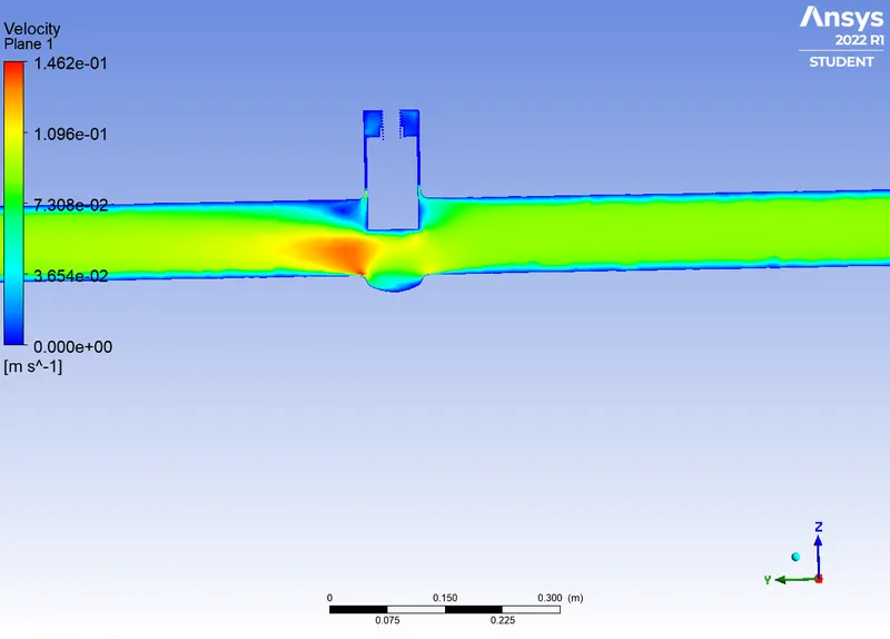
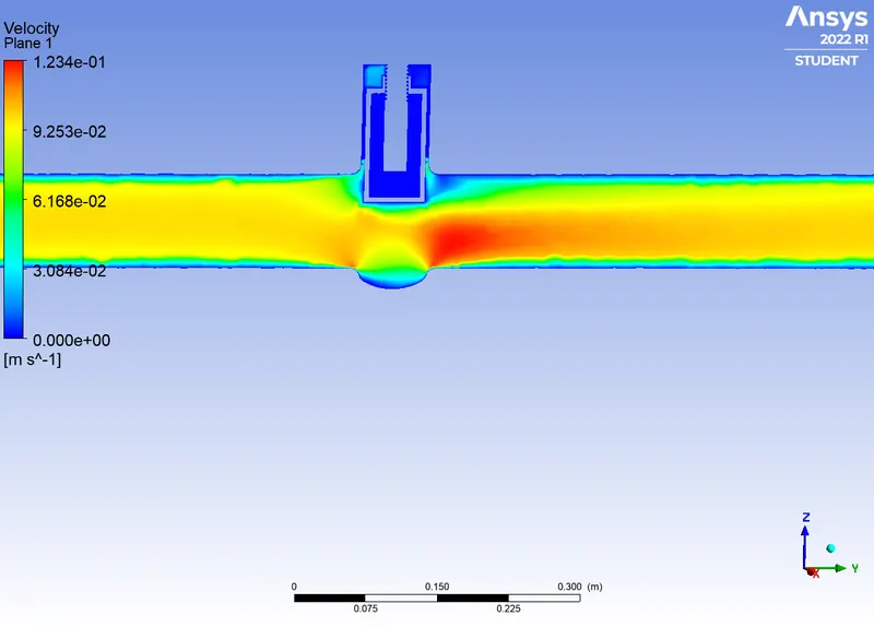
Finally we create a velocity contour to visuvalise the changes in the valve disk region.
Results:
Since we have done the parametric study we do not need to simulate for every conditions. We have already mentioned the Input design points as the Lift height of the gate and the output parameter as the Mass flow rate at the outlet. This creates a seperat row in the workbench workflow,
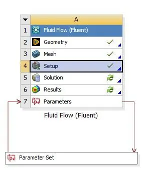
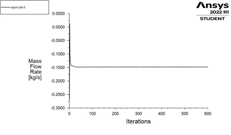
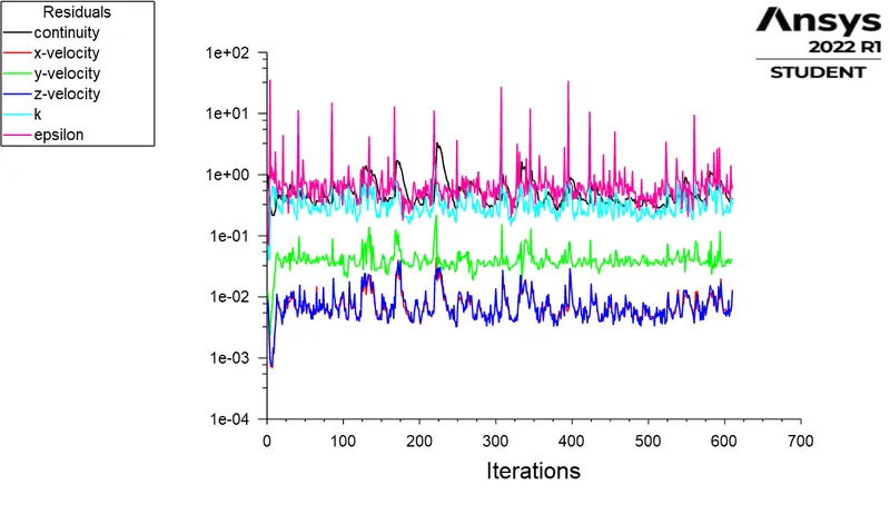
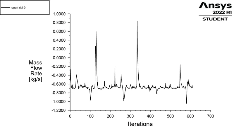
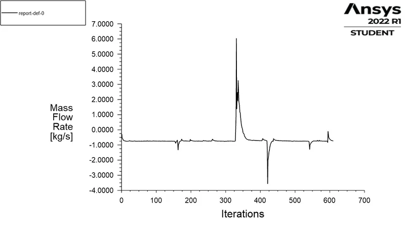
And when once we open the parameter tab after our first simulation we will see only the outputs of a single data poin, because we havint defined for the other points. After opening the parameter tab we click on the first set which in our case 'DP 0' which have the input as 10 mm and right click to duplicate the point, we duplicate it as many times as we require to have all 8 points. Under 'P-1' cloumn which containts the input parameter we type our required points for which we needed the mass flow rate and chech the boxes to retainthe data points value as we need them to obtain their respective plots. Then we click 'update all points' option and ansys starts to calculate the mass flow rate for all the data points. The 'report-def-0' is the mass flow rate plot,
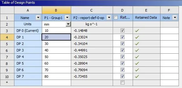
Once the calculation is complete we will obtain the results for each points. To visuvalize the plots for a paticular data point we right click that data point and set it to current. And Ansys updates to that solution and shows the results for that paticular input We then directly open the solution tab and can visuvalize the plots. This reduces us a lot simulation time and makes it easy for us to simulate for case where it requires to iterat with different values for a paticular parameter.
DP 0 :
Local Velocity Contour -
Flow Co-efficient -
Q = 0.14848 kg/s
SG (water) = 1
Pressure Inlet = 10 psi
Pressure Outlet `cong` 0 psi
`Delta P` = (Pi - Po)
= 10 psi
Cv = `0.14848 * sqrt(1/10)`
= 0.020227
Flow Factor -
Kv = 0.865 *Cv
= 0.0174963
DP 1 :
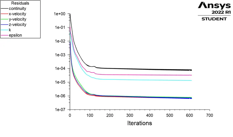
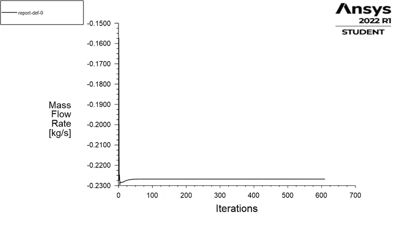
Local Velocity Contour -
DP 2 :
Local Velocity Contour -
DP 3:
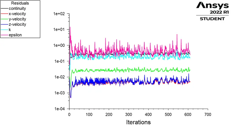
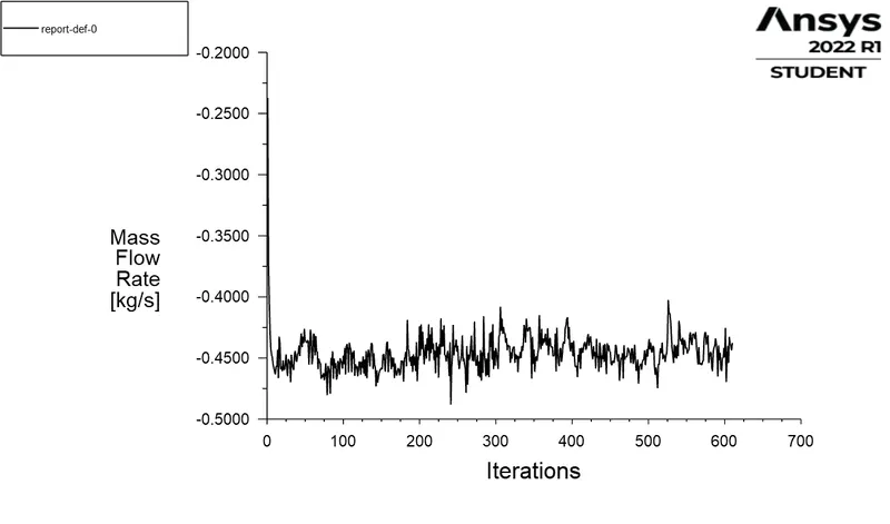
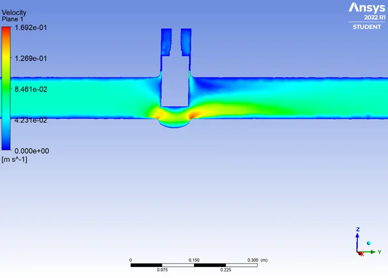
Local Velocity Contour -
DP 4 :
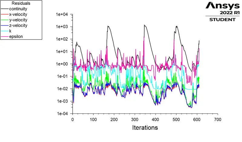
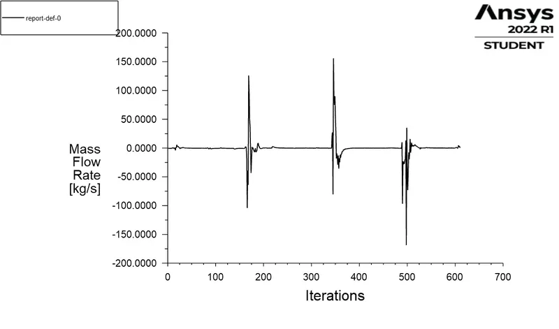
Local Velocity Contour -
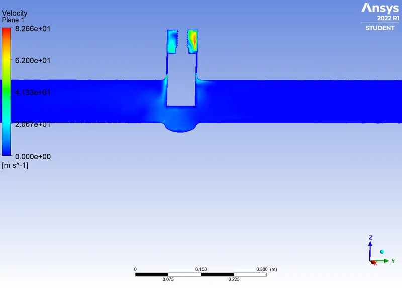
DP 5:
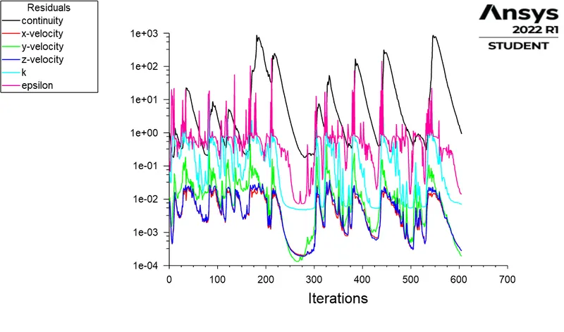
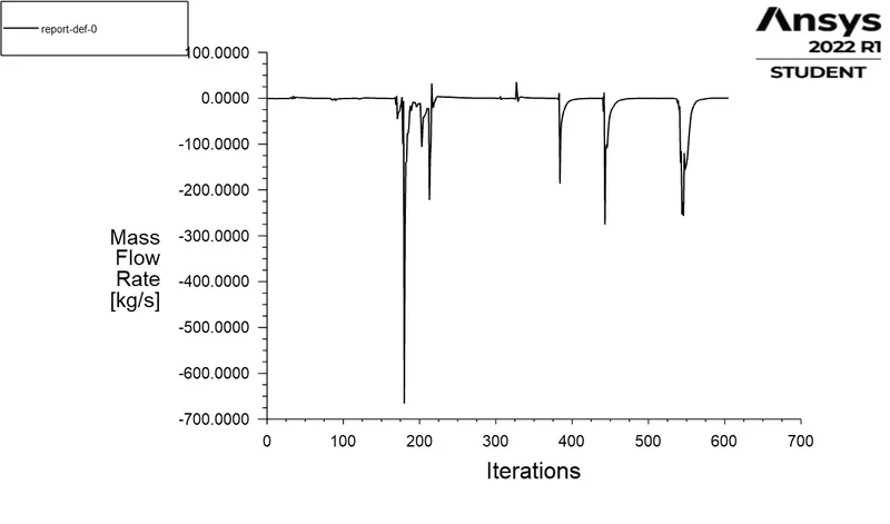
Local Velocity Contour -
DP 6:
Local Velocity Contour -
DP 7:
Local Velocity Contour -
Summary:
| S.No | 1 | 2 | 3 | 4 | 5 | 6 | 7 | 8 |
|
Data Point (mm) |
10 | 20 | 30 | 40 | 50 | 60 | 70 | 80 |
|
Mass Flow Rate (kg/s) |
-0.148488 | -0.23024 | -0.34104 | -0.44991 | -0.35025 | -0.28904 | -0.79094 | -0.73455 |
| Cv | 0.020227 | 0.031365 | 0.046459 | 0.06129 | 0.047713 | 0.039375 | 0.10774 | 0.10006 |
| Kv | 0.01749 | 0.0271307 | 0.0401871 | 0.0530160 | 0.0412724 | 0.0340596 | 0.0932020 | 0.0865571 |
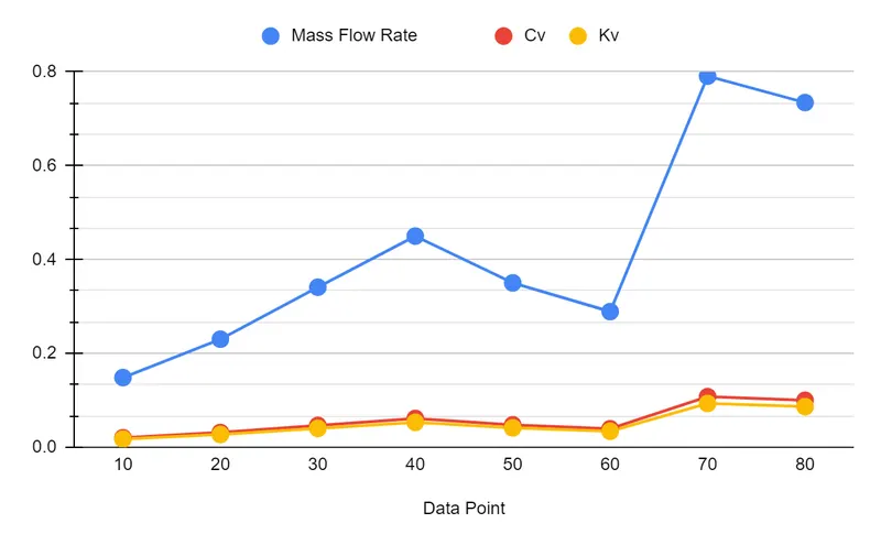
This type of study is useful in reducing the overall simulation time. On Conclusion we can say that the mass flow rate increases with increase in lift of gate valve and is maximum when it is open 80 % , and thus the flow factor and flow coefficient also increases with it. And the calculation of flow co-efficient is helpful in determining the efficiency of each openings.We can observe that from velocity contour that the velocity is high in the region around the disc and the pressure decreases from 10 to almost 0 psi at the outlet. Therefore the study of parametric operation is understood.