Week 9 - Parametric study on Gate valve.
Parametric study on Gate Valve
Aim:
To perform a parametric study on the gate valve simulation by setting the opening from 10 % to 80%.
Objective:
- Obtain the mass flow rates at the outlet for each design point.
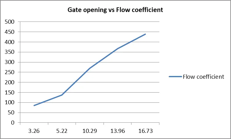
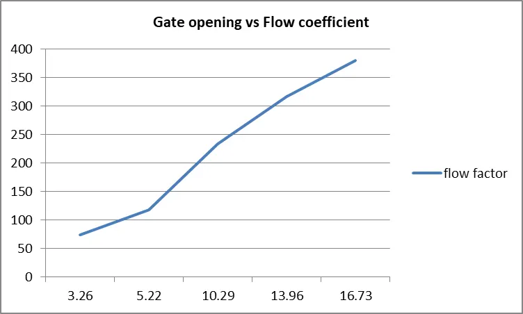
- Calculate the flow coefficient and flow factor for each opening and plot the graph.
- Discuss the results of the mass flow rate and flow coefficient.
Introduction:
A gate valve is a control valve that either allows media to flow through unobstructed or stops the fluid flow. The main advantage of a gate valve is the straight-through unobstructed passageway, which induces minimal pressure loss over the valve. The unobstructed bore of a gate valve also allows for a pig's passage in cleaning pipe procedures, unlike butterfly valves. However, gate valves are slower than quarter-turn valves and should only be used in the fully open or closed position, not to regulate the flow. Automated gate valves exist with either an electric or pneumatic actuator, but a manual gate valve is cost-effective since gate valves are typically used infrequently. Gate valves are also commonly referred to as sluice gate valves.
Gate valve operation
A gate valve operates similar to other valves. To open the valve, turn the handwheel, which moves the gate up or down on the stem via the threads. A gate valve requires more than one 360° turn to open or close the valve fully. When the gate is lifted up, it opens the inlet to the outlet allowing an unobstructed passageway for the media to flow. When the gate is lowered, it closes and blocks the media flow.
The relationship between the gate's vertical travel and the flow rate is nonlinear for a gate valve, with the greatest changes occurring near-complete closure. When used to regulate flow, the relatively high velocity of the flow at partial opening results in gate and seat wear, which along with possible vibrations of the gate, shortens the valve's service life. Therefore, a gate valve should only be used for on/off control.
Gate valve applications
Gate valves have numerous industrial and residential applications.
- Slurries: Gate valves are often used in applications that contain slurries as their media. This is because a gate valve has an unobstructed passageway for the fluid, so the slurry can easily pass through the valve. In addition, knife gate valves can easily cut right through the slurry to close
- Viscous media: Gate valves are commonly used for viscous media like light grease and oils. The unobstructed passageway allows these media to flow easily. The valve can be piged, a common cleaning method for these applications. In addition, valves for these applications are typically on or off for long periods of time.
- Watergate valves: For water applications, water gate valves are commonly used since flow control is typically not done for these applications. The valve can be fully open or fully closed, allowing for proper water control. [1]
Coefficient of flow:
Valve Flow Coefficient (Cv) is the flow capability of a control valve at fully open conditions relative to the pressure drop across the valve. It is defined as the volume of water (GPM in the US) at 60°F that will flow through a fully open valve with a pressure differential of 1 psi across the valve. It is useful to know how to calculate Cv because it is the standardized valve sizing and selection method for control valves used throughout the HVAC industry. The equation used to find Cv is,
`C_v=(Q√G)/√ΔP`
Q = Flow in Gallons per Minute
G = Specific gravity of fluid (estimated as 1 for water systems)
ΔP = Differential pressure over valve (delta P) – stated in psi [2]
Flow Factor:
`K_v=Q√(G/ΔP)`
Kv is the flow factor (expressed in m3·h-1).
Q is the flowrate (expressed in cubic metres per hour m3·h-1),
SG is the specific gravity of the fluid (for water = 1),
∆P is the differential pressure across the device (expressed in bar).
Kv can be calculated from Cv using the equation:
`K_V=0.865 C_v`
Approach and solving:
Parametric study: Parametric study is the approach in which simulation is done automatically for various cases by setting up the parameters for one simulation and then creating various design points. So, every time we do not need to change the geometry, mesh and run the simulation again and again.
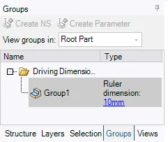
- The simulation for 10% is done by using a parametric study by creating a group in SpaceClaim, and the mass flow rate is calculated in fluent.
- Then by just assigning the design points from 20% to 80% in the parameter window, the mass flow rate is calculated.
PROCEDURE:
- Geometry
- Mesh
- Setup
- Solution
- Results
Pre-Processing:
Geometry:
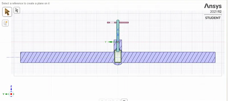
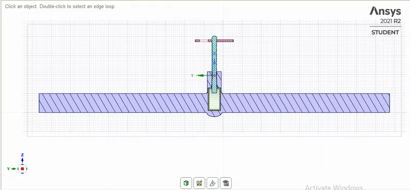
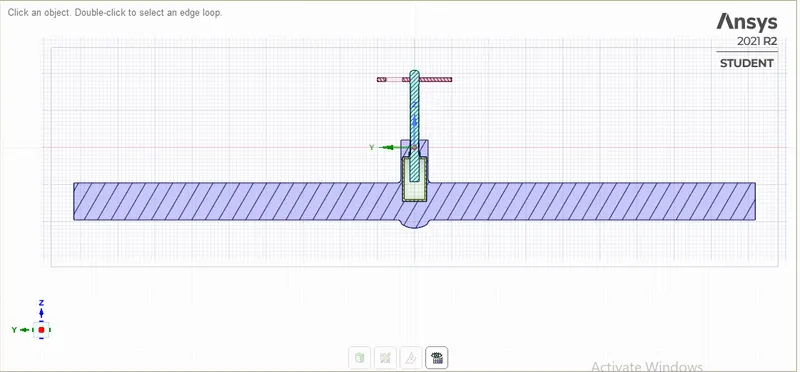
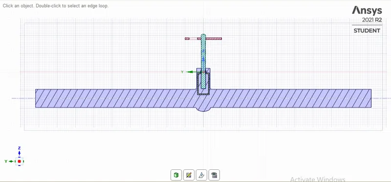
- Import geometry to spaceclaim
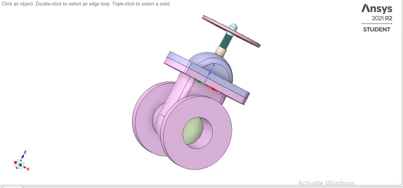
- Moving the gate valve disc for opening
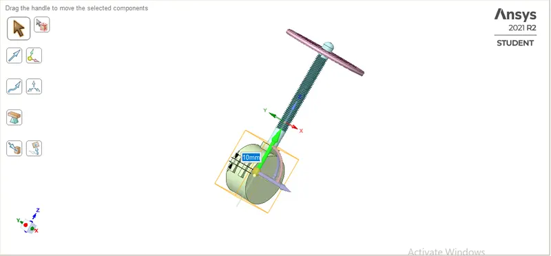
- Create group for parametric study
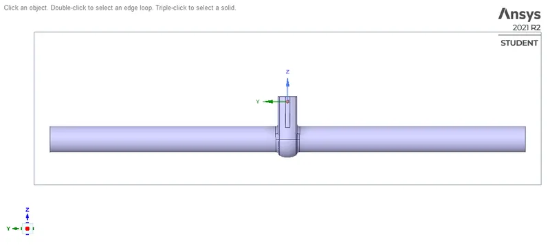
- Pull out the inlet and outlet to examine the flow properly
- Extracting the fluid volume
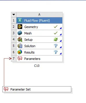
- Parametric window is created
Mesh
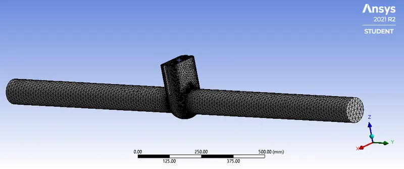
Mesh size: 50mm
No of node: 28961
No of elements: 136252
Setup:
General: Pressure based, absolute, Steady state
Gravity: Z=-9.81
Model: K-epsilon> realizable > Scalable wall functions
Material: Fluid- water
Cell zone: fff_fluidvolume-> material-> water
Boundary condition: inlet-pressure inlet = 10 Pa
Outlet = 0 Pa (1 atm)
Method: Scheme-coupled
Momentum- 1st order upwind
Definitions: flux report > Mass flow rate > outlet
Initialization: Standard initialization
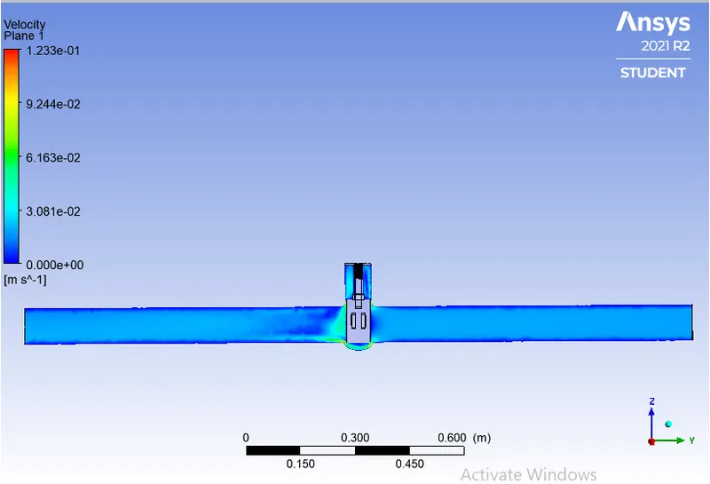
Results: Velocity contour
Run-calculation: 300-iterations
Results
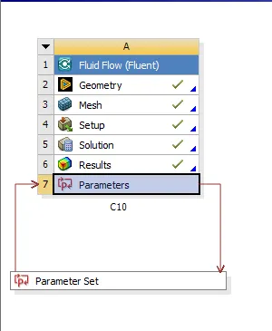
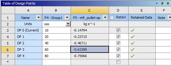
Parameter window created
|
Disc opening (%) |
Design point |
|
10 |
DP 0 |
|
20 |
DP 1 |
|
40 |
DP 2 |
|
60 |
DP 3 |
|
80 |
DP 4 |
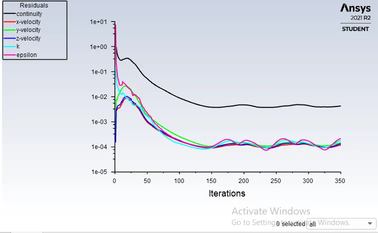
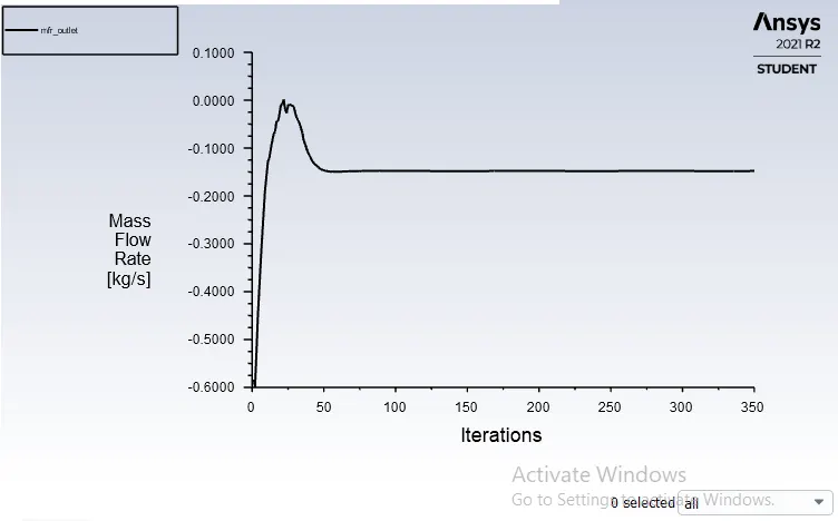
Case 1
Gate disc: 10mm (10%)
Residual
Mass flow rate
Velocity contour
Case 2
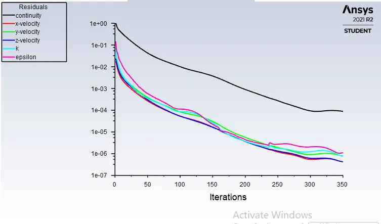
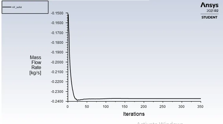
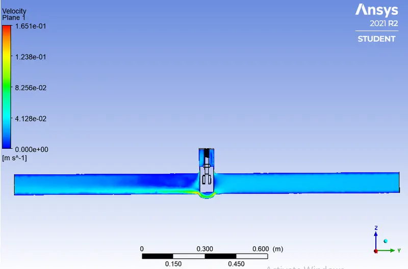
Gate disc: 20mm (20%)
Residual
Mass flow rate
Velocity contour
Case 3
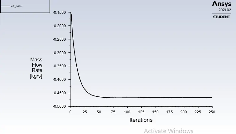
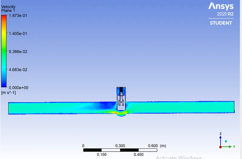
Gate disc: 40mm (40%)
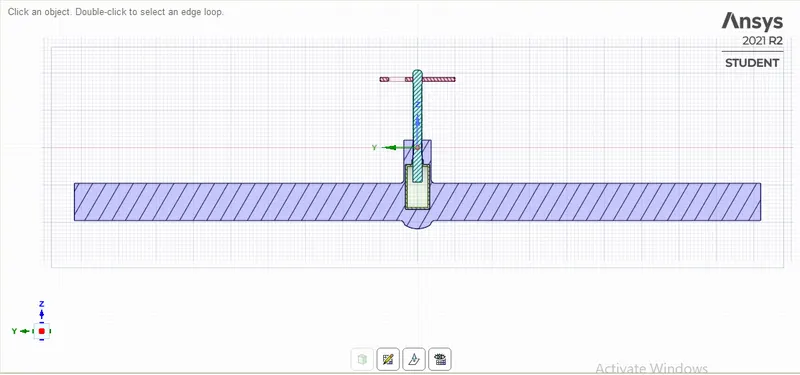
Residual
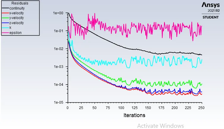
Mass flow rate
Velocity contour
Case 4
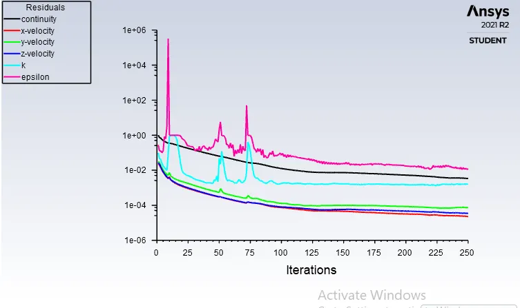
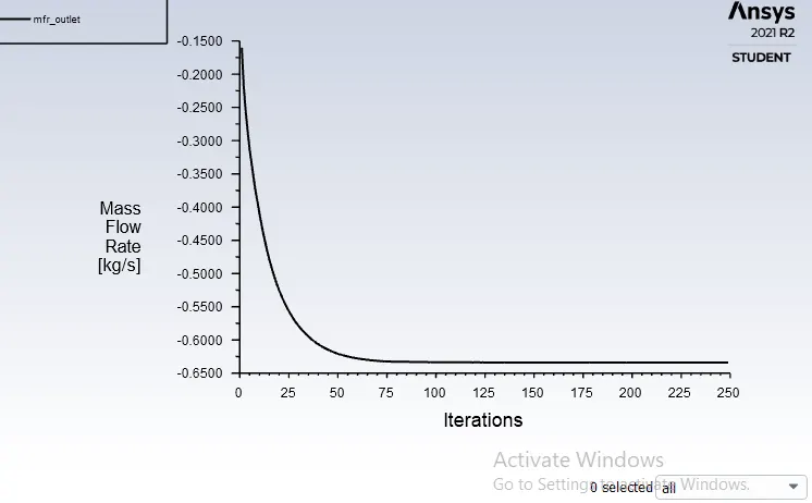
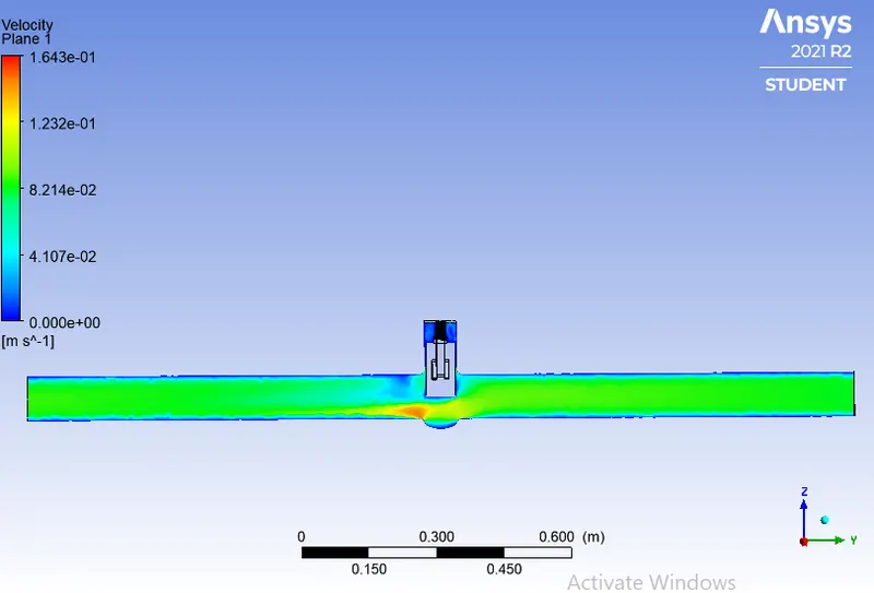
Gate disc: 60mm (60%)
Residual
Mass flow rate
Velocity contour
Case 5
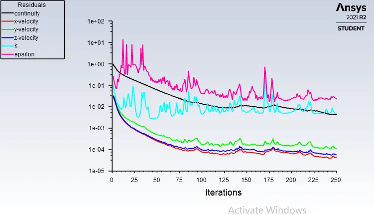
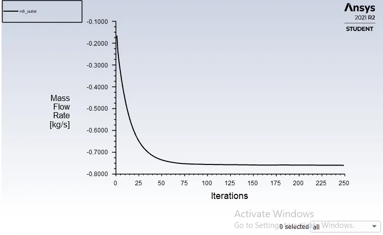
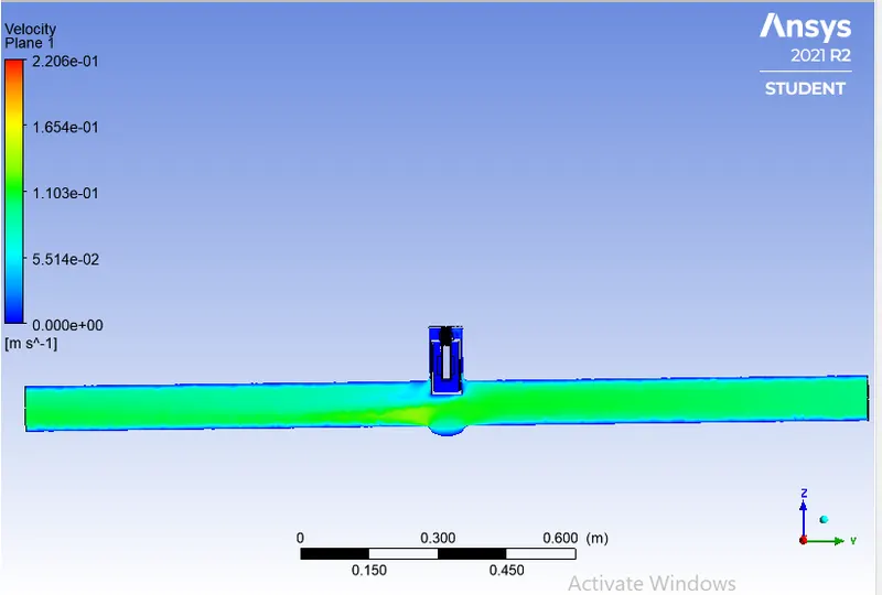
Gate disc: 80mm (80%)
Residual
Mass flow rate
Velocity contour
|
Gate lift (%) |
Mass flow rate (kg/s) Q |
Mass flow rate (gallons/min) |
Specific gravity G |
Pressure difference (Psi) |
Coefficient of flow Cv |
Flow factor Kv |
|
10 |
0.1479 |
3.26 |
1 |
0.00145038 |
85.600 |
74.044 |
|
20 |
0.23715 |
5.22 |
1 |
0.00145038 |
137.065 |
118.56 |
|
40 |
0.46711 |
10.29 |
1 |
0.00145038 |
270.19 |
233.71 |
|
60 |
0.63399 |
13.96 |
1 |
0.00145038 |
366.55 |
317.065 |
|
80 |
0.75966 |
16.73 |
1 |
0.00145038 |
439.29 |
379.98 |
Graphs:
Conclusion:
|
Disc opening (%) |
Mass flow rate at the outlet (kg/s) |
|
10 |
0.1479 |
|
20 |
0.23715 |
|
40 |
0.46711 |
|
60 |
0.63399 |
|
80 |
0.75966 |
- It is observed that the mass flow rate increases with an increase in gate disc opening from 10% to 80%.
- Also, the flow coefficient and flow factor increase with gate opening.
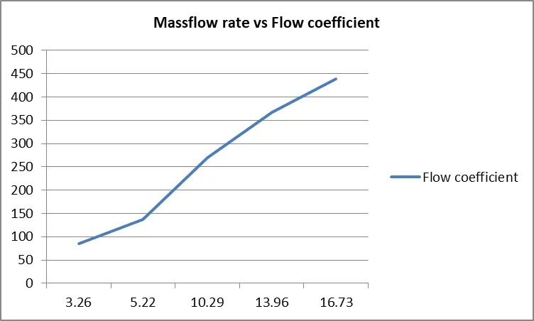
- In the graph of Mass flow rate vs Flow coefficient, the flow coefficient increases linearly with the mass flow rate.
References: