Week 4 - CHT Analysis on Exhaust port
CHT Analysis on Exhaust port
Aim:
To perform Conjugate Heat Transfer analysis on Exhaust port.
Introduction:
Conjugate heat transfer corresponds with the combination of heat transfer in solids and heat transfer in fluids. In solids, conduction often dominates whereas in fluids, convection usually dominates. Conjugate heat transfer includes both conduction and convection.
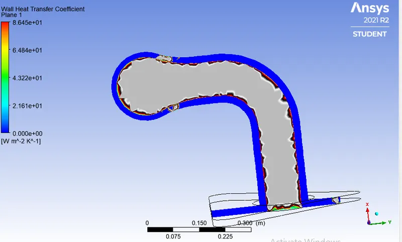
As the hot air passes through the exhaust port it is obvious that it will heat the inner exhaust wall by exchange of energies between the hot air and wall, the exchange of temperature depends on the wall heat transfer coefficient, and in this simulation, we are supposed to examine the wall heat transfer coefficient and hotspots produce on the wall due to flow of hot air.
Some of the applications include, efficiently combining heat transfer in fluids and solids is the key to designing effective coolers, heaters, or heat exchangers. The fluid usually plays the role of energy carrier on large distances. Forced convection is the most common way to achieve a high heat transfer rate. In some applications, the performances are further improved by combining convection with phase change (for example liquid water to vapor phase change). Even so, solids are also needed, in particular to separate fluids in a heat exchanger so that fluids exchange energy without being mixed. [1]
Y Plus:
It's important that your mesh near the wall is properly sized to ensure accurate simulation of the flowfield. Hence Y helps in computing the height of the 1st mesh cell of the wall for proper tracking of the boundary layer near the wall.
PROCEDURE:
Pre-Processing:
- Geometry
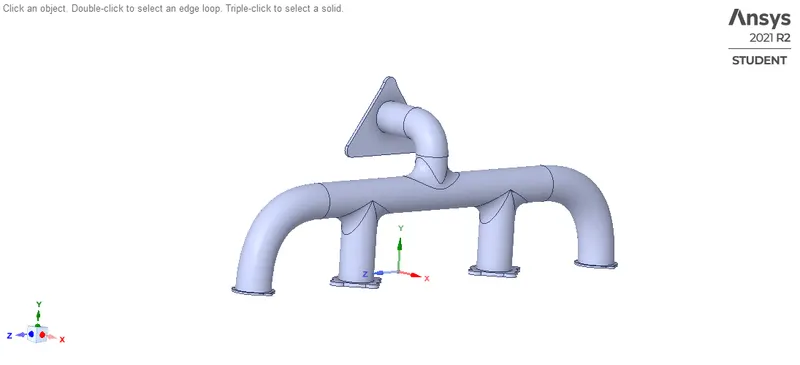
Fluid volume extraction
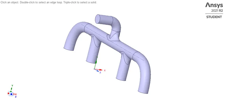
Solid volume extraction
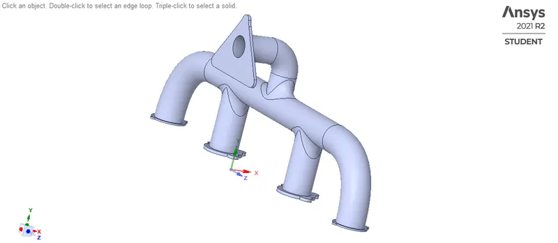
Interference check

Share topology
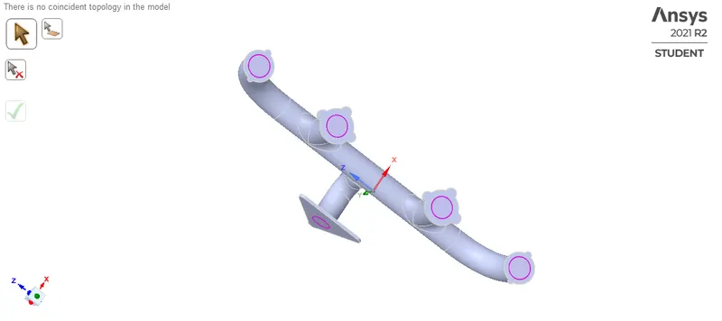
- Mesh
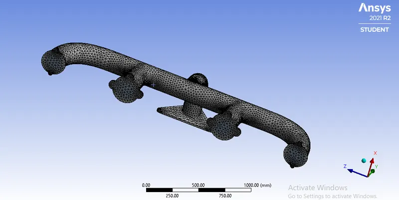
Baseline mesh
Element: 136056
Elements size: 150mm
Setup
Steady:
General: Pressure based, absolute, Steady state
Model: K-omega>SST
Material: fluid, (air)
Density = 1.225 kg/
Cp = 1006.43 J/kg.k
Viscosity = 0.00001789 kg/ms
Solid, (aluminium)
Density = 2719 kg/
Cp = 871 J/kg.k
Cell zone: fff_fluidvolume
Fff_solidvolume
Boundary condition: inlet-velocity= 5m/s
Outlet = 0 Pa (1 atm)
Wall = no-slip condition
Temperature = 700K
Method: Simple
Definitions: velocity contour, temperature contour and wall heat transfer coefficient.
Initialization: Hybrid initialization
Run-calculation: 600-iterations
Results
Post-Processing
Steady
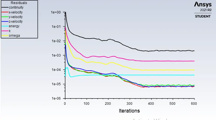
Residual plot
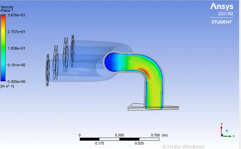
Velocity Contour
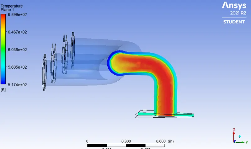
Temperature contour
Wall heat transfer coefficient
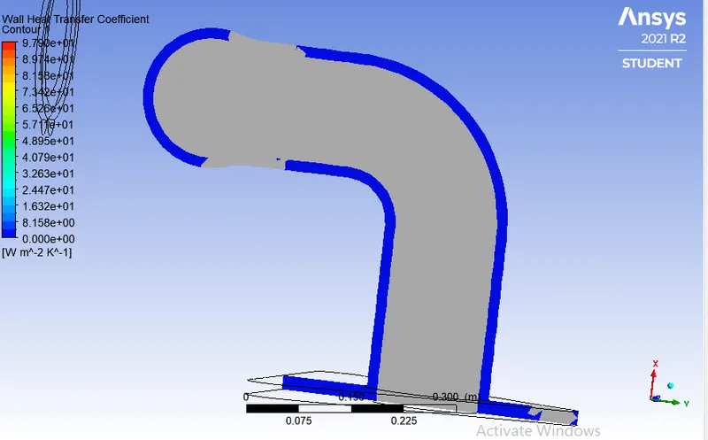
Final simulation
Refined meshing
Element size: 50mm
Elements: 16982
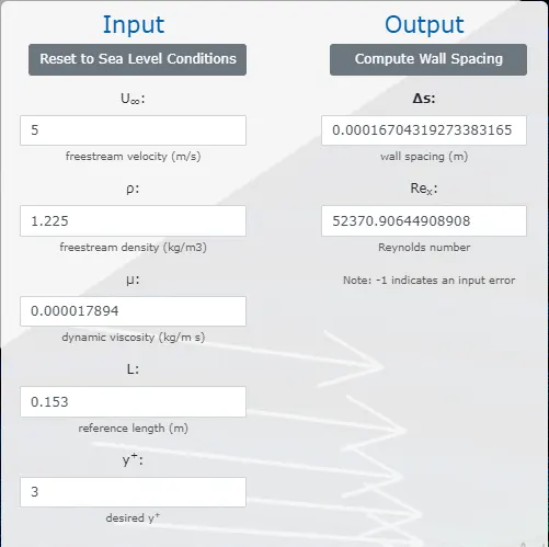
Y-plus
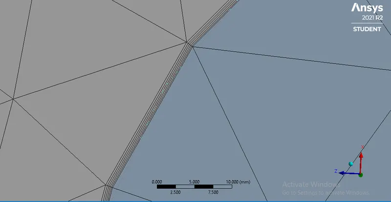
Inflation layer
Inflation layer height (1st layer): 0.16 mm
Total thickness: 1.135mm
Maximum layers: 5
Growth rate: 1.2
Pre-processing
Steady:
General: Pressure based, absolute, Steady state
Model: K-omega>SST
Material: fluid, (air)
Density = 1.225 kg/
Cp = 1006.43 J/kg.k
Viscosity = 0.00001789 kg/ms
Solid, (aluminium)
Density = 2719 kg/
Cp = 871 J/kg.k
Cell zone: fff_fluidvolume
Fff_solidvolume
Boundary condition: inlet-velocity= 5m/s
Outlet = 0 Pa (1 atm)
Wall = no-slip condition
Temperature = 700K
Method: Simple
Definitions: velocity contour, temperature contour and wall heat transfer coefficient.
Initialization: Hybrid initialization
Run-calculation: 600-iterations
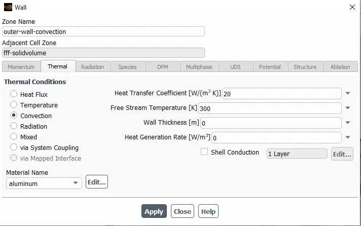
Outer wall convection
Results
Post-Processing
Steady
Residual plot
Velocity contour
Temperature contour
Wall heat transfer coefficient
Conclusion
- We selected K-omega model for our simulation as we are dealing with the results near the wall.
- Baseline simulation was done just to get a rough idea about the results that we were looking at, and the baseline simulation was unable to capture the wall heat transfer coefficient where-as velocity and temperature contours were perfectly observed.
- After adding inflation layer by precisely calculating the first layer thickness by taking Y+ as 3 we observed wall heat transfer coefficient very clearly near the inner wall of the exhaust.
- After closely observing the temperature and velocity contour the hotspot region was observed at the neck of the outlet, this was because of the higher velocity at the neck due to conservation of mass and which resulted in higher heat transfer coefficient at the neck which means higher heat transfer rate at neck.
Analytical method for calculating HTC
Nusselt number:
a dimensionless parameter used in calculations of heat transfer between a moving fluid and a solid body.
Prandtl number:
In heat transfer problems, the Prandtl number controls the relative thickness of the momentum and thermal boundary layers. When Pr is small, it means that the heat diffuses quickly compared to the velocity
`Nu=0.23(Re^0.8 ) (Pr)^n`
where,
`Pr=(Cp μ)/k`
`Re=(ρUL)/μ`
References: