Week 3 - External flow simulation over an Ahmed body.
External flow simulation over an Ahmed body
Aim:
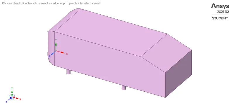
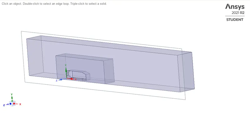
The geometry which is provided with the challenge needs a modification which you should be able to do at this stage of a course. You need to use the 'split body' command in SpaceClaim to perform the operation and then you can use the symmetry boundary condition in fluent to perform the simulation.
Run the simulation for the velocity of 25 m/sec with the default air properties in fluent.
Introduction:
Ahmed Body:
The Ahmed body is a generic car body (a simplified vehicle model). The airflow around the Ahmed body captures the essential flow features around an automobile and was first defined and characterized in the experimental work of Ahmed. Although it has a very simple shape, Ahmed body allows us to capture characteristic features that are relevant to bodies in the automobile industry.
This model is also used to describe the turbulent flow field around a car-like geometry. Once the numerical model invalidated, it is used to design new models of the car.
Y Plus:
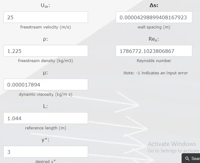
It's important that your mesh near the wall is properly sized to ensure accurate simulation of the flowfield. Hence Y helps in computing the height of the 1st mesh cell of the wall for proper tracking of the boundary layer near the wall.
PROCEDURE:
Pre-Processing:
Geometry
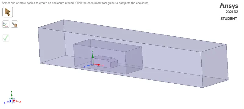
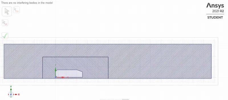
Enclosed in wind-tunnel
Split-body command
Overlapping
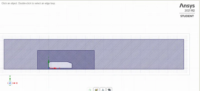
Interference check:
Mesh
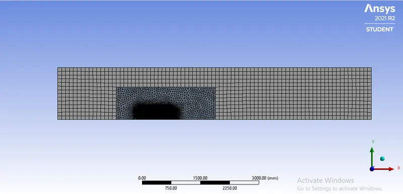
Cell count: 4.27025
Method: multizone
Outer enclosure element size: 100mm
Inner enclosure element size: 35mm
Face (car-wall) element size: 10mm
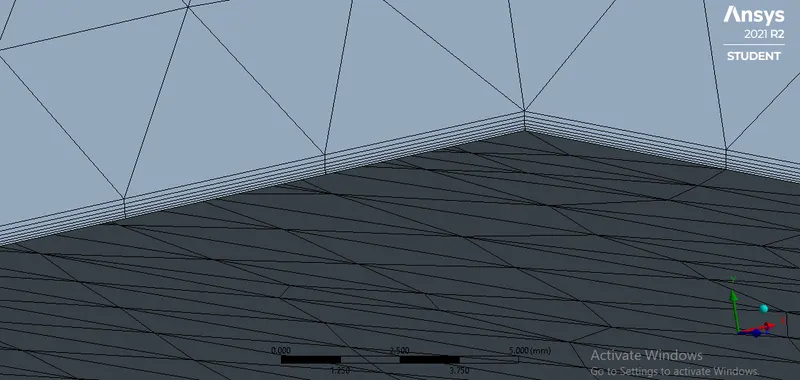
Inflation layers:
Inflation layer height (1st layer): 0.042mm
Total thickness: 0.4169mm
Maximum layers: 6
Growth rate: 1.2
Y-plus:
Inflation layer thickness:
Setup
Steady:
General: Pressure based, absolute, Steady state
Model: K-omega>SST
Material: Default (air)
Cell zone: enclosure_enclosure
Boundary condition: inlet-velocity= 25m/s
Outlet = 0 Pa (1 atm)
Wall = no-slip condition
Method: Simple
Definitions: lift, drag, velocity-contour, pressure-contour
Initialization: Hybrid initialization
Run-calculation: 500-iterations
Results
Post-Processing
Steady
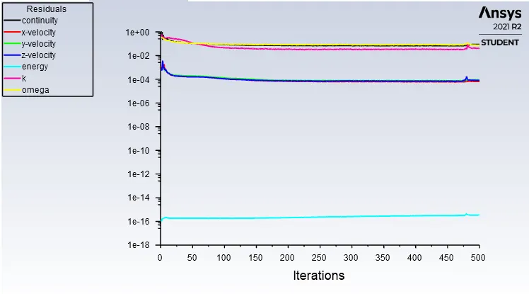
Residual plot
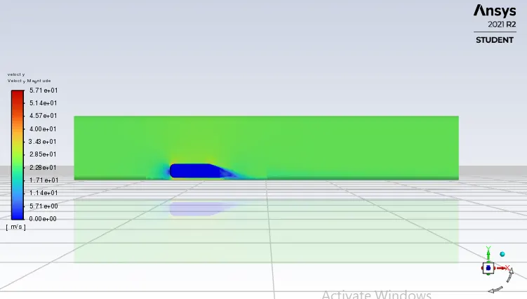
Velocity Contour
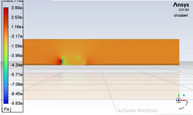
Pressure contour
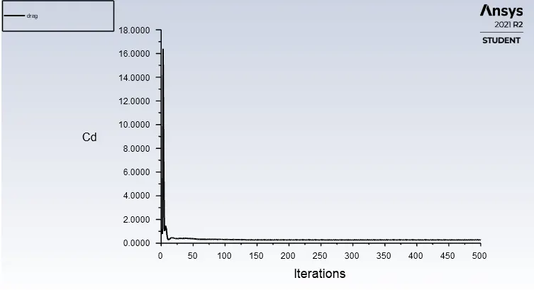
Coefficient of drag:
Coefficient of lift
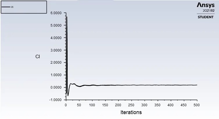
- Coefficient of drag was observed to be 29,
- Coefficient of lift was observed to be 2161
Grid independence test:
|
|
1 |
2 |
3 |
|
Outer-enclosure (mm) |
100 |
100 |
100 |
|
Inner-enclosure (mm) |
50 |
40 |
35 |
|
Face (car-wall) (mm) |
10 |
10 |
10 |
|
Inflation layer (1st layer thickness) (mm) |
0.042 |
0.042 |
0.042 |
|
No of elements |
3.7e5 |
4.1e5 |
4.7e5 |
|
|
|||
|
Cd |
0.26 |
0.27 |
0.29 |
|
Cl |
0.19 |
1.95 |
0.23 |
Conclusion
As earlier explained Ahmed body is approximate simulation for external flow over vehicle (car), firstly it was observed that as we refine the mesh with minimum possible element size and by properly selecting the inflation layer height out output got more precise as you can see in the above table. After close observing the velocity and pressure contour it was observed that there was negative pressure observed in the wake region due to vortex generated behind the bluff body. The stagnation point was observed on the nose part of Ahmed body due air accumulation due to high air pressure.