Week 9 - Parametric study on Gate valve.
AIM: To perform a parametric study on the gate valve simulation by setting the opening from 10% to 80%.
OBJECTIVE:
- To obtain the mass flow rates at the outlet for each design point.
- Calculating the flow coefficient and flow factor for each opening and plot the graph.
- Discuss the results of the mass flow rate and flow coefficient.
INTRODUCTION
- The gate valve has wide range of application starting from household to industria services.
- These are used when minimum pressure loss is needed.
- Gate valve opens in the perpendicular direction of the flow of fluid.
- It is only used to stop or restart the flow of fluid.
- Used in fluid pipelines to control the flow of fluid.
- As the valve has to turn multiple times to go from open to closed position, this slow process also prevents watter hammer effects.
- There are three types of gate valves depends on type of disc, type of body bonnet joint and type of stem movement.
- Common materials used : Grey cast iron-household pipe fittings
Nodular graphite cast iron, stainless steel casting, Bronze- for low pressure services.
SOLVING AND MODELLING APPROACH
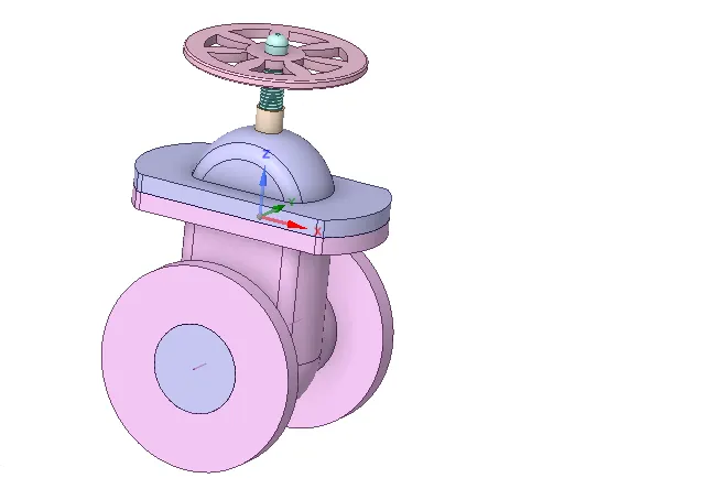
Fig.1 Gate valve
- The geometry shown here is the gate valve and the parts attached here are bonnet, hand wheel, bottom and gate disc respectively.
- The hand wheel is steered for regulating the disc motion i.e, the valve lift takes place accordingly.
- The bonnet works like casing and coering the fluid volume.
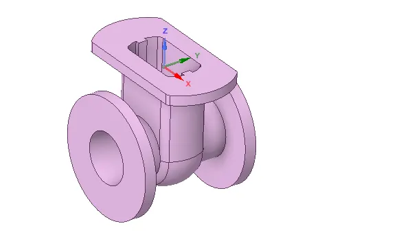
Fig.2 Bottom part of gate valve
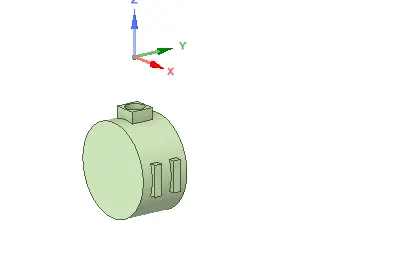
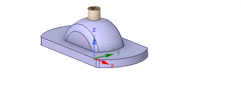
Fig.3 gate disc Fig.4 Bonnet
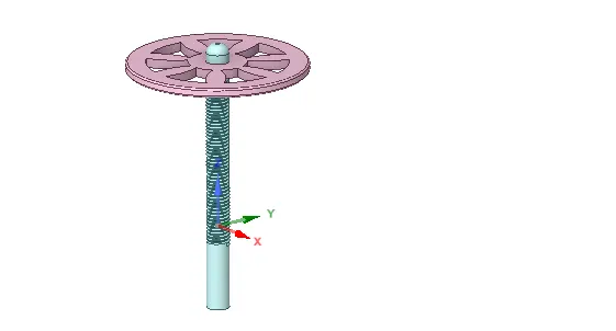
Fig.5 Hand wheel
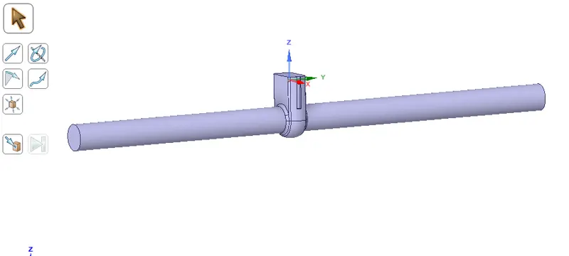
Fig.6 Geometry preparation
- Here the inlet and outlet are extruded using pull command and the length is 800mm.
- Then suppress all other parts for physics. As we are interested in only valve lift and fluid flow.
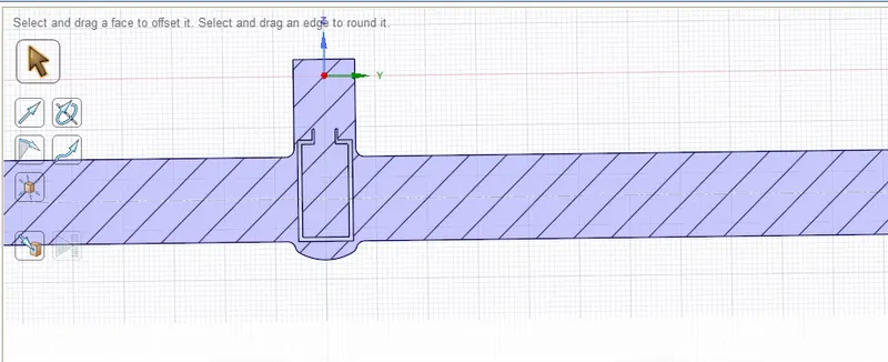
Fig.7 Cross-section (10mm valve lift)
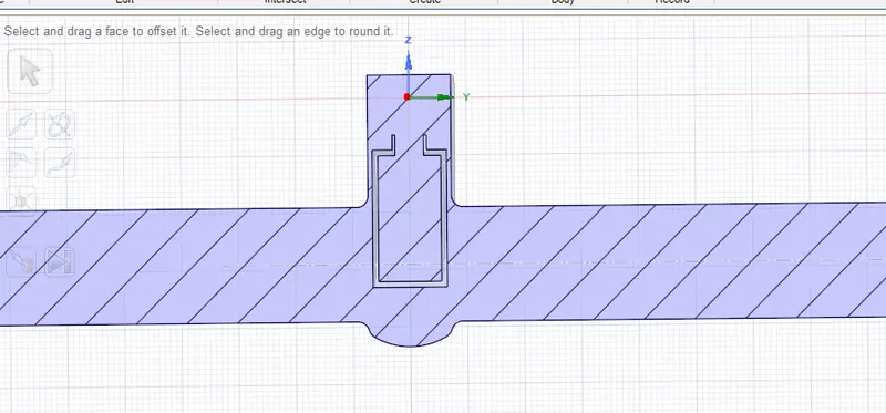
Fig.8 Cross-section (40mm valve lift)
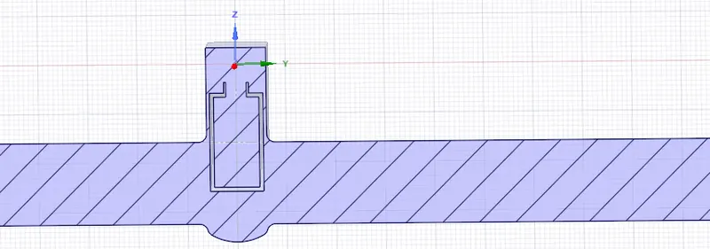
Fig.9 Cross-section (50mm valve lift)
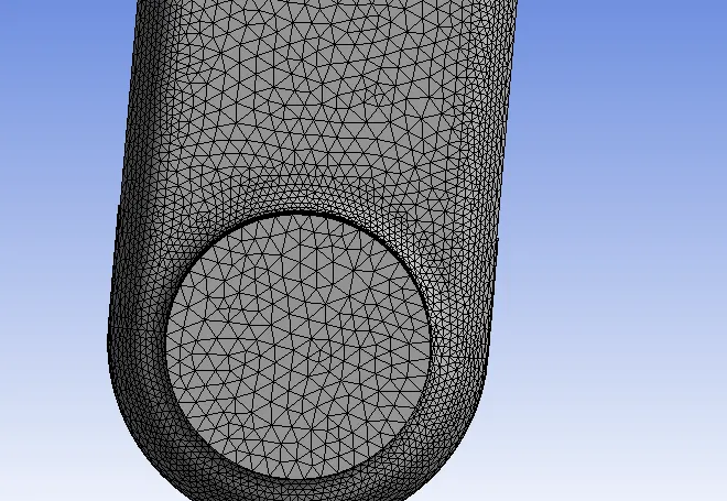
Fig.10 Mesh (50mm valve lift)
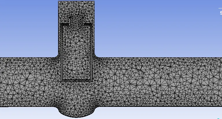
Fig.11 mesh (50mm valve lift)
PRE-PROCESSING AND SOLVER SETTING
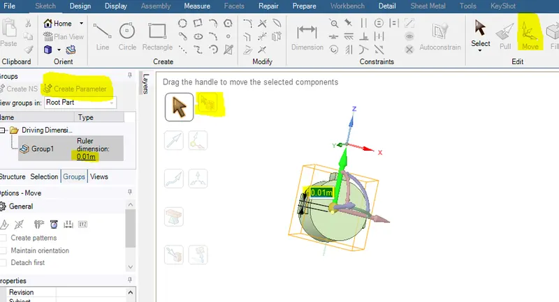
Fig.12 input parameter(valve lift) setup
- As per our requirement we can provide the lift distance and the geometry modifies in an accordance with that the mesh setting .
- For parametric study of gate valve , we can provide different values in parameter set design table.
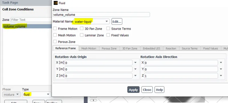
Fig.13 setting material (fluid:water) in cell zone
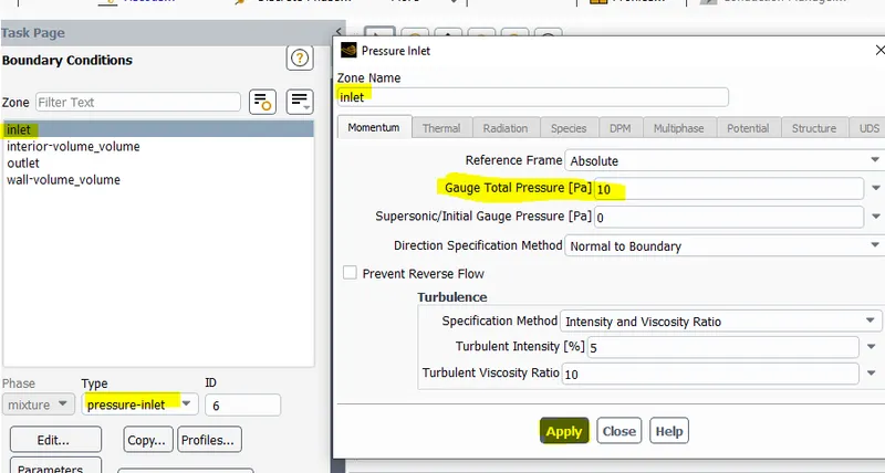
Fig.14 setting up inlet pressure boundary
Case set up
Geometry - pressure based steady solver
Model : k-epsilon Realizable with scalable wall function
Material: Fluid-water(liquid)
Boundary condition- Inlet pressure (10 Pa gauge)
Initialization - Standard initialization
Report Defination- Mass flow rate.
RESULTS
CASE-1
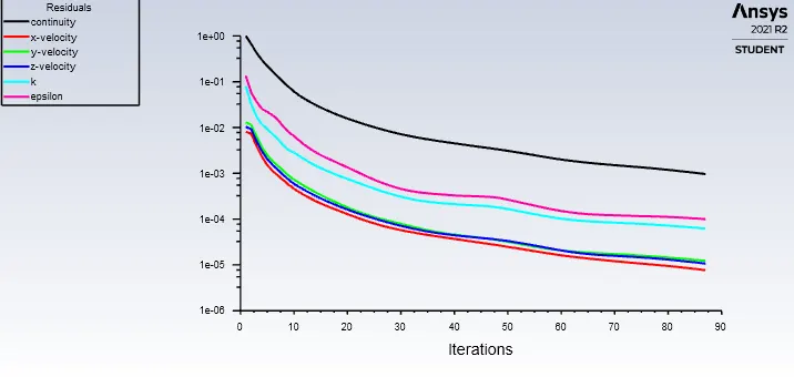
Fig.15 Residual vs iteration
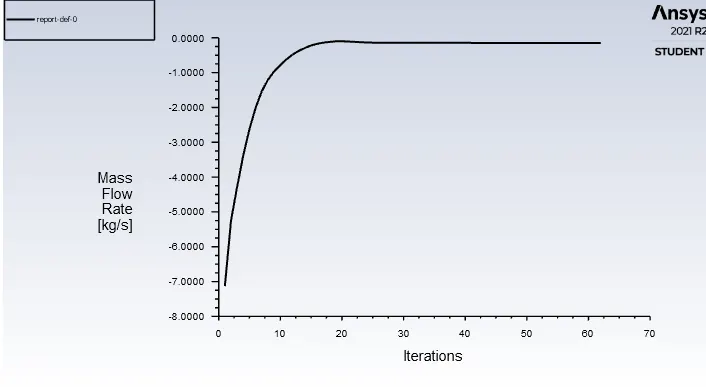
Fig.16 Mass flow rate Vs iteration
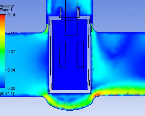
Fig.17 Velocity plane for 10mm valve lift
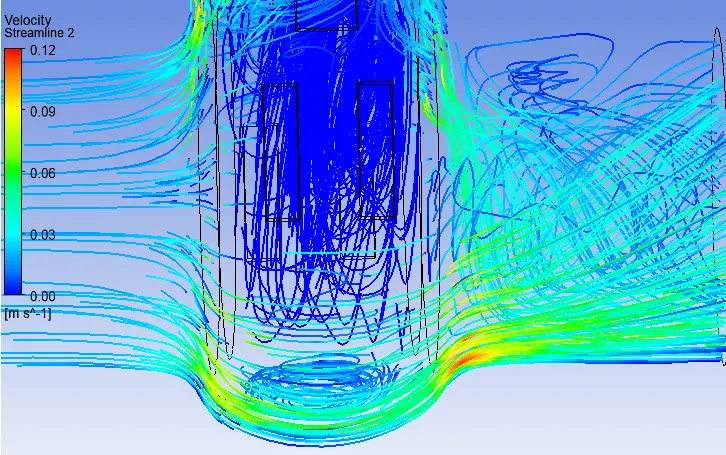
Fig.18 Velocity Streamline for 10mm valve lift
CASE-2
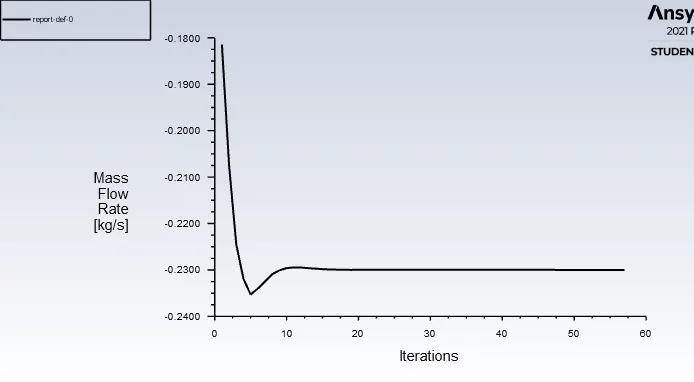
Fig.19 Residual vs iteration
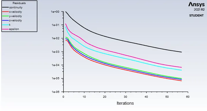
Fig.20 Mass flow rate Vs iteration
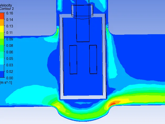
Fig.21 Velocity plane for 20mm valve lift
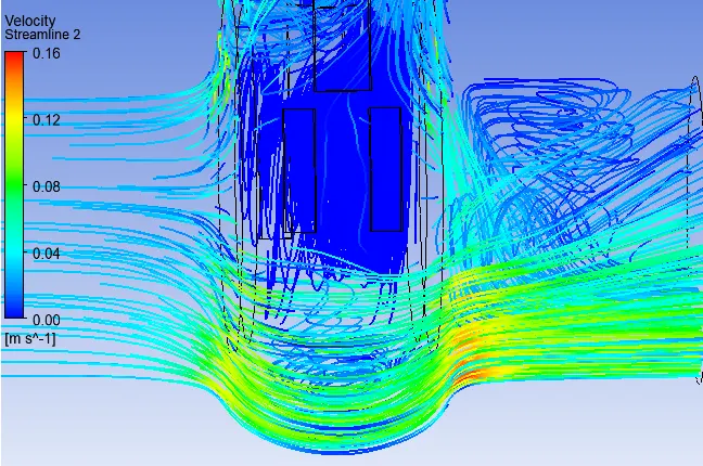
Fig.22 Velocity Streamline for 20mm valve lift
CASE-3
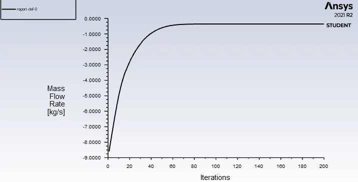
Fig.23 Mass flow rate Vs iteration
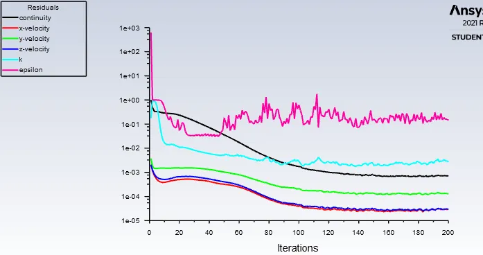
Fig.24 Residual vs iteration
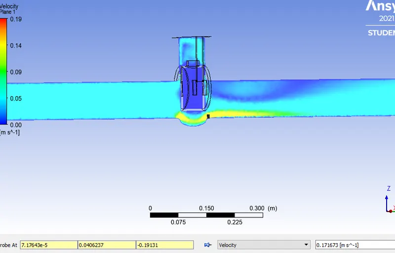
Fig.25 velocity plane for 30mm valve lift
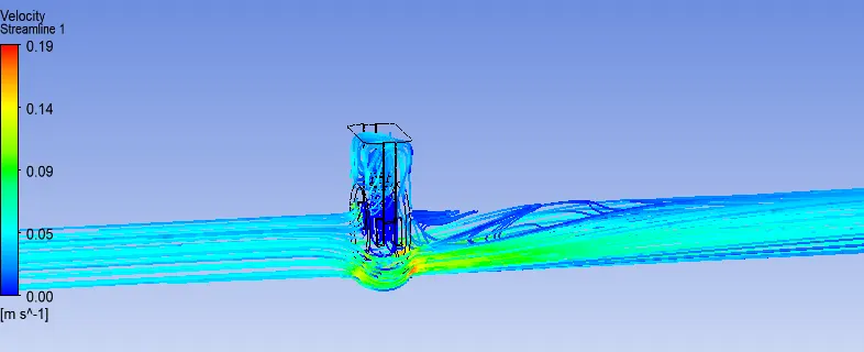
Fig.26 Velocity streamline for 30mm valve lift
CASE-4
- Mesh element size : 443447
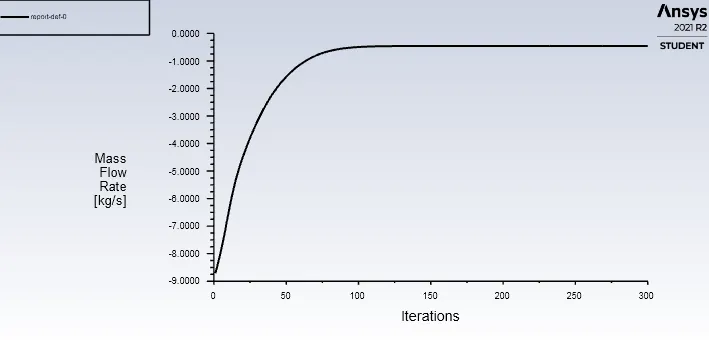
Fig.27 Mass flow rate Vs iteration
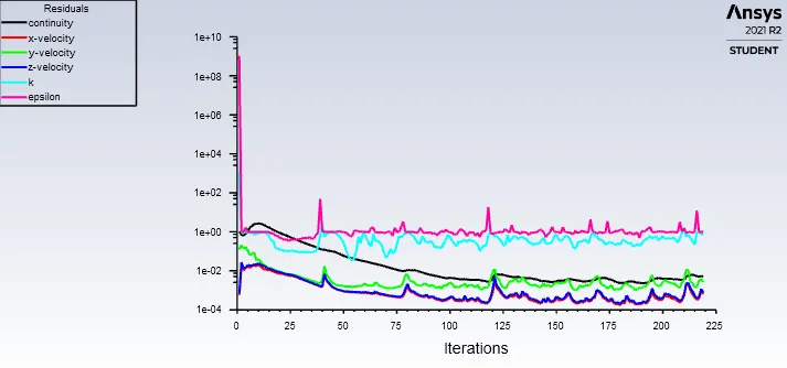
Fig.28 Residual vs iteration
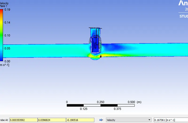
Fig.29 velocity plane for 40mm valve lift
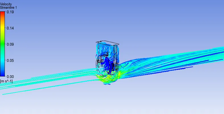
Fig.30 Velocity streamline for 40mm valve lift
CASE-5
- Mesh element size: 448440
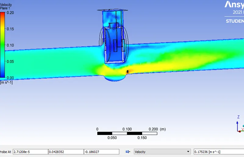
Fig.31 velocity plane for 50mm valve lift
- The probe here gives the velocity magnitude near the balve passage is 0.17m/s. It is less than the lower valve lift velocity magnitude.
- As the area of flow passage increases ,according to mass conservative principle the velocity decreases.This might be another reason for decrease in discharge coefficient with increase valve lift.
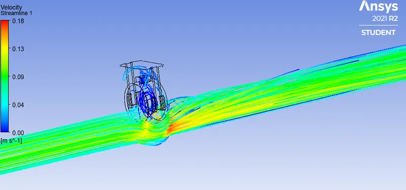
Fig.32 Velocity streamline for 50mm valve lift
CASE-6
- Mesh element size: 442373
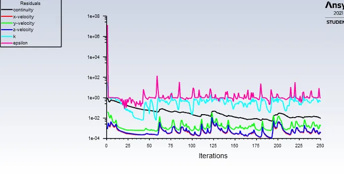
Fig.33 Residual vs iteration
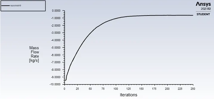
Fig.34 Mass flow rate Vs iteration
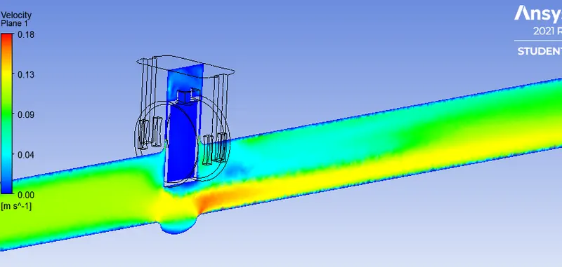
Fig.35 velocity plane for 60mm valve lift
Fig.36 Velocity streamline for 60mm valve lift
Flow- coefficient and Flow- factor
- Generally Cv is defined as flow capacity of devices.So,Cv is designing factor which relates head drop or pressure drop across the valve with the flow rate(Q).
- Flow coef. =`Q*sqrt((SG)/(Deltap)` where Q= volumetric flow rate in gallons per minute,
- Flow-Factor = `Q*sqrt((SG)/(Deltap))` where Q= volumetric flow rate in `(m^3/(hr))`
`Deltap`=pressure drop across valve or inlet and outlet
SG=specific gravity.
- For calulating the pressure drop for flow -coefficient the unit is in PSI
- For calculating pressure drop for flow factor,the unit is in bar
Significance of flow coefficient
- We can quickly compare different brands of valves and their flow capacities.
- Quickly understand how the valve have an effect on the pressure in the system.
- selecting valve that is right size for the application.
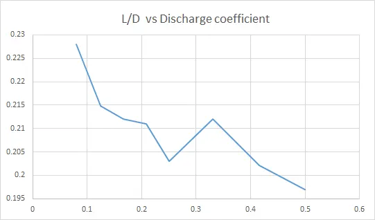
Fig.37 lift/diameter of disc( non-dimensionless number) vs discharge coefficient
- At higher lifts Cd decreases linearly with increasing valve lift as the available area is not efficiently used as the flow is separated near the gate valve wall.
- Fluid coming from upstream strikes at valve gate and can not follow thecircumference path of gate valve.Due to inertia ,it breaks away from the surface and then re-attach to form free-jet.
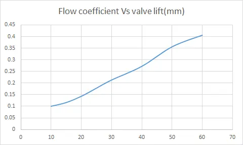
Fig.38
- From the graph, it is shown that the flow -coefficient varies almost linearly with valve lift.
- As the lift increases ,the valve impart less resistance or obstruction to fluid flow.
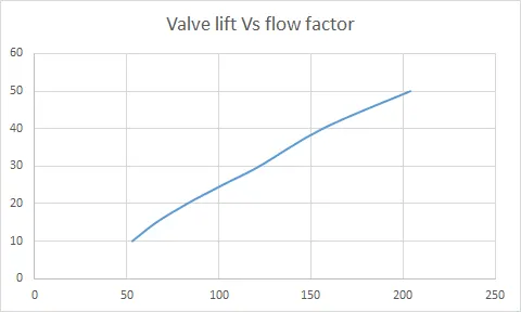
Fig.39
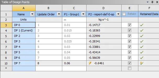
Fig.40
- Here the mass flow rate increases as the valve lift increases.So the gate disc designed satisfies the requirement for the application .
- At higher valve lift it is found that near the valve opening the flow is tansitioned from laminar to turbulent.Their is intermixing of fluid layers from two sides of gate disc.
| Valve lift(mm) | Mass flow rate(kg/s) | Vol. flowrate(gpm) | Flow-coeff. | Flow-factor |
Discharge Coeff. |
| 10 | 0.147 | 2.33 | 61.188 | 52.9 | 0.301 |
| 15 | 0.183 | 2.904 | 76.261 | 66 | 0.228 |
| 20 | 0.229 | 3.634 | 95.432 | 82.76 | 0.2148 |
| 25 | 0.2834 | 4.49 | 117.911 | 102.02 | 0.212 |
| 30 | 0.338 | 5.36 | 140.758 | 121.96 | 0.211 |
| 40 | 0.434 | 6.88 | 180.675 | 156.24 | 0.203 |
| 50 | 0.5663 | 8.984 | 235.928 | 203.86 | 0.212 |
| 60 | 0.6461 | 10.255 | 269.30 | 232.59 | 0.202 |
CONCLUSION
- There is increase in mass flow rate and flow coefficient with the increase in valve lift.
- The discharge coeffcient decreases as the valve lift increases.
- We can choose the valve according to our requirement.When there is low head loss is taking place, the flow coeffcient should be high.As we are concerning more about energy required to push the fluid flow.