Week 9 - Parametric study on Gate valve.
Aim:
To perform a parametric study on the gate valve simulation by setting the opening from 10% to 80%.
To obtain the mass flow rates at the outlet for each design point.
To calculate the flow coefficient and flow factor for each opening and plot the graph.
To discuss the results of the mass flow rate and flow coefficient.
Theory:
Gate valve:
A gate valve, also known as a sluice valve, is a valve that opens by lifting a barrier (gate) out of the path of the fluid. Gate valves require very little space along the pipe axis and hardly restrict the flow of fluid when the gate is fully opened. The gate faces can be parallel but are most commonly wedge-shaped (in order to be able to apply pressure on the sealing surface).
Bonnets provide leakproof closure for the valve body. Gate valves may have a screw-in, union, or bolted bonnet. A screw-in bonnet is the simplest, offering a durable, pressure-tight seal. A union bonnet is suitable for applications requiring frequent inspection and cleaning. It also gives the body added strength. A bolted bonnet is used for larger valves and higher pressure applications.
Flow coefficient:
The flow coefficient of a device is a relative measure of its efficiency at allowing fluid flow. It describes the relationship between the pressure drop across an orifice valve or other assembly and the corresponding flow rate.
Mathematically the flow coefficient Cv (or flow-capacity rating of valve) can be expressed as :
`C_v=Q[sqrt((SW)/(DeltaP))]`
where,
Q is the rate of flow (expressed in US gallons per minute),
SG is the specific gravity of the fluid (for water = 1),
`DeltaP` is the pressure drop across the valve (expressed in psi).
Flow factor:
The metric equivalent flow factor (Kv; commonly used everywhere else in the world with the exception of the United States) is calculated using metric units :
`K_v=Q[sqrt((SW)/(DeltaP))]`
where,
Kv is the flow factor (expressed in `(m^{3}/h)`
Q is the flowrate (expressed in cubic metres per hour `({m^{3}/h})`
SG is the specific gravity of the fluid (for water = 1),
`Delta P` is the differential pressure across the device (expressed in [bar]).
`K_v` can be calculated from `C_v` using the equation:
`K_{v}=0.865*C_{v}`
Reynold's number for flow through pipe:
The typical criterion for whether pipe flow is laminar or turbulent is the value of the Reynolds Number. The Reynolds number for pipe flow is defined as Re = DVρ/μ, where D is the pipe diameter, V is the average flow velocity in the pipe, ρ is the density of the flowing fluid and μ is the dynamic viscosity of the flowing fluid. Re is a dimensionless number. Any consistent set of units can be used for D, V, ρ and μ, and will result in Reynolds number being dimensionless. The generally accepted criteria for laminar flow and turbulent flow in terms of Re are as follows:
For Re < 2100, it is laminar flow.
For Re > 4000, it is turbulent flow.
For 2100 < Re < 4000, the flow is in the transition region.
For flow in the transition region, the flow may be either laminar or turbulent, depending upon the nature of the entrance to the pipe and the pipe wall roughness.
BASELINE SETUP: Gate valve - Zero lift configuration
To calculate Reynold's number:
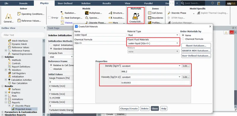
Density & dynamic viscosity of fluid medium (water):
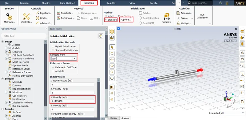
Velocity at inlet:
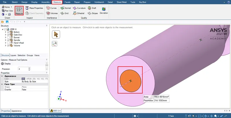
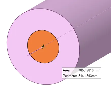
To find diameter from area/perimeter:
Calculation of Reynold's number from the above data to decide the appropriate viscous model.
Data:
Dynamic viscosity of water = `mu_(water)`= 0.001003`(kg)/(ms)`
Density `rho`= 998.2 `(kg)/(m^3)`
`Velocity_(i n l e t)` (V)= 0.1415488 `m/s`
`(Circumference)_(i n l e t)`(C) = 314.1593`mm`
But,
Circumference of circle = `2pir`
`2pir=314.1593mm`
`r=(314.1593mm)/(2pi)`
`r=50mm`
`Diameter (D) = 100mm = 100 *`10^(-3)`m
Reynold's number = `(rhoVD)/(mu)`
Reynold's number = `(998.2*0.1415488*100*10^(-3))/(0.001003)`
Reynold's number = 14087.1398 ~ 14087
Here the flow inside pipe's Reynold's number exceeds the laminar limit (For Re > 4000, it is turbulent flow).
Hence it is best if a turbulent viscous model is chosen for the simulation.
ANSYS SETUP:
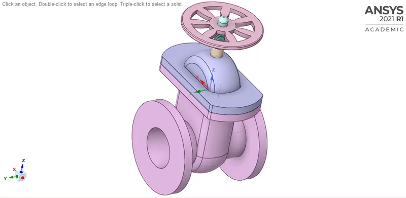
Importing geometry:
File > Open > Navigate to the file location: Select the file.
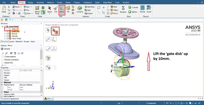
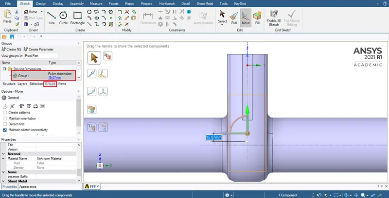
To give gate disk a raise of 10mm lift:
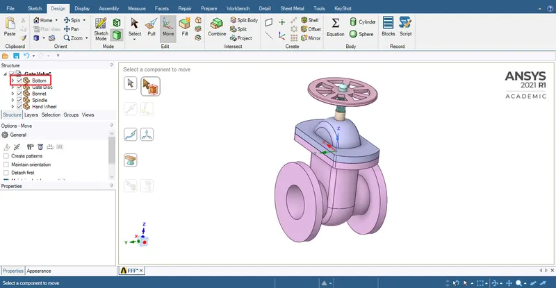
Hide 'Bottom' (under structure):
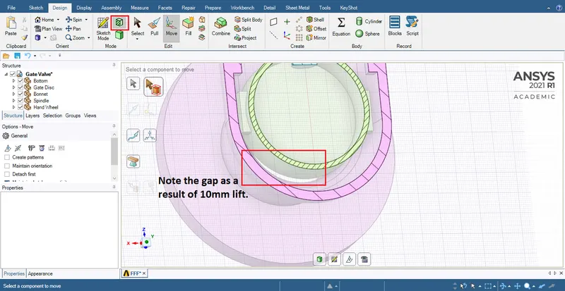
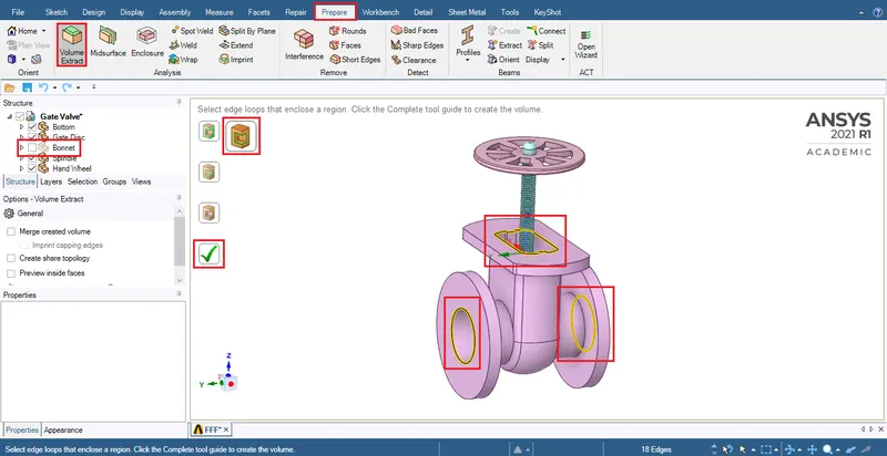
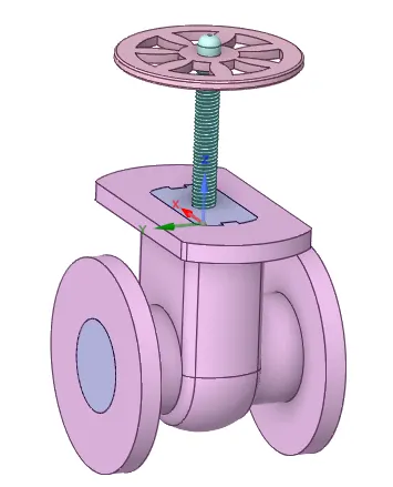
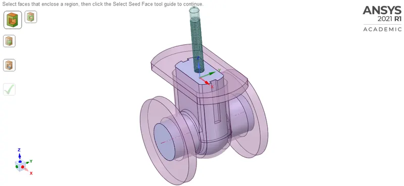
Under 'Design' > Under 'Edit': 'Move' > Click on 'select component' > Move the 'gate disk' by 10mm > Under structure: Hide 'Bottom' > Under 'Prepare' > Under Prepare: (Analysis) 'Volume extract' > Choose 'Select edges' > Select: Inlet, Outlet & Edge hidden under 'Bonnet' (select this edge) > Click the green tick mark to fill the volume.
Fluid volume extension:
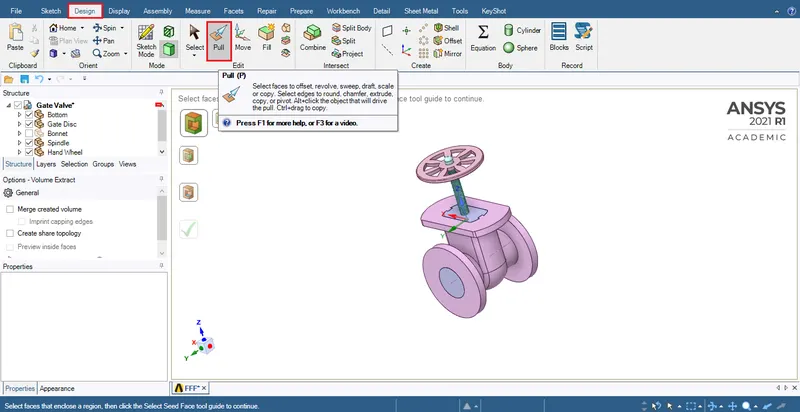
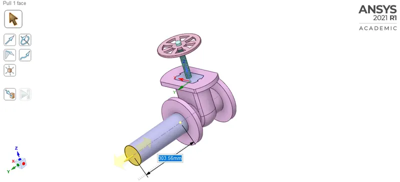
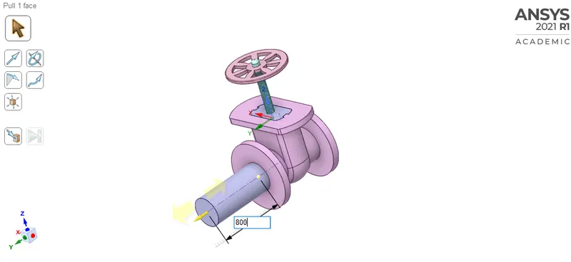
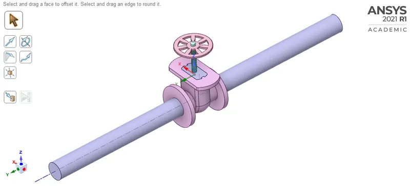
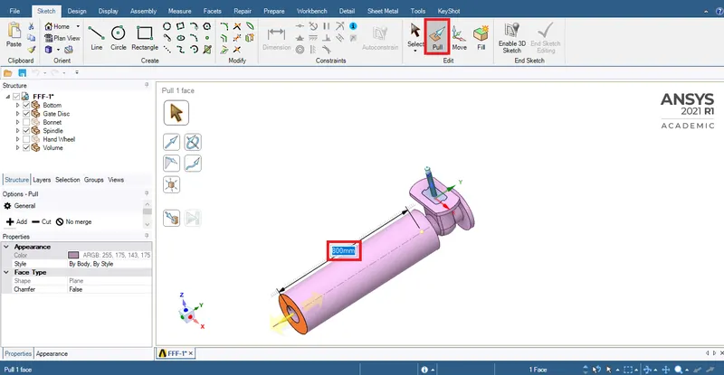
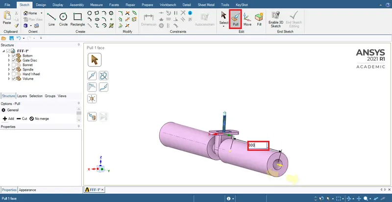
Under 'Design' > Pull > Select the one end of fluid volume and pull it and extend 800mm on both side.
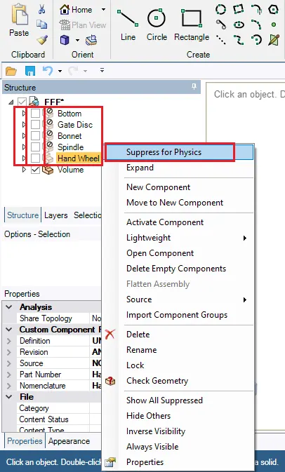
Under 'Structure':
Hide all components except fluid volume.
Right click and hit 'Supress for physics'.
To update a geometry using a parameter, the geometry has to be reset.
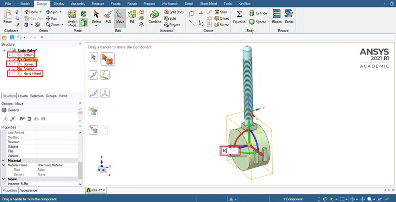
- Hide the Bottom, Bonnet, Handwheel.
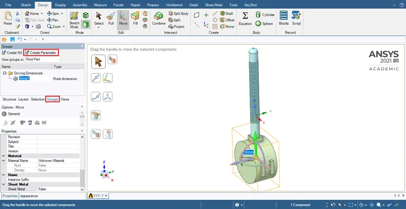
- Under Design: Move > Select the 'gate disk' > Lift the 'gate disk' in positive Y direction > Enter the value of lift required: 10mm.
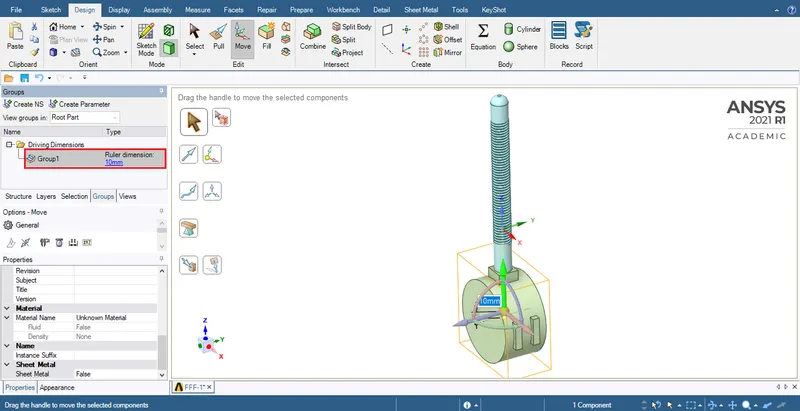
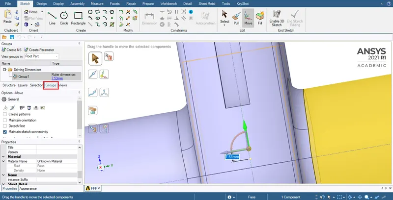
- Under 'structure' (on left hand top corner) > Select 'Groups' > Hit 'Create Parameter' > You can expand the new parameter to view the height of lift, editting or updating the lift to a new possible.
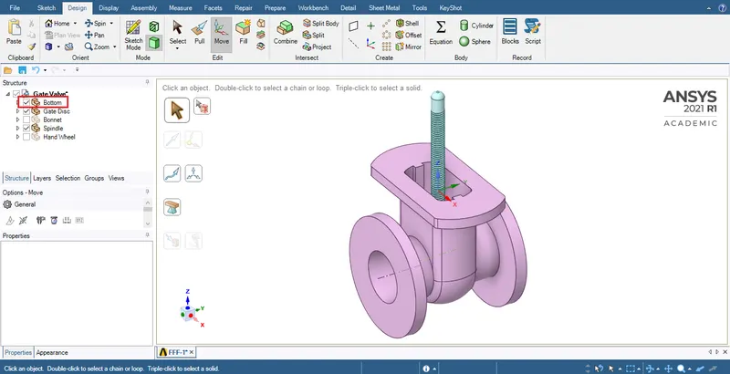
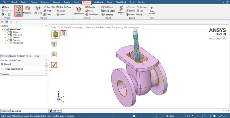
- Under structure: Hide 'Bottom' > Under 'Prepare' > Under Prepare: (Analysis) 'Volume extract' > Choose 'Select edges' > Select: Inlet, Outlet & Edge hidden under 'Bonnet' (select this edge) > Click the green tick mark to fill the volume.
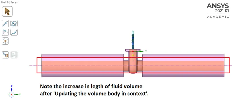
- Under 'sketch' > Pull > Pull the sides of inlet and outlet for 800mm.
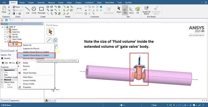
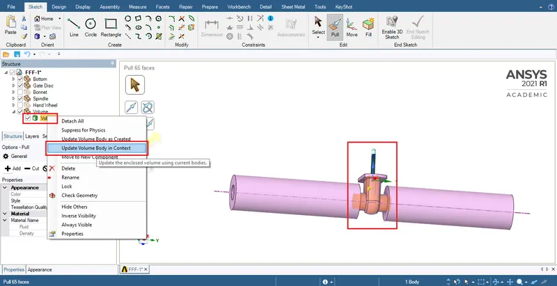
- Under 'Structure' > Expand 'Volume' > Under 'volume': Right click on 'volume' > Select: 'Update volume body in context'.
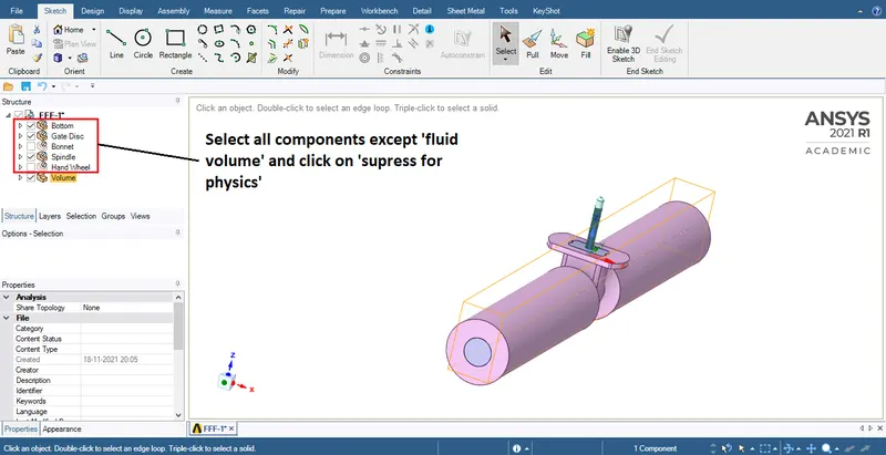
- Under structure: Right click & hit 'Supress for physics' on all components except the 'fluid volume'
Mesh:
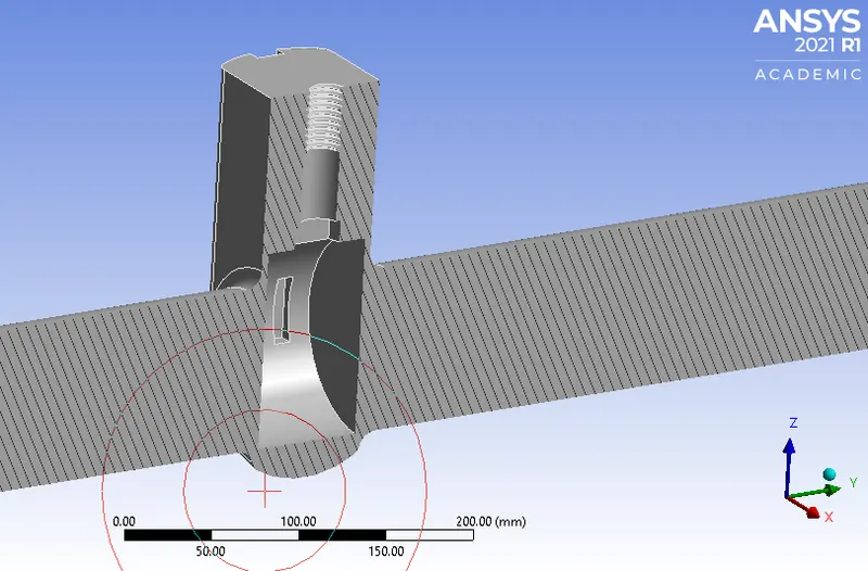
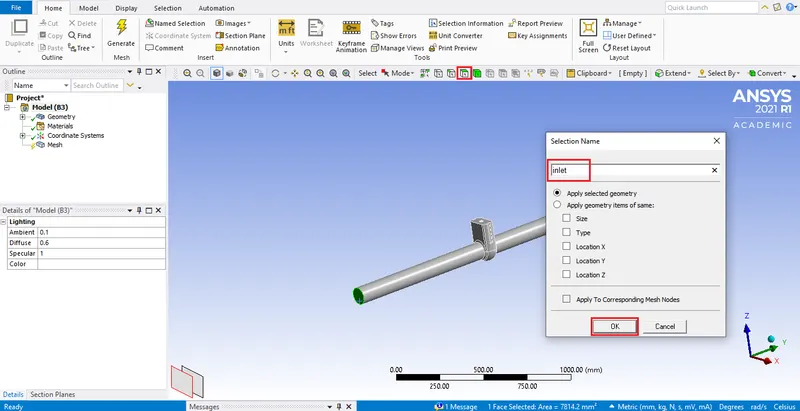
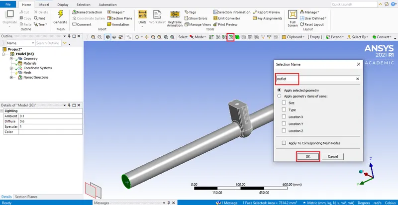
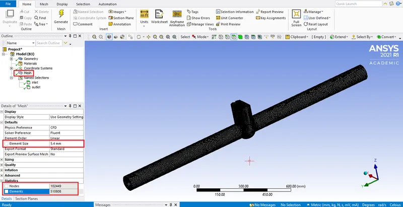
Update the mesh to continue to setup.
Setup:
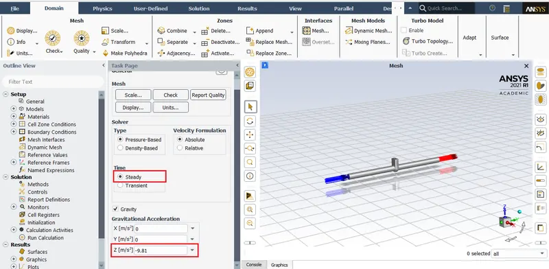
- The gravity acts in the negative z axis and steady state nalysis has been chosen.
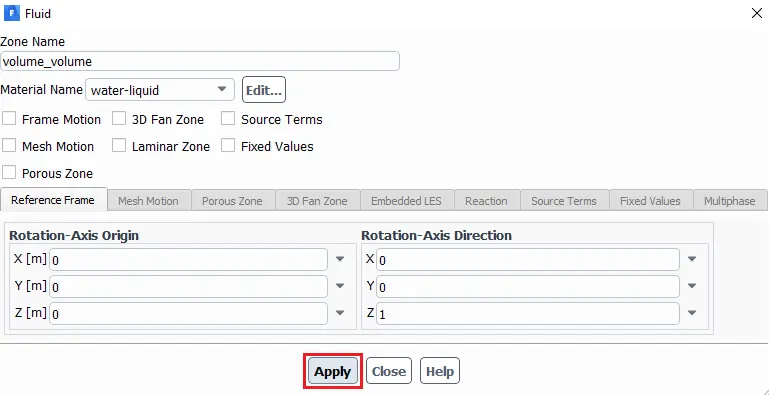
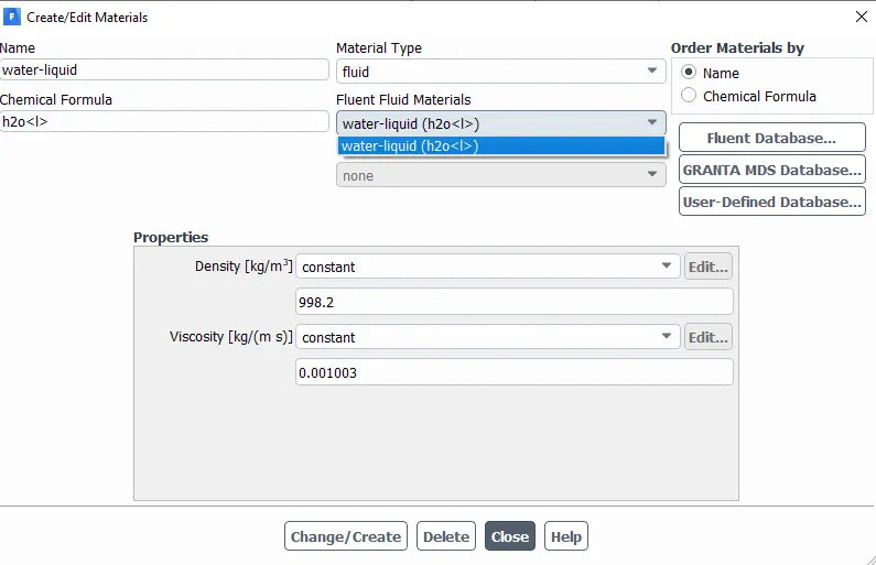
- Fluid medium chosen for this setup is water.
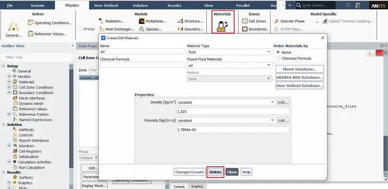
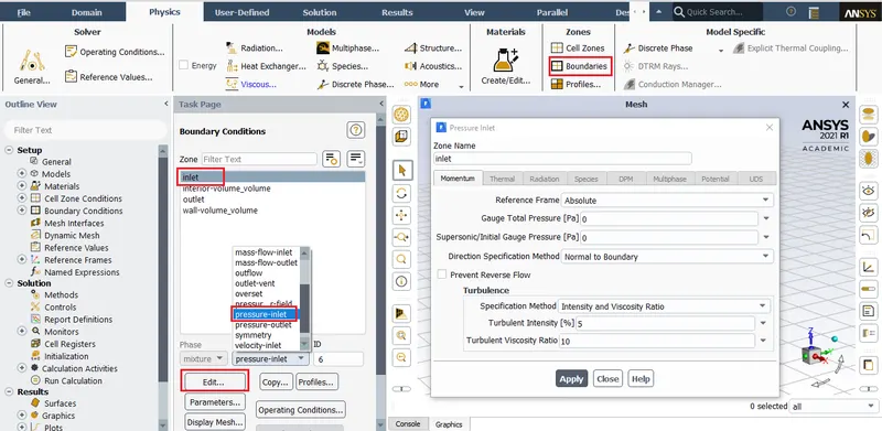
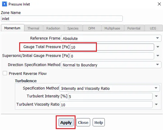
Delete 'air' in materials to avoid confusion. - Choose pressure inlet boundary condition.
Enter inlet pressure = 10 pascal - Choose an appropriate viscous model and create definitions.
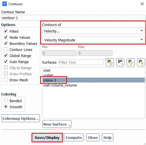
- Create contour plot for velocity using a plane.
- Run calculation.
Materials:
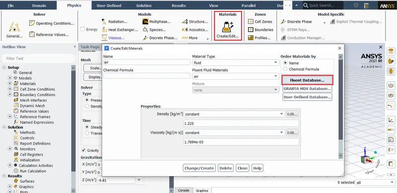
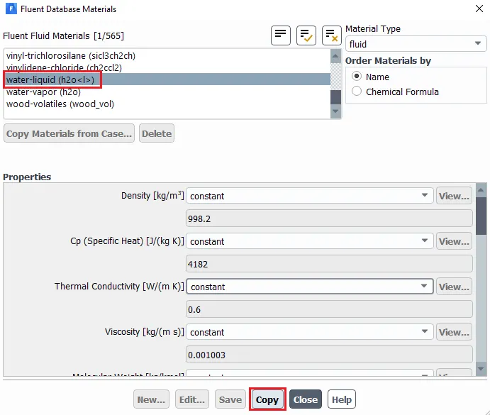
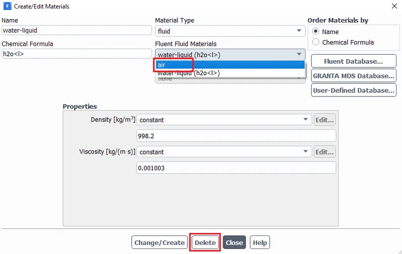
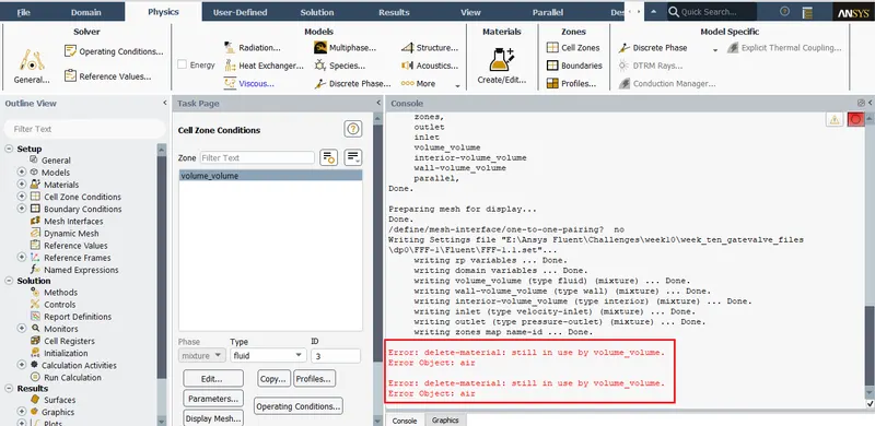
Error encountered while deleting the fluid medium air.
Deleting air as fluid meduim:

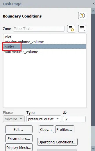
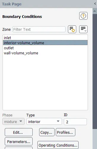
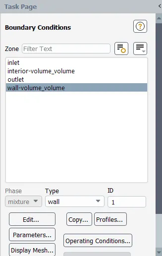
Boundary conditions:
Other boundaries:
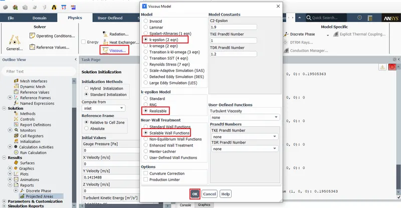
Viscous model:
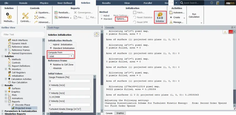
Solution:
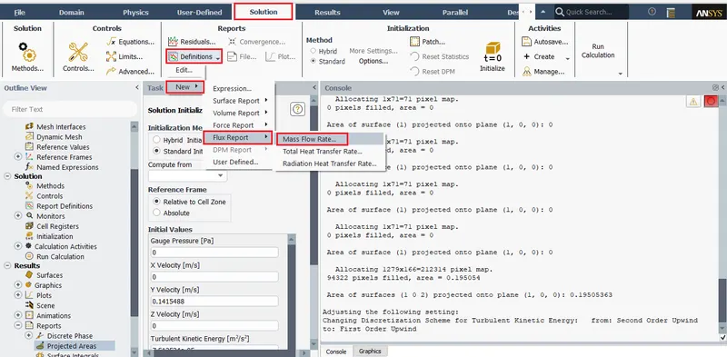
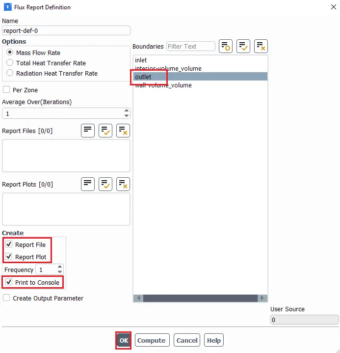
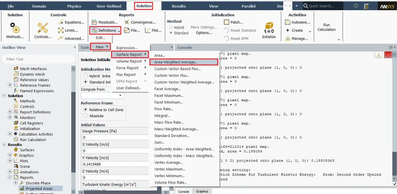
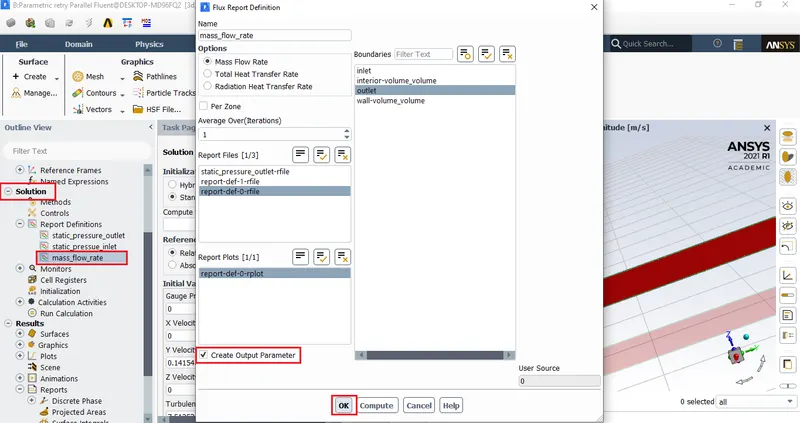
Report generation: Mass flow rate
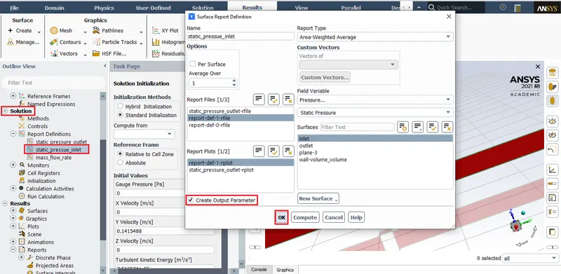
Report generation: Inlet static pressure
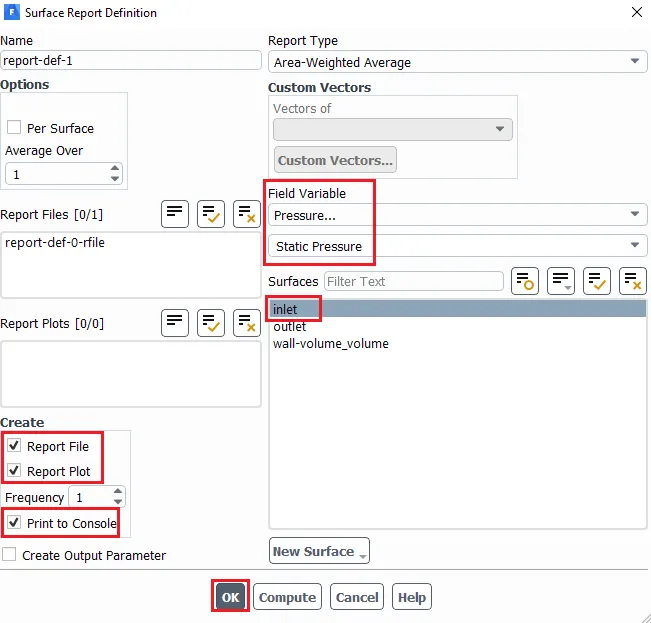
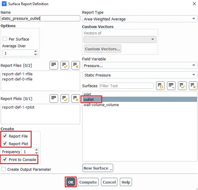
Report generation: Outlet static pressure
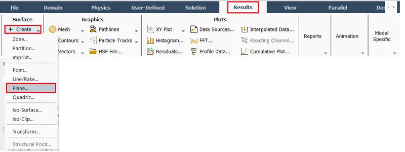
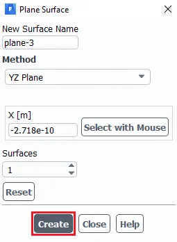
Creating plane:
Creating contour:

To parametrize the reports:
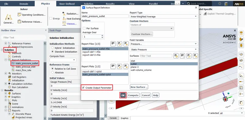
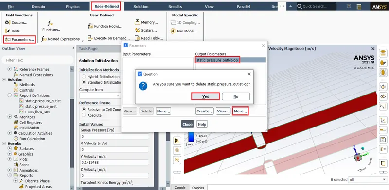
Note: To delete parameters and reports.
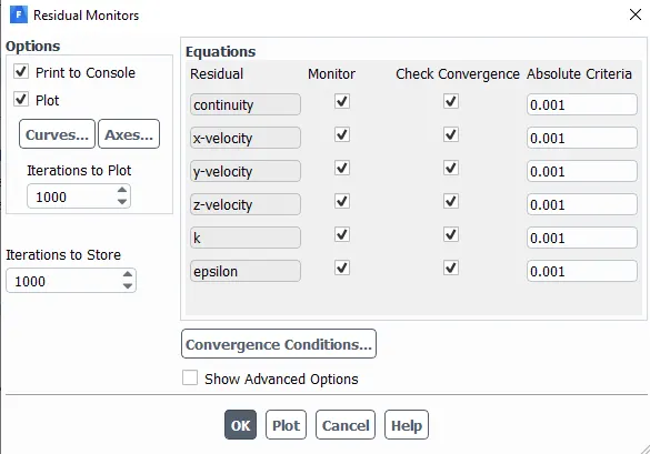
To avoid convergence:
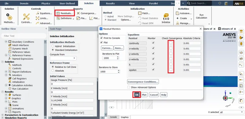
Initializing solution:
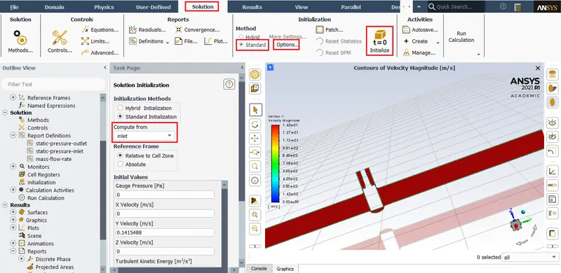
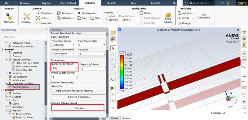
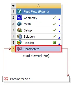
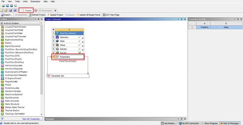
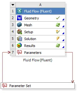
Click on the parameter in the workbench:
To calculate 10% to 80% lift of gate disk the gate height of gate disk at 0 lift must be
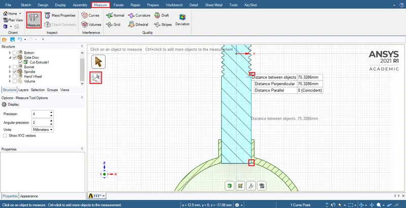
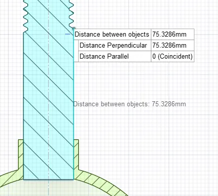
Ansys is considering the spindle to be stationary while the 'Gate disk' moves up and down the spindle shank.
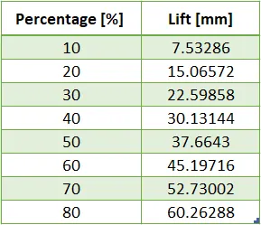
The total liftable length of the spindle is 75.3286mm
So,
The lifts derived from the percentages are as shown below:
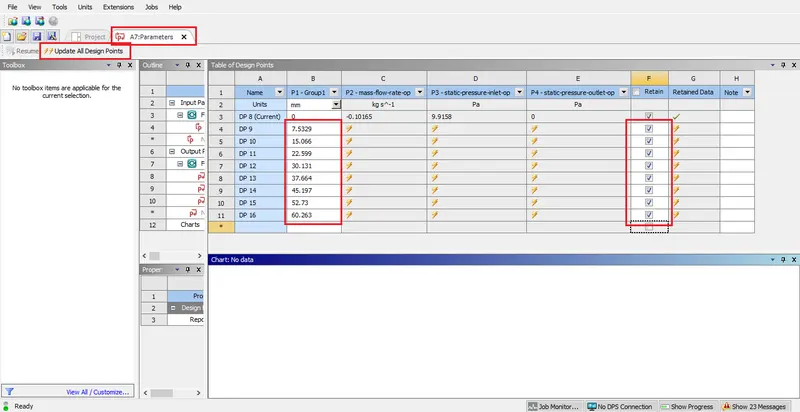
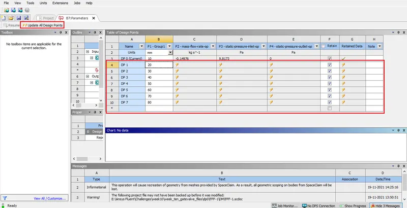
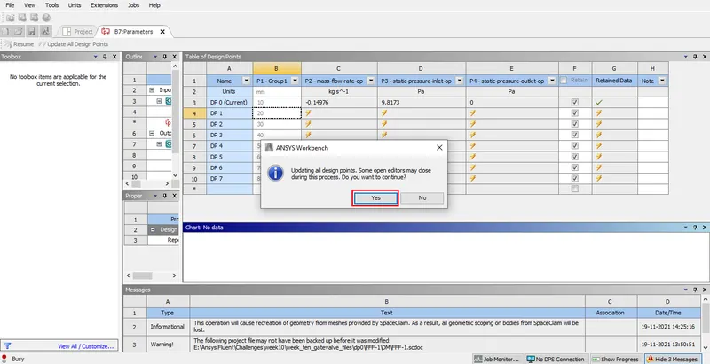
Parametric study:
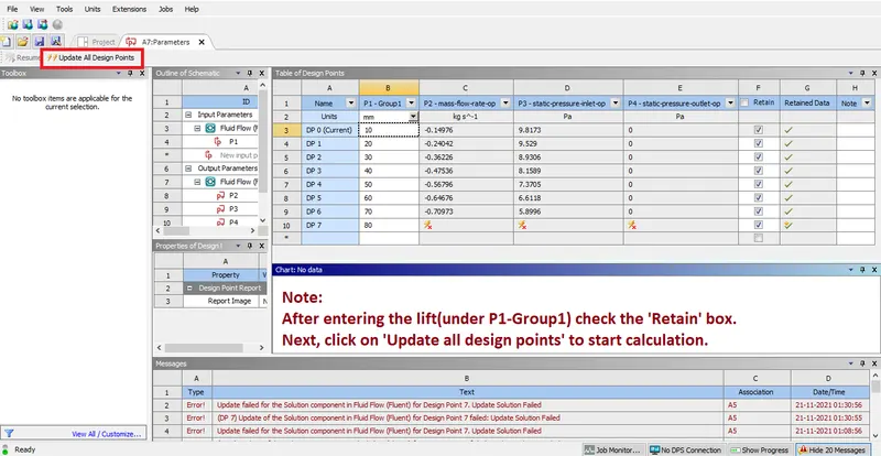
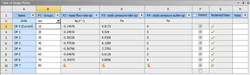
Finished parametric study:
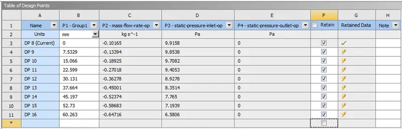
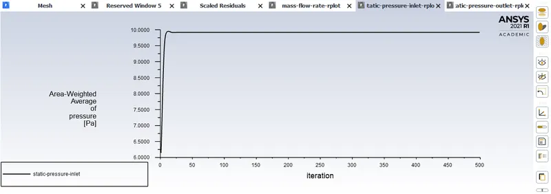
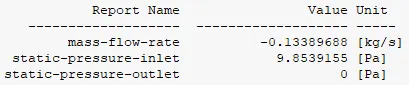
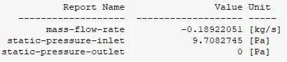
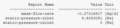
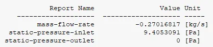
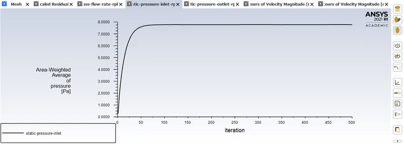
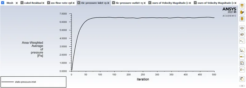
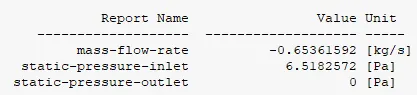
The values of outlet presure is zero beause ansys is calculating guage pressure and hence 'P3-static-pressure-inlet' is the pressure difference between inlet and outlet.
Animation:
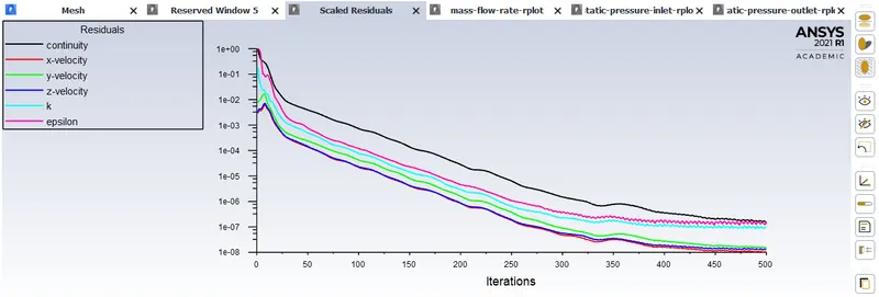
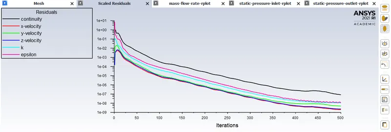
Residuals:
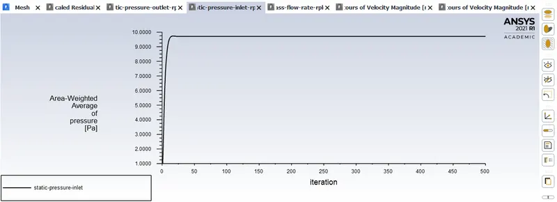
Plots:
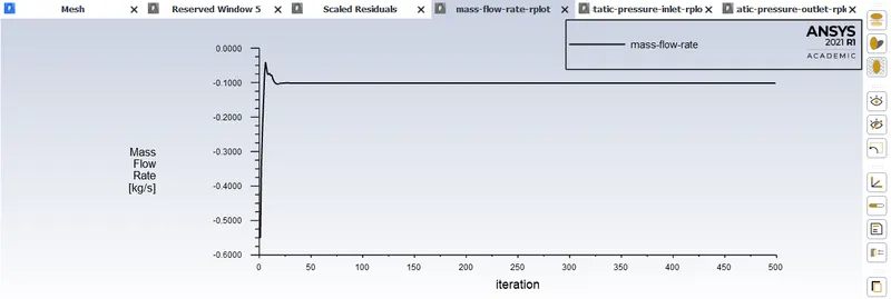
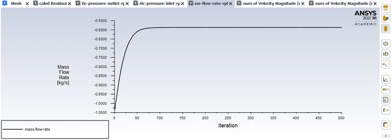
Mass flow rate
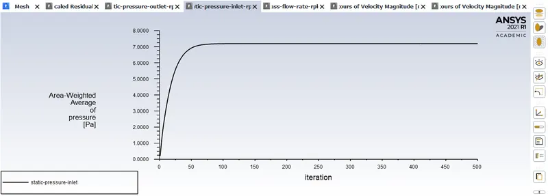
Static pressures:
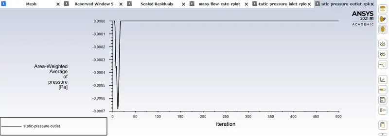
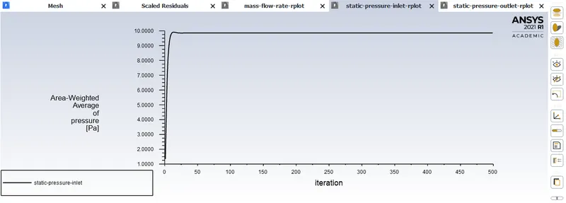
The Outlet static pressure is considered to be guage pressure and hence returns zero value.
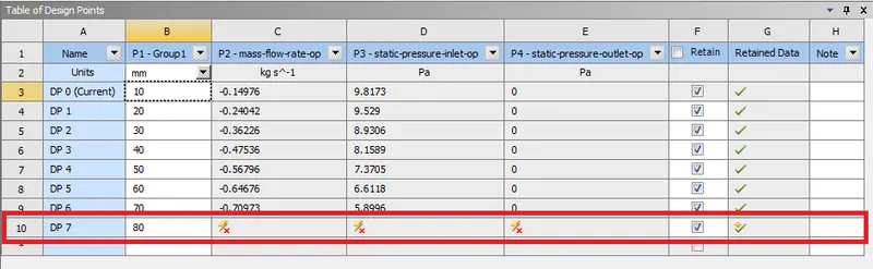
ERROR:
Wrong entry of lift value:
10% lift:
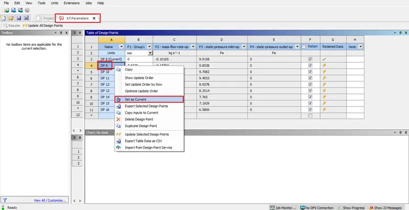
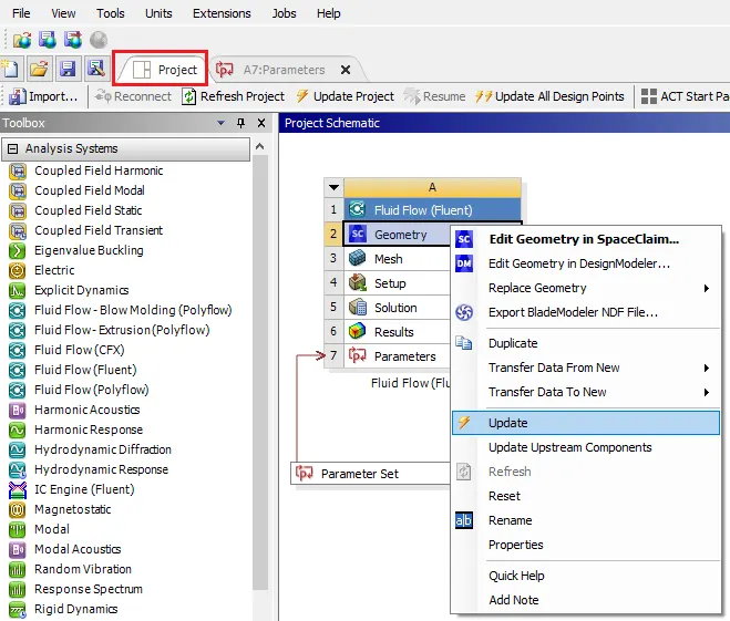
Update the other components in the case setup.
Setup:
Initialise the solution and run the calculation for 500 iterations.
Animation:
Residuals:
Plots:
CFD Post:
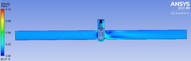
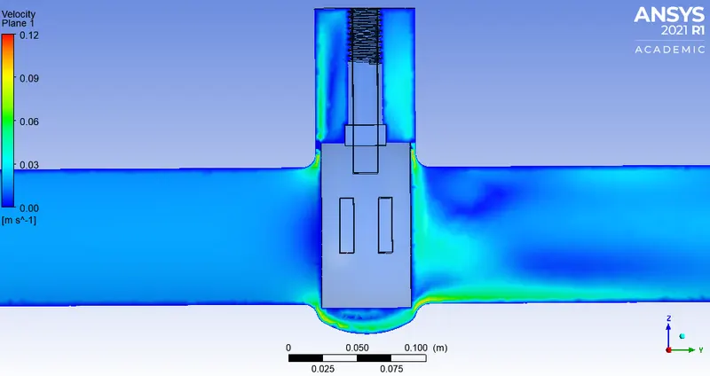
Velocity plot on plane:
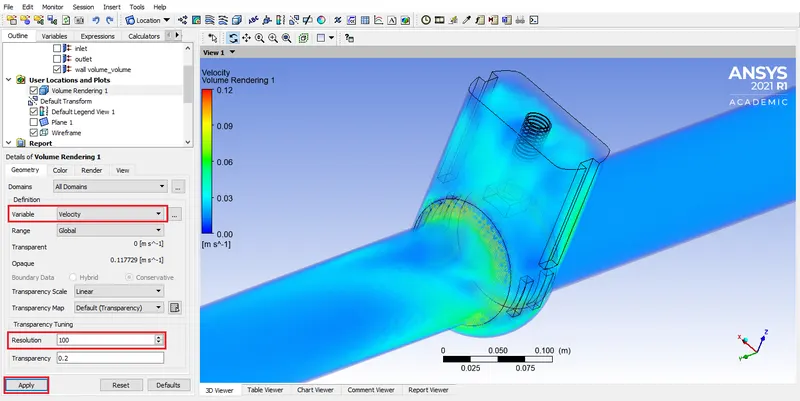
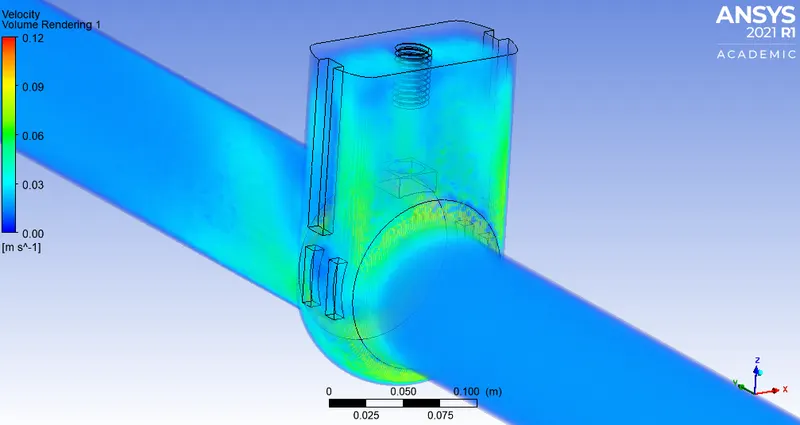
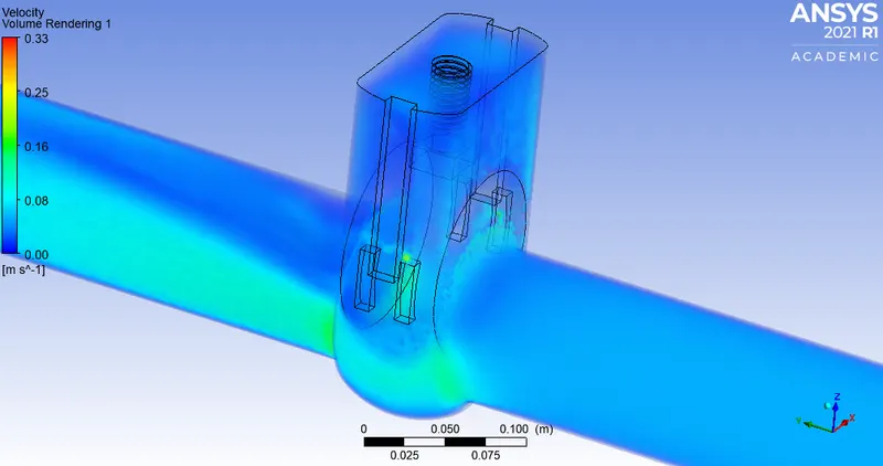
Volume Rendering:
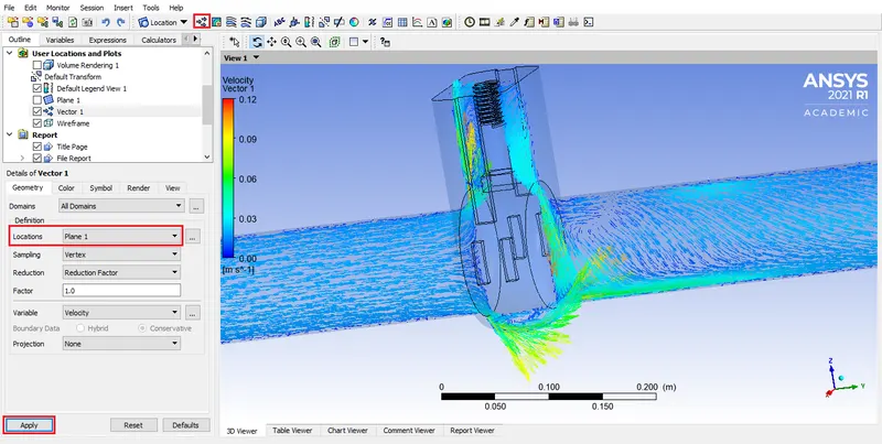
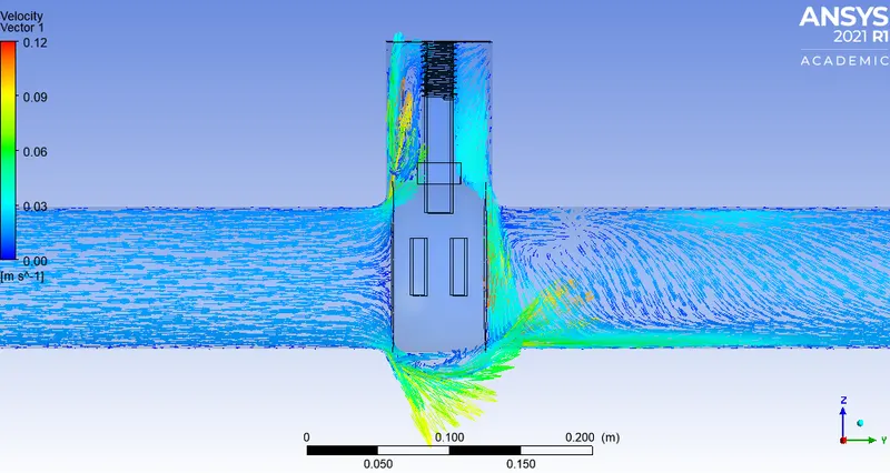
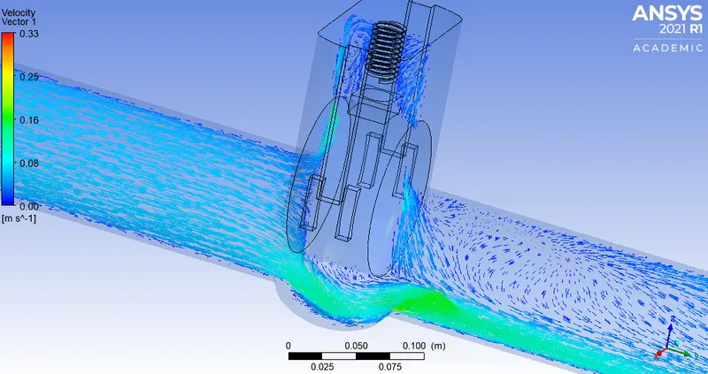
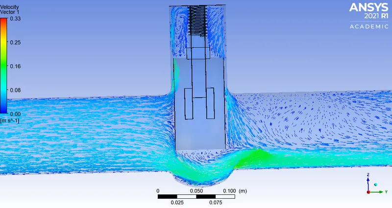
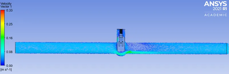
Vector plot:
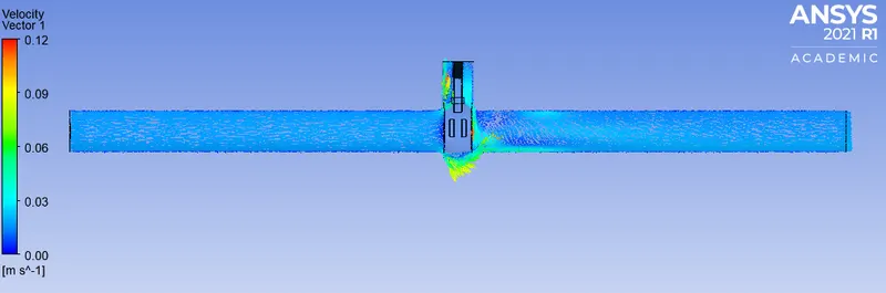
20% lift:
Animation:
Residuals:
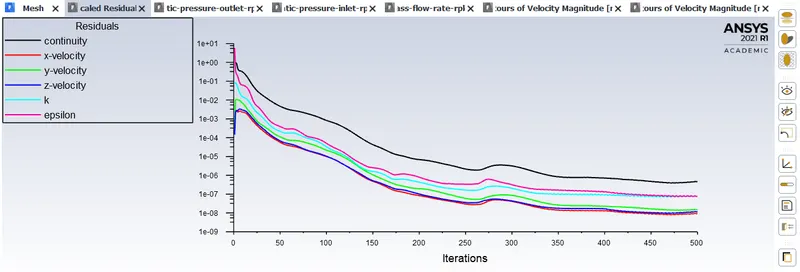
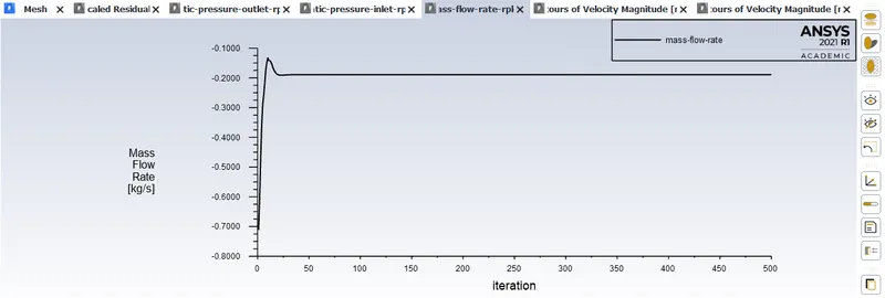
Plots:
CFD Post:
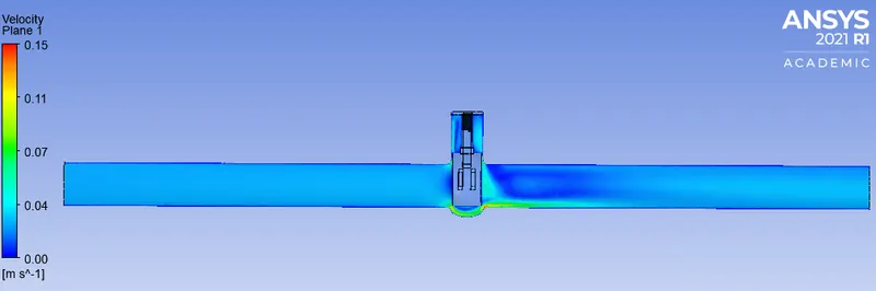
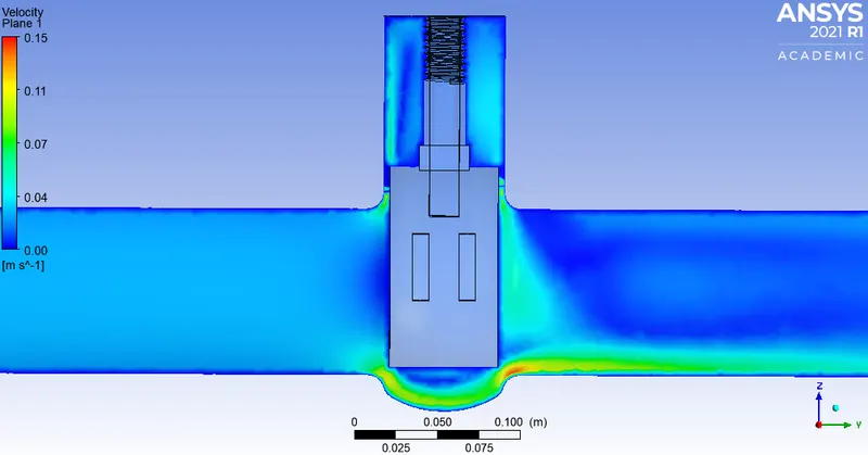
Velocity plot on plane:
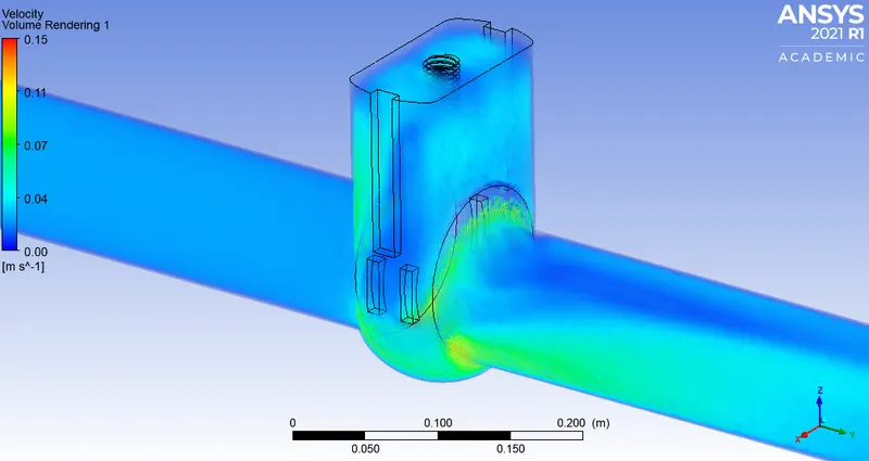
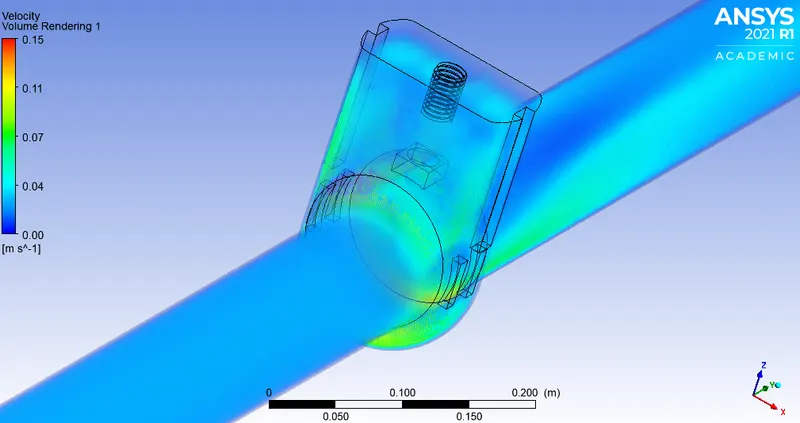
Volume Rendering:
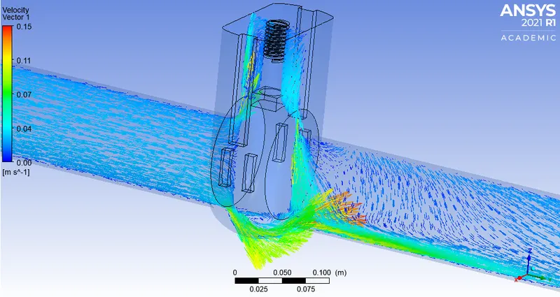
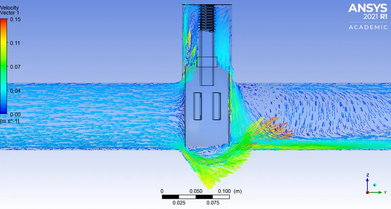
Vector plot:
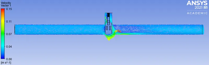
30% lift:
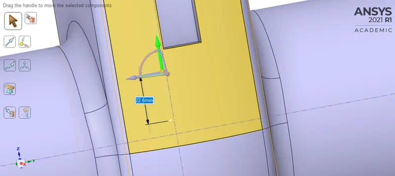
Animation:
Residuals:
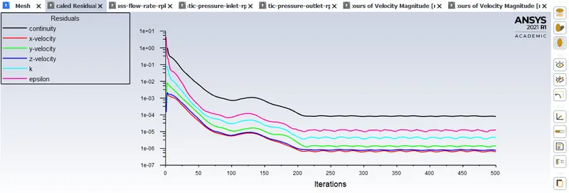
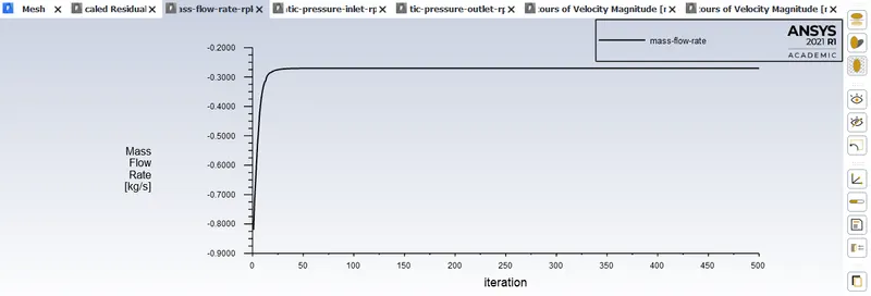
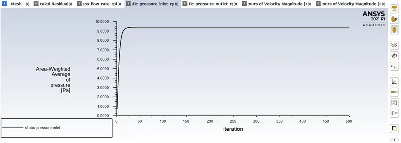
Plots:
CFD Post:
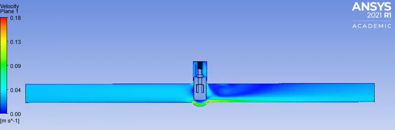
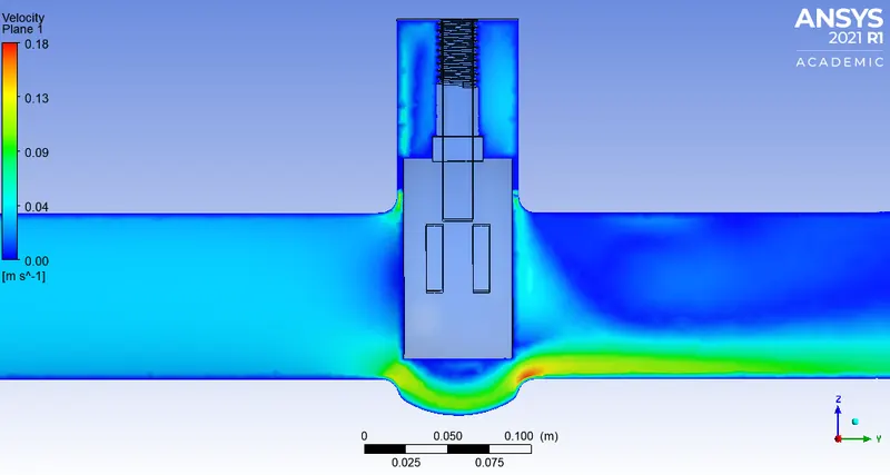
Velocity plot on plane:
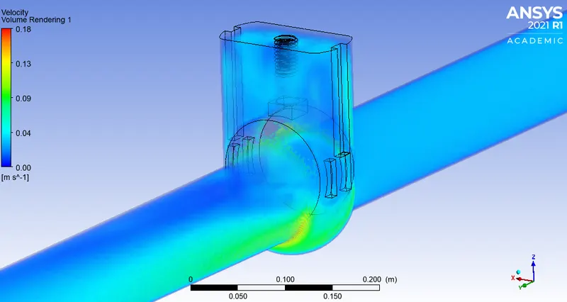
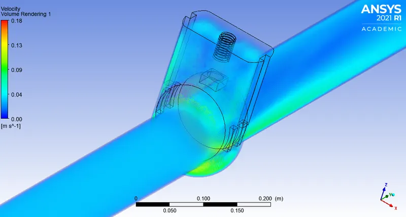
Volume Rendering:
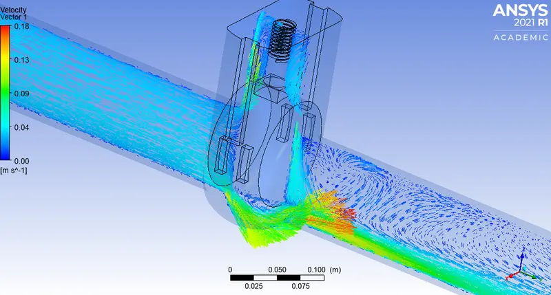
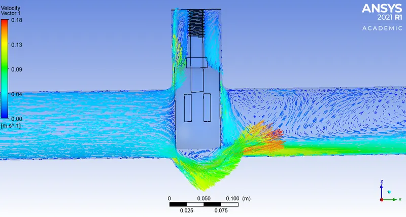
Vector plot:
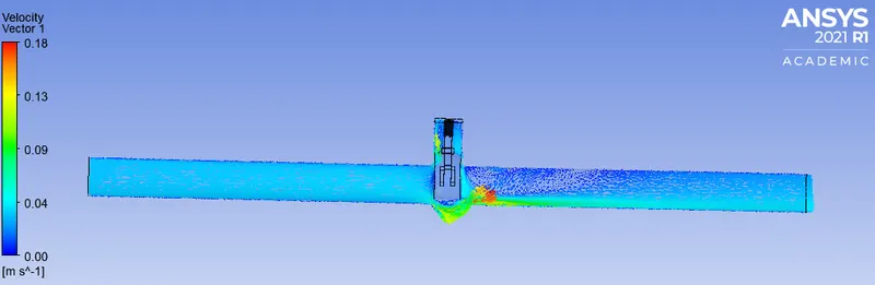
40% lift:
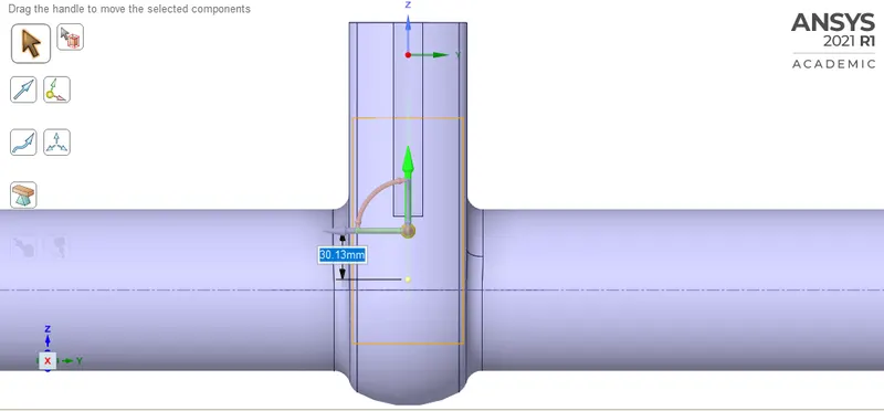
Animation:
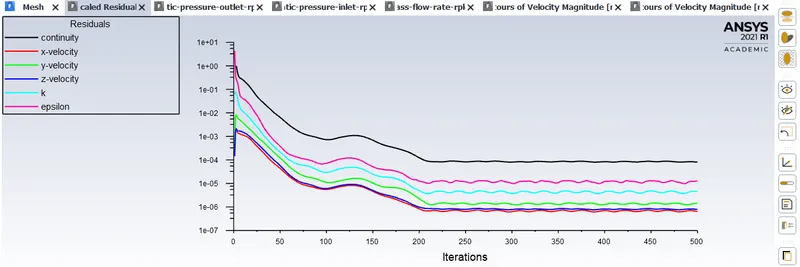
Residuals:
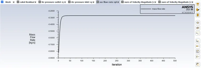
Plots: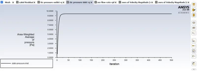
CFD Post:
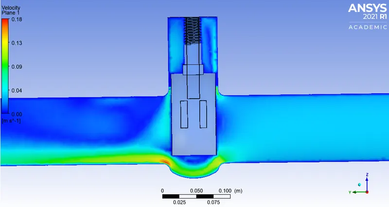
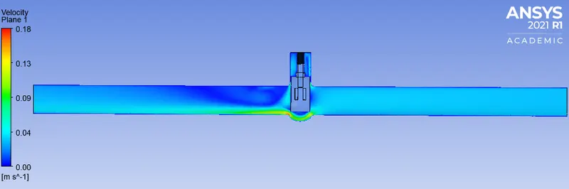
Velocity plot on plane:
Volume Rendering:
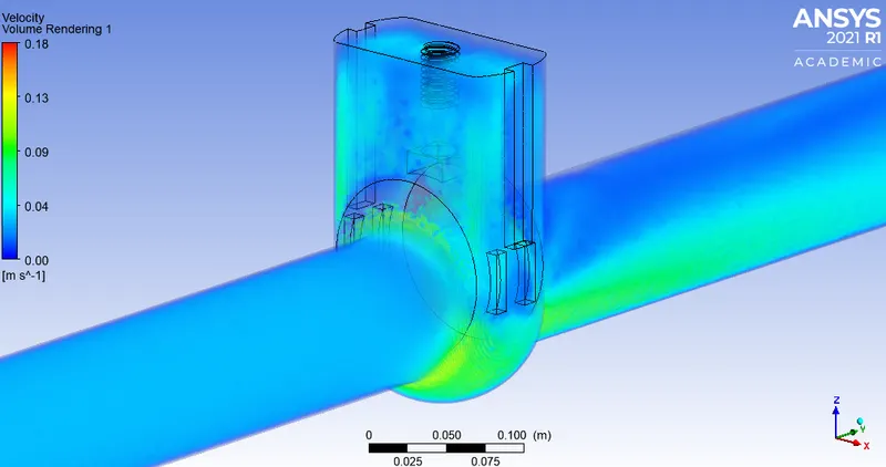

Vector plot:
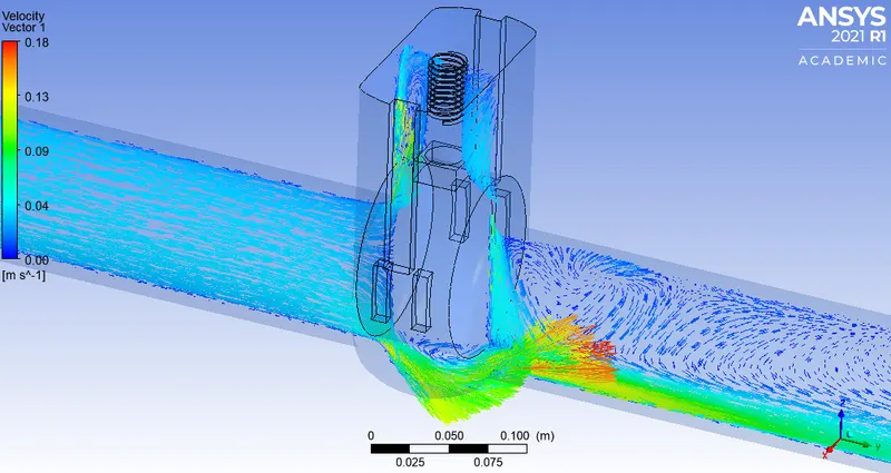
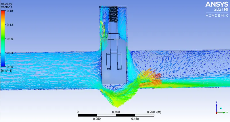
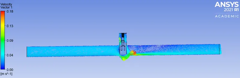
50% lift:
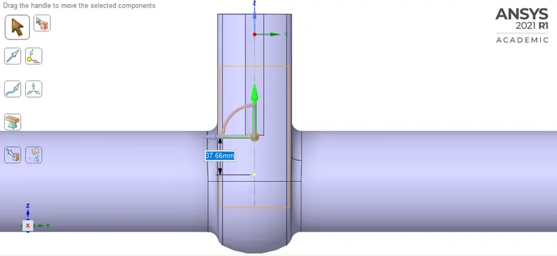
Animation:
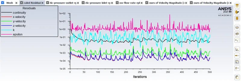
Residuals:
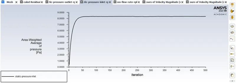
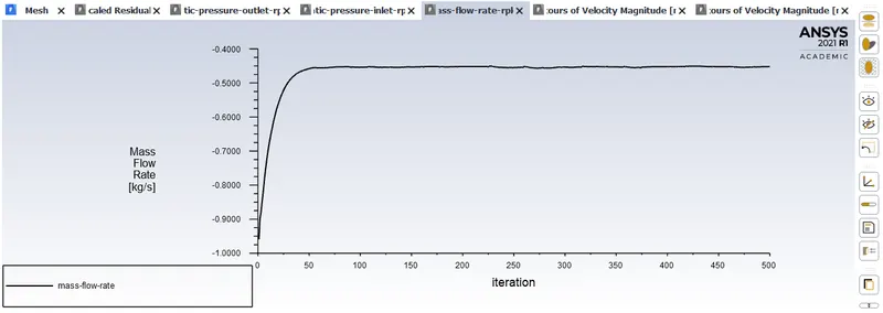
Plots:
CFD Post:
Velocity plot on plane:
Volume Rendering:
Vector plot:
60% lift:
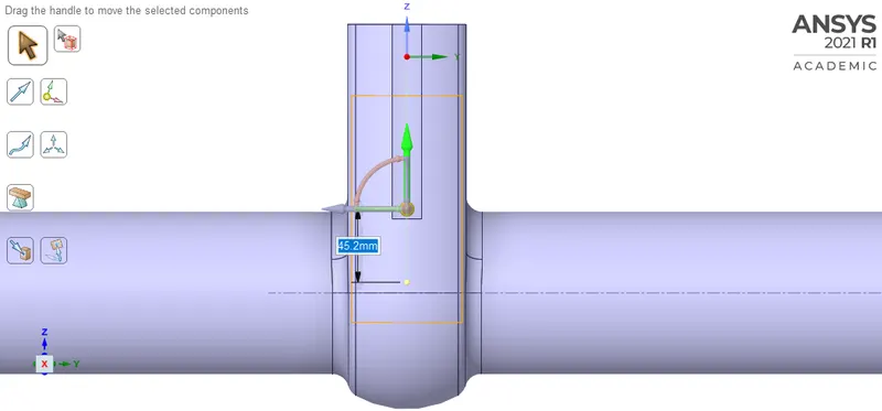
Animation:
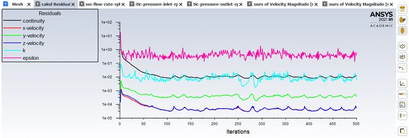
Residuals:
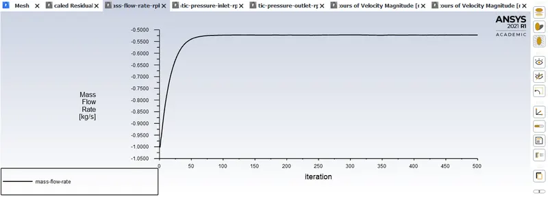
Plot:
CFD Post:
Velocity plot on plane:
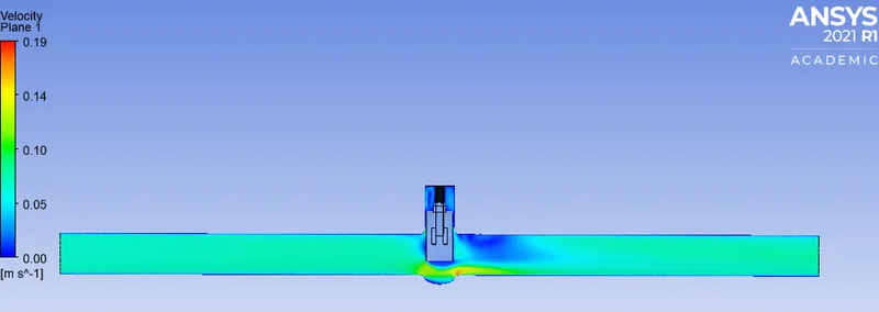
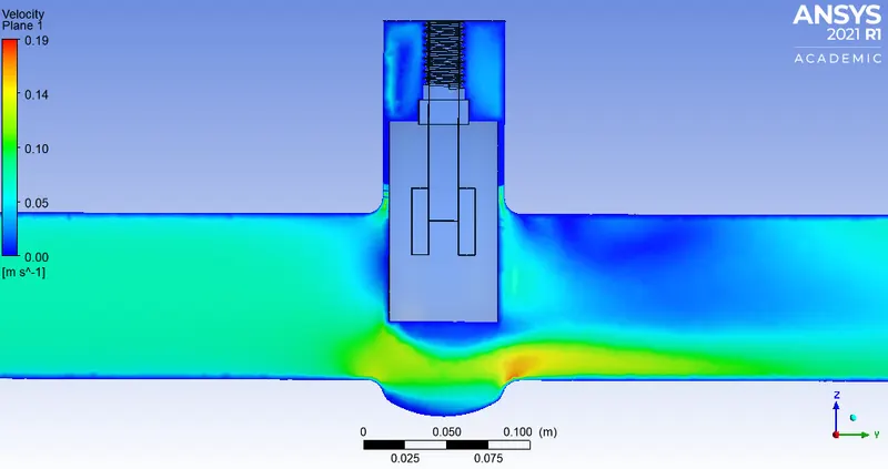
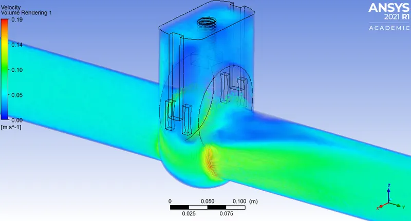
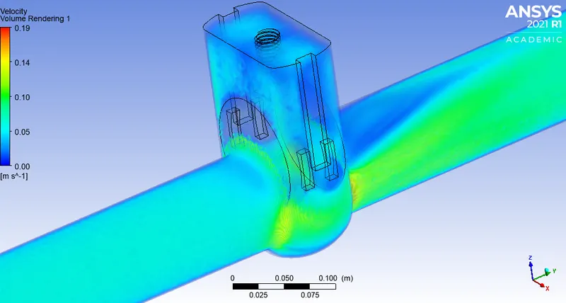
Volume Rendering:
Vector plot:
70% lift:
Animation:
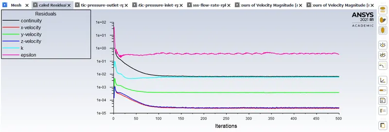
Residual:
Plots:
CFD Post:
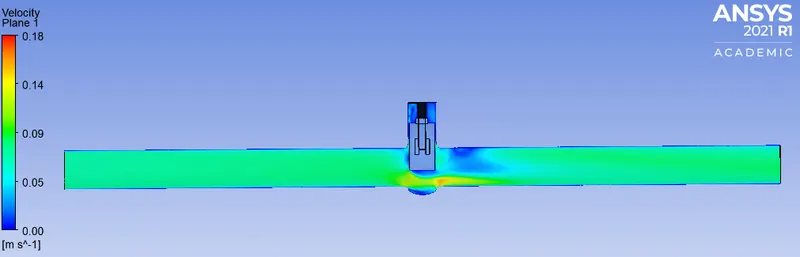
Velocity plot on plane:
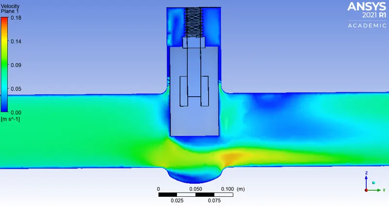
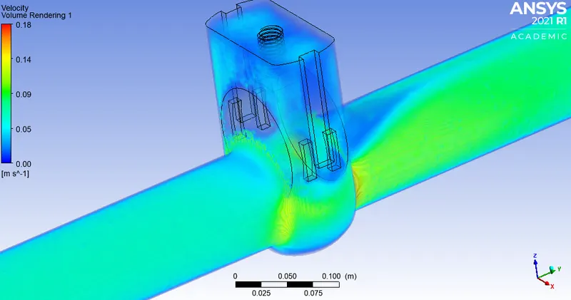
Volume Rendering:
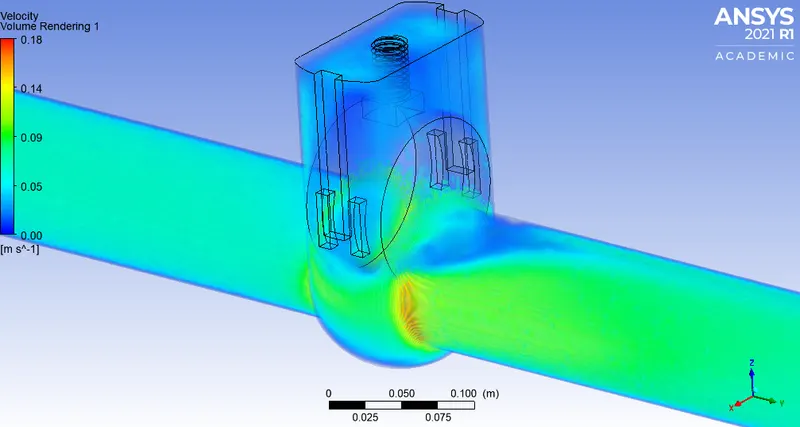
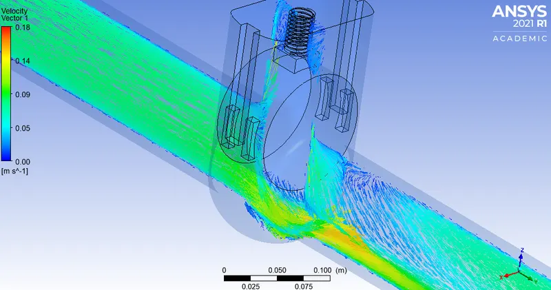
Vector plot:
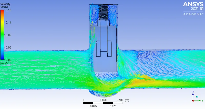
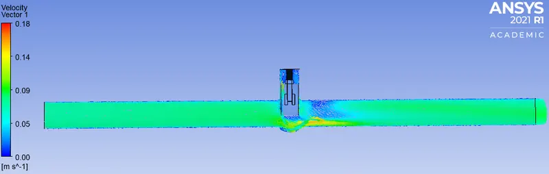
80% lift:
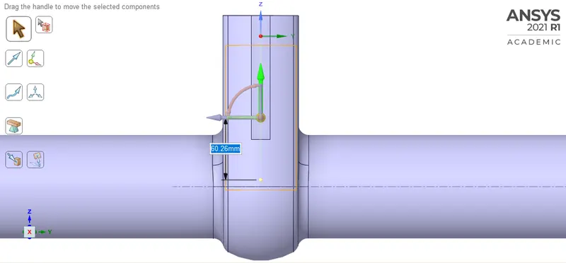
Animation:
Residuals:
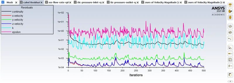
Plots:
CFD Post:
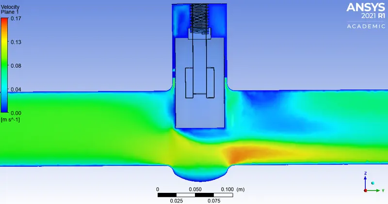
Velocity plot on plane:
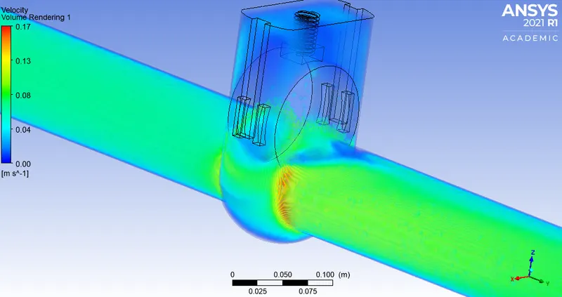
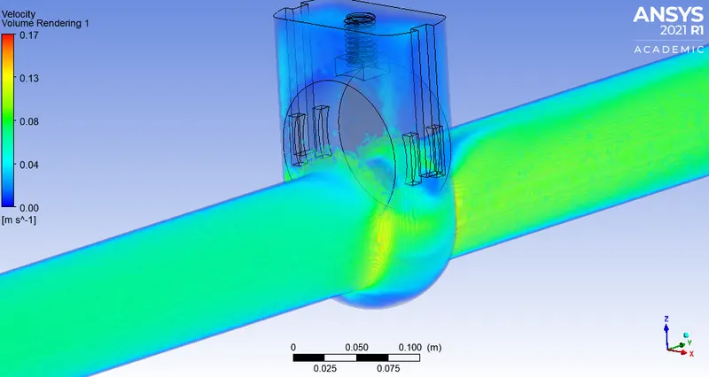
Volume Rendering:
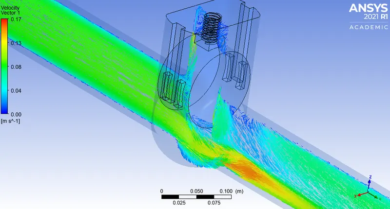
Vector plot:
RESULTS & CONCLUSION:
Flow coefficient:
`C_v=Q[sqrt((SW)/(DeltaP))]`
where,
Q is the rate of flow (expressed in US gallons per minute),
SG is the specific gravity of the fluid (for water = 1),
`DeltaP` is the pressure drop across the valve (expressed in psi).
Flow factor:
`K_v=Q[sqrt((SW)/(DeltaP))]`
where,
Kv is the flow factor (expressed in `(m^{3}/h)`
Q is the flowrate (expressed in cubic metres per hour `({m^{3}/h})`
SG is the specific gravity of the fluid (for water = 1),
`Delta P` is the differential pressure across the device (expressed in [bar]).
OR
`K_v` can be calculated from `C_v` using the equation:
`K_{v}=0.865*C_{v}`
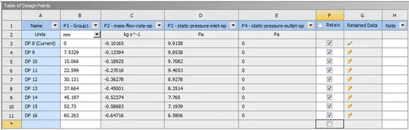
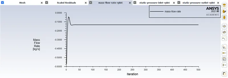
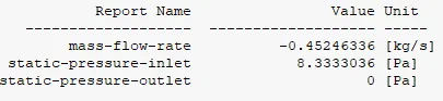
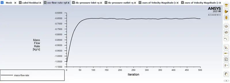
The negative mass flow rate indicates the quantity of fluid which exits from the outlet.
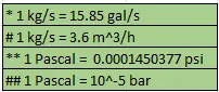
Tabulated results:

Plots:
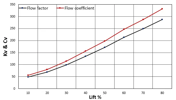
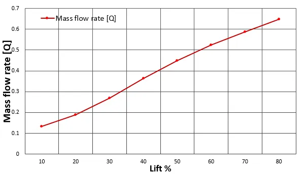
From the above graphs we can clearly see the effect of lift (gate disk) on Mass flow rate, Flow factor & Flow coeffecient.
- Lifting of gate disk will result in an increase in mass flow rate.
- As a result of increase in lift of gate disk values of flow factor increases.
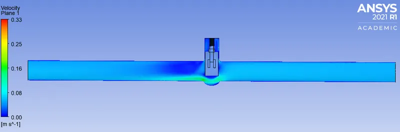
- Higher lift values allows easier motion of fluid from one the side of inlet to outlet.
Referances:
Reynold's number for flow through pipe:
https://www.cfd-online.com/Forums/fluent/150298-cant-delete-output-parameter.html
https://en.wikipedia.org/wiki/Flow_coefficient
kg/s to gallons per minute:
Pascals to psi:
https://www.unitconverters.net/pressure/pascal-to-psi.html
kg/s to m^3/h: