Week 9 - Parametric study on Gate valve.
PARAMETRIC STUDY ON GATE VALVE
AIM :-
To perform a parametric study on the gate valve simulation by setting the opening from 10 % to 80%.
OBJECTIVE :-
- To obtain the mass flow rates at the outlet for each design point.
- To calculate the flow coefficient and flow factor for each opening and plot the graph.
- To discuss the results of the mass flow rate and flow coefficient.
INTRODUCTION :-
Gate valve :-
Gate valves are used to shut off the flow of fluid by inserting a rectangular gate or wedge into the path of a flowing fluid. Gate valves require very little space along the pipe axis and hardly restrict the flow of fluid when the gate is fully opened enabling gate valves to offer straightway flow with very little pressure drop. Gate valves are mostly used with larger pipe diameters (from 2″ to the largest pipelines) since they are less complex to construct than other types of valves in large sizes.
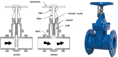
The gate valve, as illustrated below, generally consists of a gate-like disc, actuated by a screwed stem and hand-wheel which moves up and down at right angles to the flow. In the closed position, the disc seats against two faces to shut off flow. To retain the fluid in the pipeline, a gland is provided which is supplied with some type of packing to resist leakage.
 |
Working :-
Gate valves consist of three major components: body, bonnet, and trim. The body is generally connected to the piping by means of flanged, screwed, or welded connections. The bonnet, containing the moving parts, is joined to the body, generally with bolts, to permit cleaning and maintenance. The valve trim consists of the stem, the gate, the wedge, or disc, and the seat rings. The main operation mechanism is very simple. When the hand-wheel is turned, it rotates the stem, which is translated into the vertical movement of a gate via threads. They are considered multi-turn valves as it takes more than one 360° turn to fully open/close the valve. When the gate is lifted from the path of the flow, the valve opens and when it returns to its closed position, it seals the bore resulting in a full closure of the valve.
Body :- The body of a gate valve holds all of the operational parts of the valve. It is connected to the system with one of the mounting options below. The mounting option should be selected based on the current system mounting features and the type and size of the media.
Bonnet :- The bonnet of a gate valve contains the moving parts and is attached to the valve body. The bonnet can be removed from the body in order to allow for maintenance and replacing parts.
Trim :- The trim of a gate valve contains the functioning pieces of the valve: the stem, the gate, the disc or wedge, and the seat rings.
Advantages :-
- They have good shutoff characteristics.
- They are bidirectional.
- The pressure loss through the valve is minimal.
Disdvantages :-
- Gate valves are not quick opening or closing valves. Full-stem travel to open or close a gate valve requires many turns of its hand wheel or an actuator.
- Gate valves require large space envelope for installation, operation, and mainte- nance.
- The slow movement of the disc near the full-closed position results in high-fluid velocities, causing scoring of seating surfaces, referred to as wire drawing. It also causes galling of sliding parts.
- Some designs of gate valves are susceptible to thermal or pressure binding, depending upon the application.
- In systems experiencing high-temperature fluctuations, wedge-gate valves may have excessive leakage past the seats due to changes in the angular relationship between the wedge and the valve seats caused by piping loads on the valve ends.
- Repair or machining of valve seats in place is difficult.
- Socket or butt-welding end-gate valves in air, fuel gas, feedwater, steam, lube oil, and other systems are typical applications.
- Threaded-end gate valves may be used in air, gaseous, or liquid systems.Concern for leakage from threaded connection can be addressed by seal welding the threaded connection or by using thread sealants, as appropriate.
- In low-pressure and low-temperature systems such as fire protection systems’ water piping or water distribution pipelines, flanged gate valves are commonly used.
Geometry:-
- The below figure.1 is the geometry of a gate valve.
- Then we need to move the gate disc using move option towards the top of spindle as shown in figure.2.
- For different cases we need to give different lift for the gate disc from 10% to 80%.
- Then we need to parametrized the gate disc lift where we can edit the lift.
|
Figure.1 |
Figure.2 |
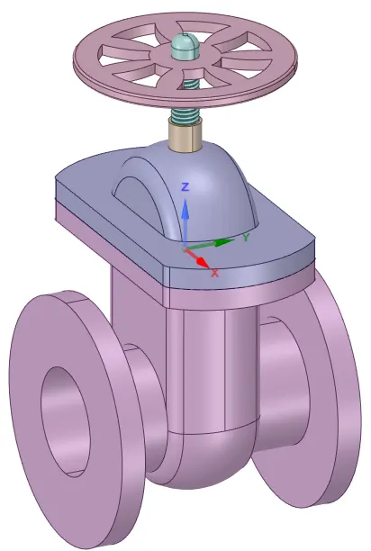
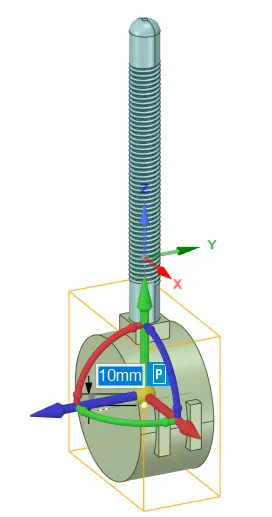
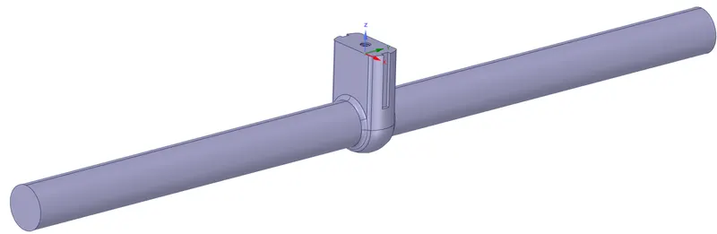
- Then we need to extract fluid volume from the original geometry as shown in below figure.
- Then we need to increase the fluid volume by pulling the pipe from both sides.
 |
Meshing:-
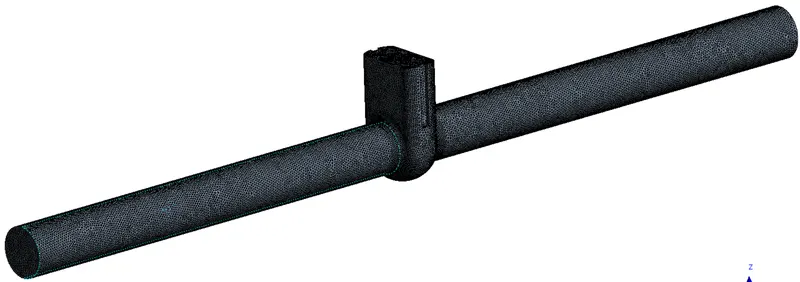
- Here we need to name the boundaries using named selection option as inlet and outlet. Then we need to generate mesh as shown in below figure.
- Element size --> 5 mm
- Mesh method --> All triangle method
- Number of Nodes --> 118694
- Number of Elements --> 595863
|
|
Setup:-
--> Models:-
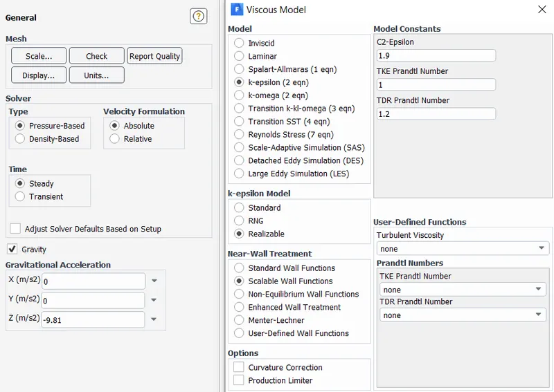
- Here we need to setup a solver. The solver type is pressure based, steady state and absolute velocity formation as shown in below figure and gravity in Z-direction.
- After the solver setup we need to select K-epsilon Realizable model, then we need to select Scalable wall functions as shown in below figure.
 |
--> Materials and Boundary conditions :-
| Materials | Density (Kg/m^3) | Viscosity (Kg/ms) |
| Water | 998.2 | 0.001003 |
| Zone | Boundary condition |
| Inlet | Pressure inlet = 10 pascal |
| Outlet | Guage pressure= 0 pascal |
--> Solution initializtion:-
- After creating boundary conditions we need to initialize the solution using Standard initialization and computing from Inlet.
RESULTS :-
Calculation of flow coefficient and flow factor :-
Flow coefficient :- The flow coefficient of a device is a relative measure of its efficiency at allowing fluid flow. It describes the relationship between the pressure drop across an orifice valve or other assembly and the corresponding flow rate.
`Cv= Q sqrt ((SG) / (Delta P)`
where,
- Q is the rate of flow (expressed in US gallons per minute),
- SG is the specific gravity of the fluid (for water = 1),
- ΔP is the pressure drop across the valve (expressed in psi).
Flow factor :- The metric equivalent flow factor (Kv; commonly used everywhere else in the world with the exception of the United States) is calculated using metric units :
`Kv =Q sqrt ((SG) / (Delta P)`
`Kv = 0.865 * Cv`
where,
- Kv is the flow factor (expressed in {\displaystyle [m^{3}.h^{-1}]}
 ).
- Q is the flowrate (expressed in cubic metres per hour [{\displaystyle m^{3}/h}
 ]),
- SG is the specific gravity of the fluid (for water = 1),
- ∆P is the differential pressure across the device (expressed in [bar]).
Case 1:- 10mm lift
|
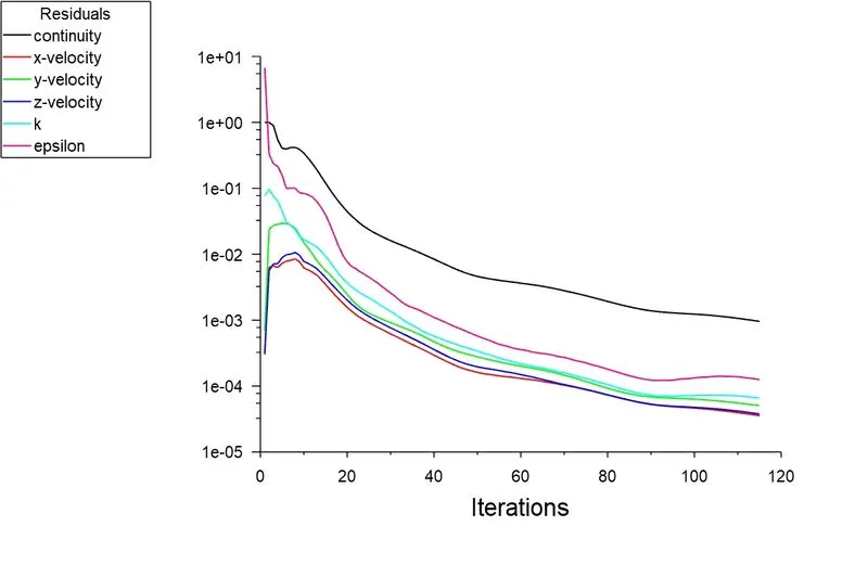
Residuals plot
|
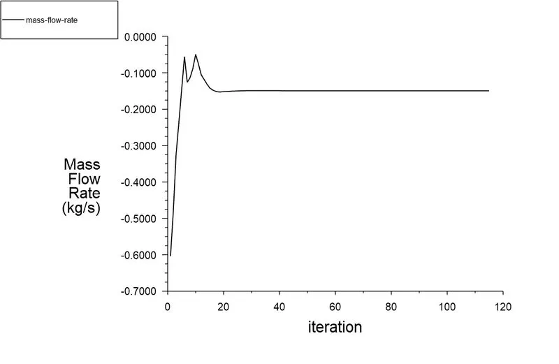
Mass flow rate plot :- -0.1493 Kg s^-1
|
|
Velocity contour plot
|
Mass flow rate = `0.1493 (Kg)/s`
Flow rate Q = `3.6 * 0.1493 = 0.5374 (m^3)/h`
Specific gravity SG = 1
Inlet pressure = 10pa
Outlet pressure = 0.1529pa
Pressure difference ∆P = Inlet pressure - Outlet pressure = 10 - 0.1529 = 9.8471pa =`9.8471e-05`bar
Flow factor `Kv =Q sqrt ((SG) / (Delta P)`
`Kv = 0.5374 sqrt(1/(9.8471e-05))`
`Kv = 54.155 (m^3)/h`
Flow coefficient `Cv = (Kv)/0.865`
`Cv = 54.155/0.865`
`Cv=62.6`
Case 2:- 20mm lift
|
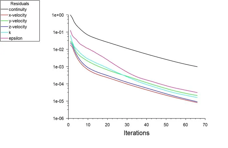
Residuals plot
|
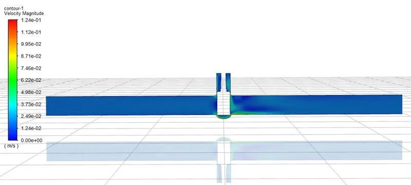
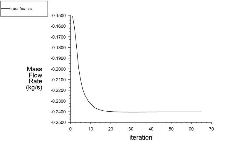
Mass flow rate plot :- -0.2402 Kg s^-1
|
|
Velocity contour plot
|
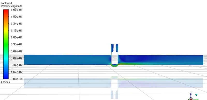
Mass flow rate = `0.2402 (Kg)/s`
Flow rate Q = `3.6 * 0.2402 = 0.86472 (m^3)/h`
Specific gravity SG = 1
Inlet pressure = 10pa
Outlet pressure = 0.5605pa
Pressure difference ∆P = Inlet pressure - Outlet pressure = 10 - 0.5605 = 9.4395pa =`9.4395e-05`bar
Flow factor `Kv =Q sqrt ((SG) / (Delta P)`
`Kv = 0.86472 sqrt(1/(9.4395e-05))`
`Kv = 89 (m^3)/h`
Flow coefficient `Cv = (Kv)/0.865`
`Cv = 89/0.865`
`Cv=102.89`
Case 3:- 30mm lift
|
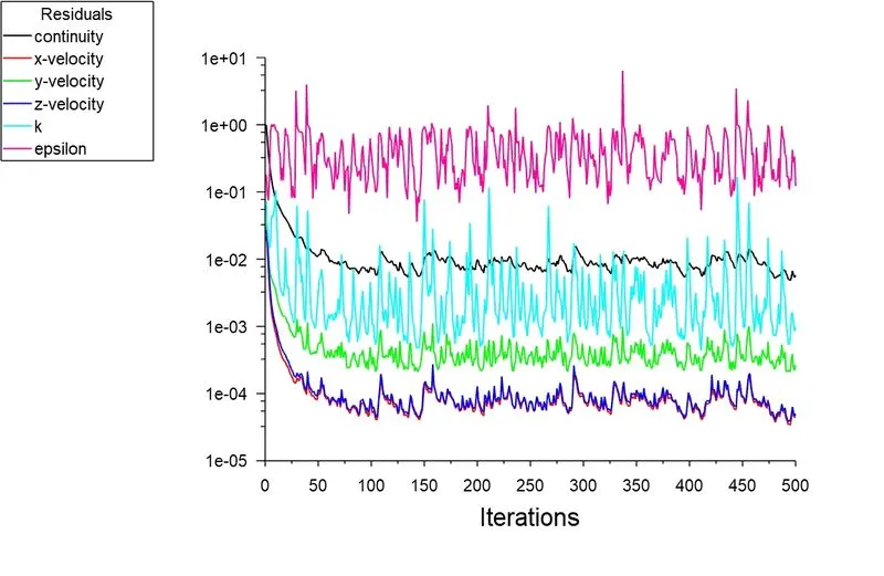
Residuals plot
|
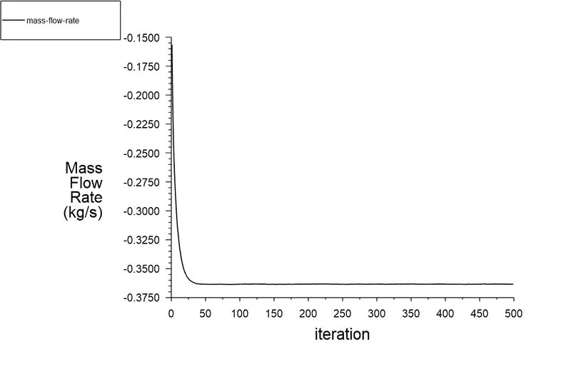
Mass flow rate plot :- -0.3634 Kg s^-1
|
|
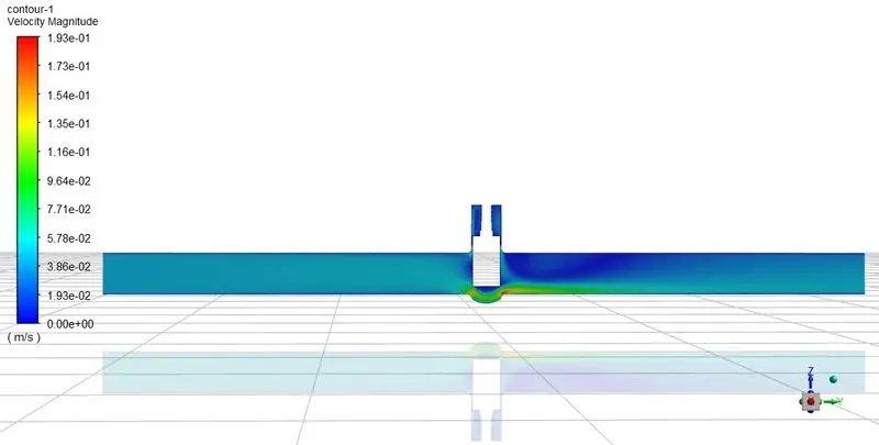
Velocity contour plot
|
Mass flow rate = `0.3634 (Kg)/s`
Flow rate Q = `3.6 * 0.3634 = 1.3082 (m^3)/h`
Specific gravity SG = 1
Inlet pressure = 10pa
Outlet pressure = 1.135pa
Pressure difference ∆P = Inlet pressure - Outlet pressure = 10 - 1.135 = 8.865pa =`8.865e-05`
Flow factor `Kv =Q sqrt ((SG) / (Delta P)`
`Kv = 1.3082 sqrt(1/(8.865e-05))`
`Kv = 138.94 (m^3)/h`
Flow coefficient `Cv = (Kv)/0.865`
`Cv = 138.94/0.865`
`Cv=160.62`
Case 4:- 40mm lift
|
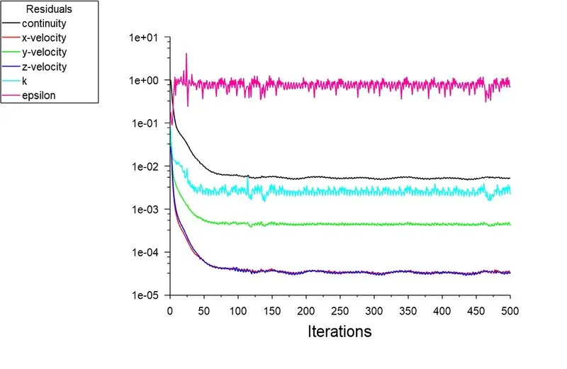
Residuals plot
|
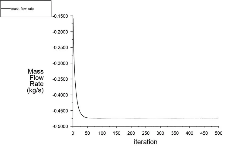
Mass flow rate plot :- -0.4736 Kg s^-1
|
|
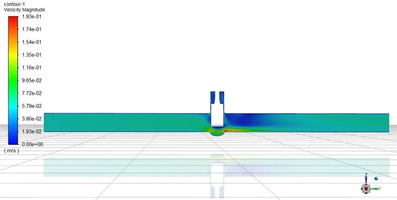
Velocity contour plot
|
Mass flow rate = `0.4736 (Kg)/s`
Flow rate Q = `3.6 * 0.4736 = 1.705 (m^3)/h`
Specific gravity SG = 1
Inlet pressure = 10pa
Outlet pressure = 1.924pa
Pressure difference ∆P = Inlet pressure - Outlet pressure = 10 - 1.924 = 8.0761pa =`8.076e-05`bar
Flow factor `Kv =Q sqrt ((SG) / (Delta P)`
`Kv = 1.705 sqrt(1/(8.076e-05))`
`Kv = 189.725 (m^3)/h`
Flow coefficient `Cv = (Kv)/0.865`
`Cv = 189.725/0.865`
`Cv=219.33`
Case 5:- 50mm lift
|
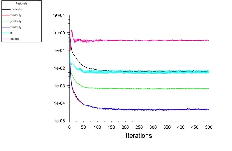
Residuals plot
|
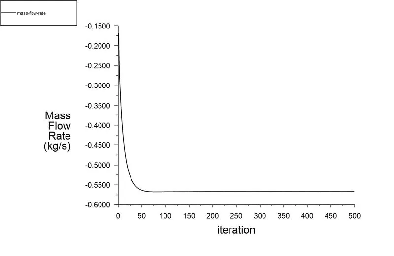
Mass flow rate plot :- -0.5667 Kg s^-1
|
|
Velocity contour plot
|
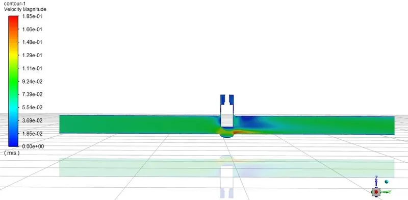
Mass flow rate = `0.5667 (Kg)/s`
Flow rate Q = `3.6 * 0.5667 = 2.04 (m^3)/h`
Specific gravity SG = 1
Inlet pressure = 10pa
Outlet pressure = 2.716pa
Pressure difference ∆P = Inlet pressure - Outlet pressure = 10 - 2.716 = 7.284pa =`7.284e-05`bar
Flow factor `Kv =Q sqrt ((SG) / (Delta P)`
`Kv = 2.04 sqrt(1/(7.284e-05))`
`Kv = 239.02 (m^3)/h`
Flow coefficient`Cv = (Kv)/0.865`
`Cv = 239.02/0.865`
`Cv=276.33`
Case 6:- 60mm lift
|
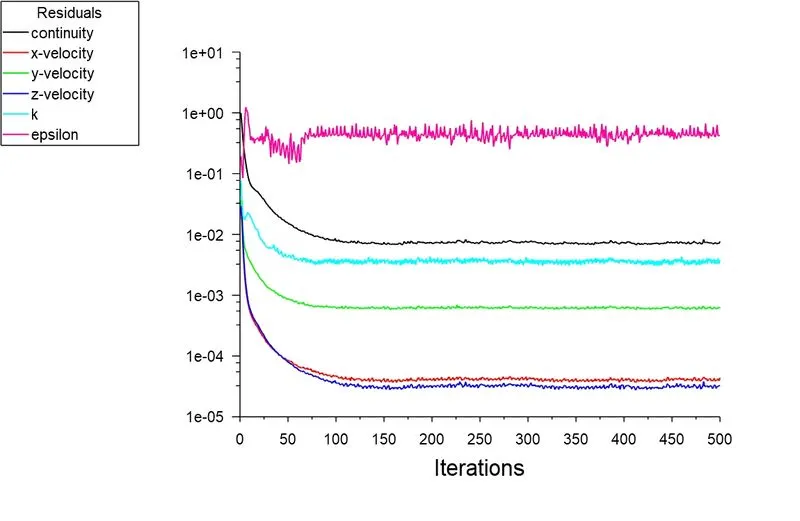
Residuals plot
|
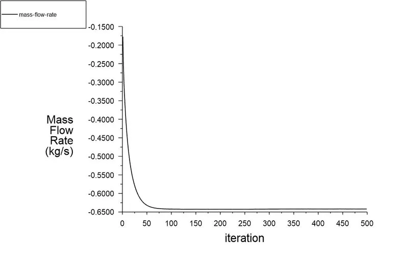
Mass flow rate plot :- -0.6418 Kg s^-1
|
|
Velocity contour plot
|
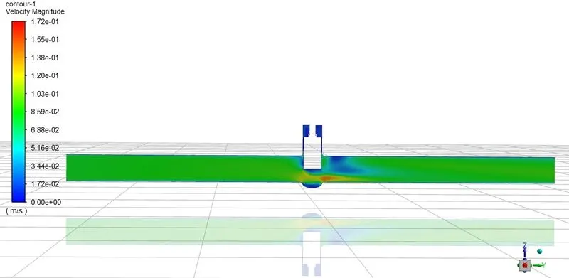
Mass flow rate = `0.6418 (Kg)/s`
Flow rate Q = `3.6 * 0.6418 = 2.3104 (m^3)/h`
Specific gravity SG = 1
Inlet pressure = 10pa
Outlet pressure = 3.684pa
Pressure difference ∆P = Inlet pressure - Outlet pressure = 10 - 3.684 = 6.316pa =`6.316e-05`bar
Flow factor `Kv =Q sqrt ((SG) / (Delta P)`
`Kv = 2.3104 sqrt(1/(6.316e-05))`
`Kv = 290.71 (m^3)/h`
Flow coefficient `Cv = (Kv)/0.865`
`Cv = 290.71/0.865`
`Cv=336.08`
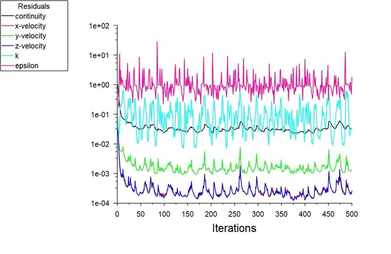
Case 7:- 70mm lift
|
Residuals plot
|
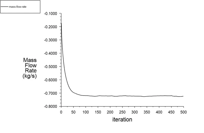
Mass flow rate plot :- -0.7232 Kg s^-1
|
|
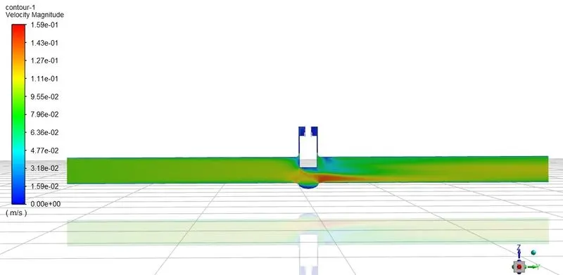
Velocity contour plot
|
Mass flow rate = `0.7232 (Kg)/s`
Flow rate Q = `3.6 * 0.7232 = 2.6035 (m^3)/h`
Specific gravity SG = 1
Inlet pressure = 10pa
Outlet pressure = 4.386pa
Pressure difference ∆P = Inlet pressure - Outlet pressure = 10 - 4.386 = 5.614pa =`5.614e-05`bar
Flow factor `Kv =Q sqrt ((SG) / (Delta P)`
`Kv = 2.6035 sqrt(1/(5.614e-05))`
`Kv = 347.47 (m^3)/h`
Flow coefficient `Cv = (Kv)/0.865`
`Cv = 347.47/0.865`
`Cv=401.7`
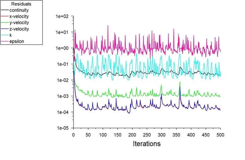
Case 8:- 80mm lift
|
Residuals plot
|
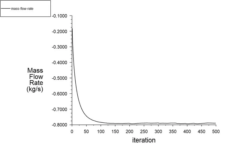
Mass flow rate plot :- -0.7895 Kg s^-1
|
|
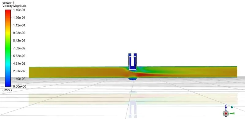
Velocity contour plot
|
Mass flow rate = `0.7895 (Kg)/s`
Flow rate Q = `3.6 * 0.7895 = 2.8422 (m^3)/h`
Specific gravity SG = 1
Inlet pressure = 10pa
Outlet pressure = 5.677pa
Pressure difference ∆P = Inlet pressure - Outlet pressure = 10 - 5.677 = 4.323pa =`4.323e-05`bar
Flow factor `Kv =Q sqrt ((SG) / (Delta P)`
`Kv = 2.8422 sqrt(1/(4.323e-05))`
`Kv = 432.27 (m^3)/h`
Flow coefficient `Cv = (Kv)/0.865`
`Cv = 432.27/0.865`
`Cv=499.74`
| Lift of gate disc (mm) |
Inlet Pressure (pa) |
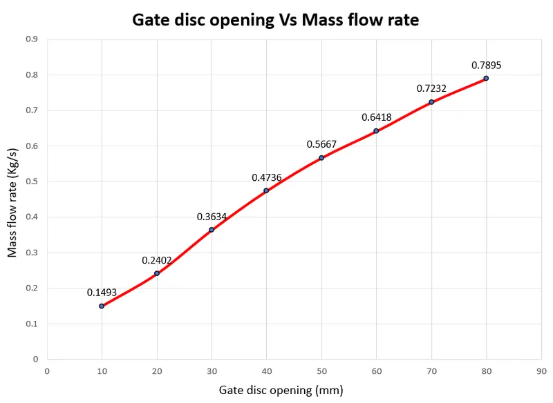
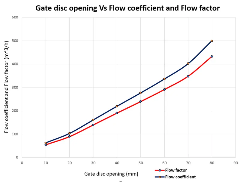
Outlet Pressure (pa) | Pressure difference (pa) | Mass flow rate (Kg/s) | Flow factor (Kv) (`m^3/h`) | Flow coefficient (Cv) |
| 10 | 10 | 0.153 | 9.8471 | 0.1493 | 54.155 | 62.6 |
| 20 | 10 | 0.560 | 9.439 | 0.2402 | 89 | 102.89 |
| 30 | 10 | 1.135 | 8.865 | 0.3634 | 138.94 | 160.62 |
| 40 | 10 | 1.924 | 8.076 | 0.4736 | 189.725 | 219.33 |
| 50 | 10 | 2.716 | 7.284 | 0.5667 | 239.02 | 276.33 |
| 60 | 10 | 3.684 | 6.316 | 0.6418 | 290.71 | 336.08 |
| 70 | 10 | 4.386 | 5.614 | 0.7232 | 347.47 | 401.7 |
| 80 | 10 | 5.677 | 4.323 | 0.7895 | 432.27 | 499.74 |
 |
 |
CONCLUSION :-
- From the above results and contour plots we can clearly see that as the lift of gate disc increases,the velocity of the flow also increases. We can observe it in a velocity contour plot in starting cases the velocity is low and as the lift of disc increases velocity increases.
- From above results it is observed that pressure of flow on the inlet side is high and as the flow passes through the opening, pressure decreases.
- From which we can say that lower the lift of the disc higher is the pressure drop and lower flow rate through the valve.
- From the above table we can clearly see that as the lift of the disc increases the mass flow rate increases.
- As the mass flow rate increase flow factor, flow coefficient also increases.