Week 9 - Parametric study on Gate valve.
Flow coefficient and flow factor:
en.wikipedia.org/wiki/Flow_coefficient
For a device, flow coefficient is a measure of its efficiency at which it allows flow through it. It describes the relationship between pressure drop across an orifice valve or other assembly and the corresponding fllow rate.
Flow coefficient Cv (or flow-capacity rating of valve) can be written as :

- here,
- Q = Rate of flow (in US gallons per minute),
- SG = Specific gravity of the fluid (for water = 1),
- ΔP = Pressure drop across the valve ( psi).
The flow coefficient Cv is called as the volume (in US gallons) of water at 60 °F that will flow per minute through a valve with a pressure drop of 1 psi across the valve.
Flow coefficient is a parameter used for comparing valve capacities and sizing valves for different applications.
Flow factor:
The metric equivalent flow factor (Kv; used everywhere else in the world with the except United States) is calculated using metric units :

here
- Kv = Flow factor
- Q = Flowrate (cubic metres per hour)
- SG = Specific gravity of the fluid (for water = 1),
- ∆P = Differential pressure across the device [bar].
Kv can be calculated from Cv using the equation:

Wall functions come into play a vital role when using turbulence modeling. The flow is always laminar near the wall, hence turbulence modeling will not be valid in this laminar regime. That is the main reason to use wall functions in turbulent modeling to capture the inner laminar field variables in the flow.
Standard wall functions
These have been most widely used in industrial flows. They are provided as a default option in ANSYS FLUENT.
The standard wall functions works reasonably well for a wide range of wall-bounded flows. However, they become less reliable when the flow situations depart from the ideal conditions that are assumed in their derivation. Among others, the constant-shear and local equilibrium assumptions are the ones that most restrict the universality of the standard wall functions. Accordingly, when the near-wall flows are subjected to severe pressure gradients, and when the flows are in strong non-equilibrium, the quality of the predictions is likely to be compromised.
Scalable wall functions:
The purpose of scalable wall functions is to force the usage of the log law in conjunction with the standard wall functions approach.
Aim:
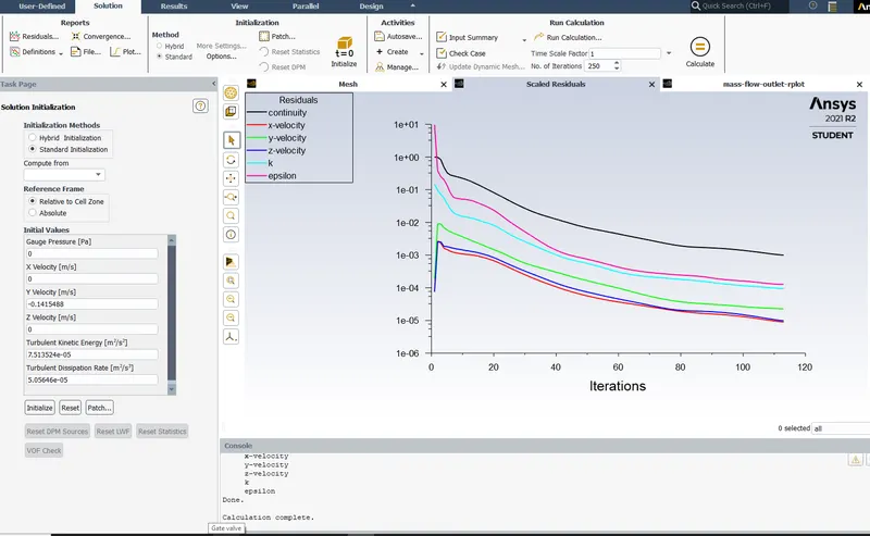
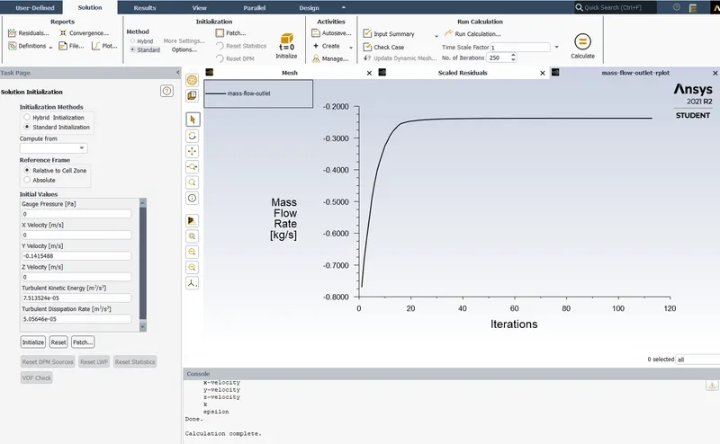
Obtain the mass flow rates at the outlet for each design point.
Solution procedure:
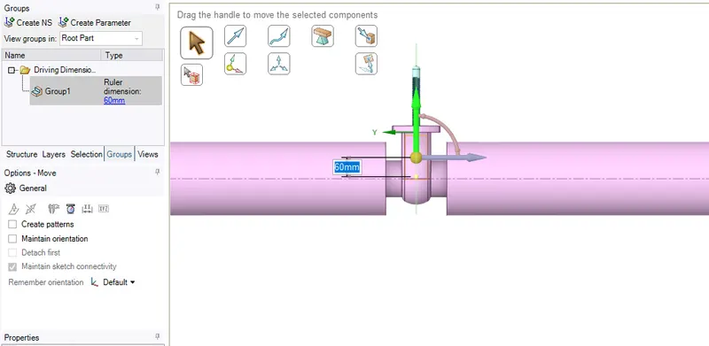
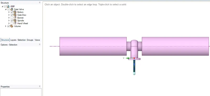
Project schematic:
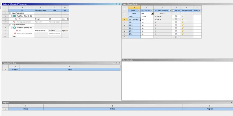
10mm
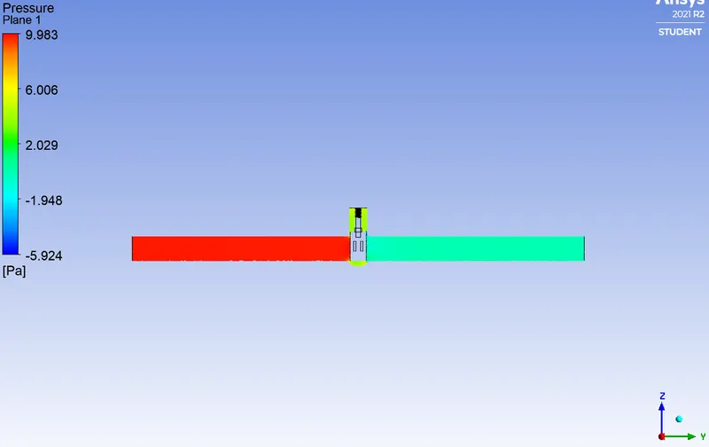
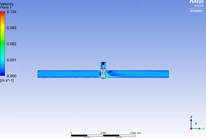
20mm
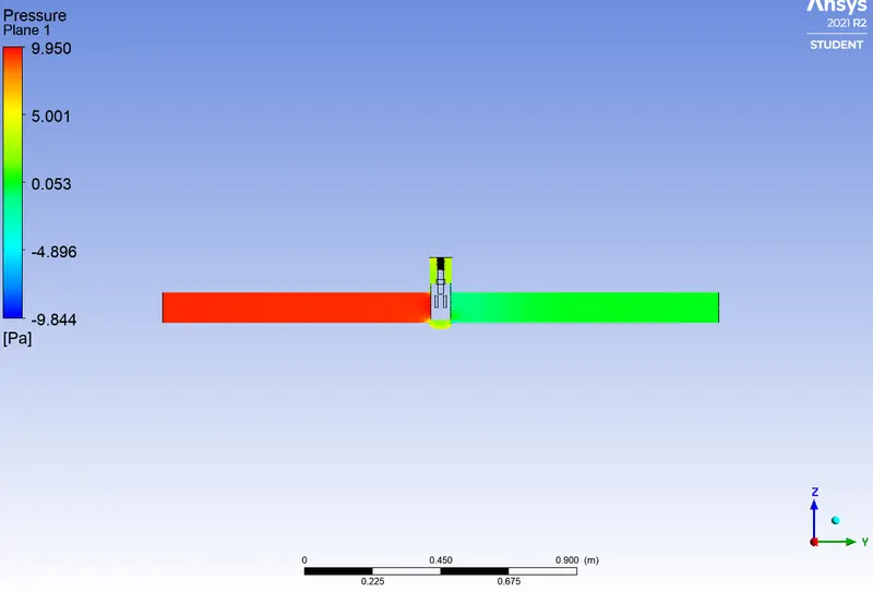
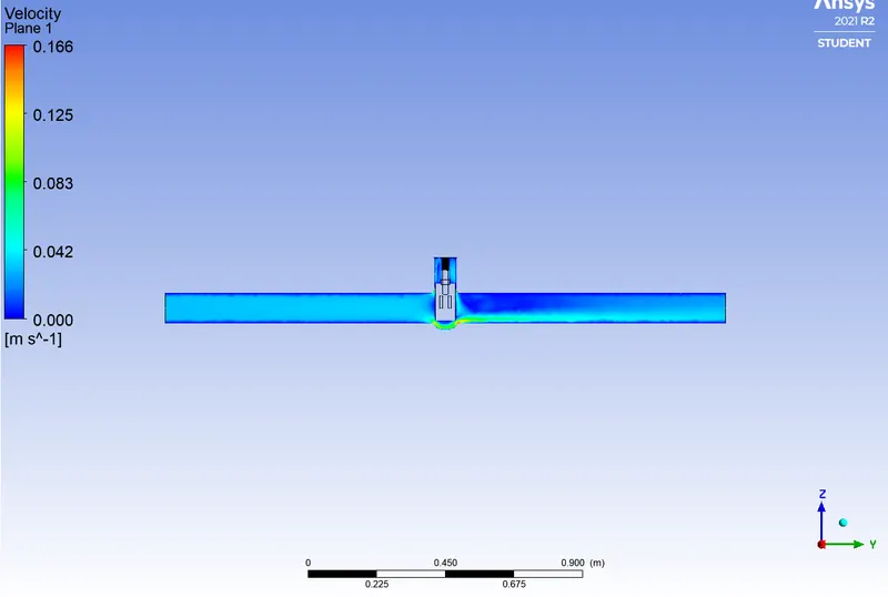
30mm lift of gate
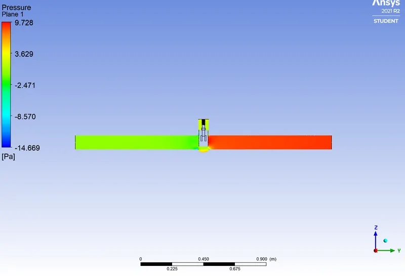
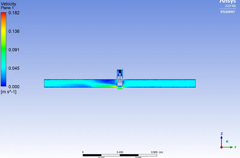
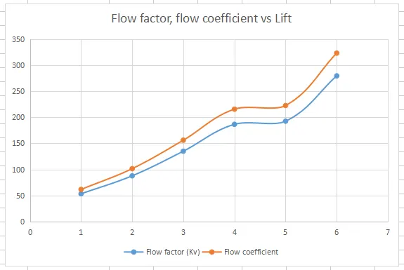
Values of Flow factor and flow coefficient
| Lift(mm) | Flow rate (kg/sec) | Discharge (m^3/hr) | dP (Pa) | dP (Bar) | Flow factor (Kv) | Flow coefficient |
| 10 | 0.14818 | 0.533448 | 10 | 0.0001 | 53.3448 | 61.67028902 |
| 20 | 0.238 | 0.8568 | 9.52 | 0.0000952 | 87.81343861 | 101.5184261 |
| 30 | 0.355 | 1.278 | 8.96 | 0.0000896 | 135.0133922 | 156.0848465 |
| 40 | 0.468 | 1.6848 | 8.16 | 0.0000816 | 186.5104949 | 215.6190692 |
| 50 | 0.484 | 1.7424 | 8.19 | 0.0000819 | 192.5333252 | 222.5818789 |
| 60 | 0.633 | 2.2788 | 6.652 | 0.00006652 | 279.4023731 | 323.0085238 |
Plot: