Week 9 - Mini project - Flow over an Airfoil
OBJECTIVE:
Simulate flow over a 4-digit airfoil, i.e. NACA 2412 Airfoil, and calculate the following parameters:
- Drag coefficient Vs Angle of Attack
- Lift coefficient vs Angle of Attack
- Compare the effect of turbulence models on the above two results.
- Make sure that the inlet Reynolds number is 200,000
- Above calculations for the following angle of attack:
- Angle of attack = 1º
- Angle of attack = 5º
- Angle of attack = 10º
- Angle of attack = 15º
GEOMETRY:
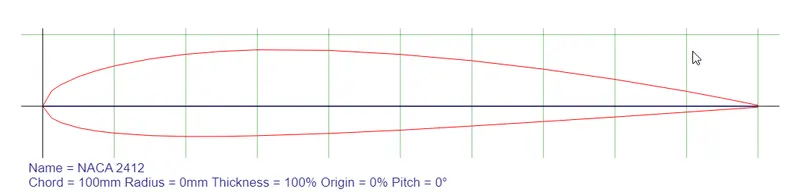
The vertices for NACA 2412 were taken from the airfoil tools website: NACA 2412 :
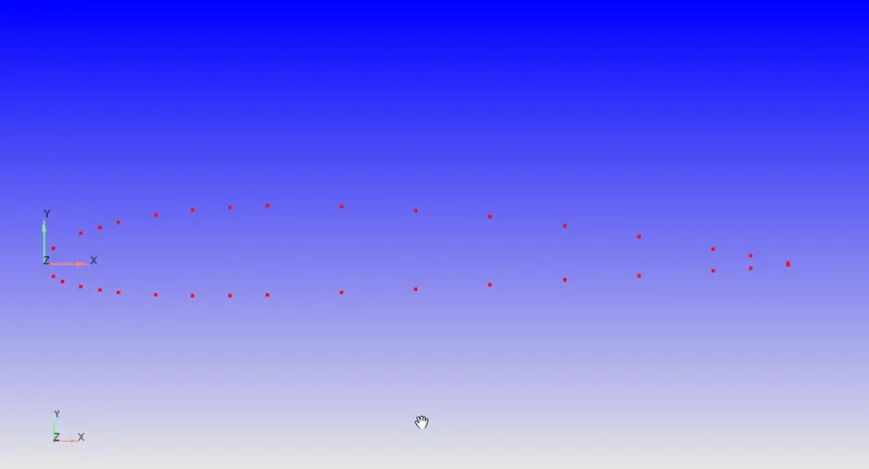
These vertices were manually plotted in Converge Studio:
Then vertices for a Wind Tunnel(2.4m x 1.25m) were also plotted and patched together using the patch tool in converge obtaining the profile:
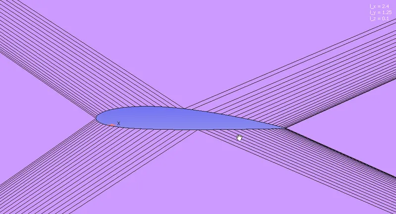
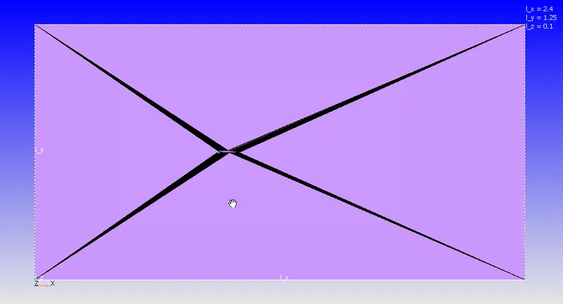
Once the profile was obtained, it was replicated along the z-axis using the copy command to set up the case.
BOUNDARY FLAGGING:
The Boundaries have been flagged as follows:
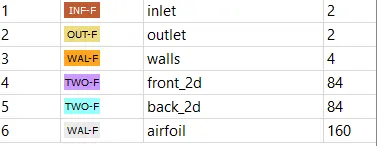
Inlet, Outlet and Walls:
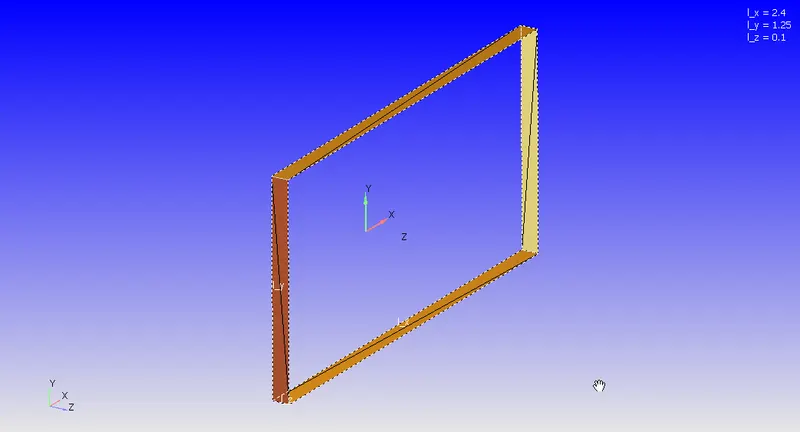
Front and Back 2D Boundaries:
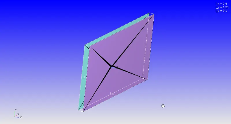
Airfoil:
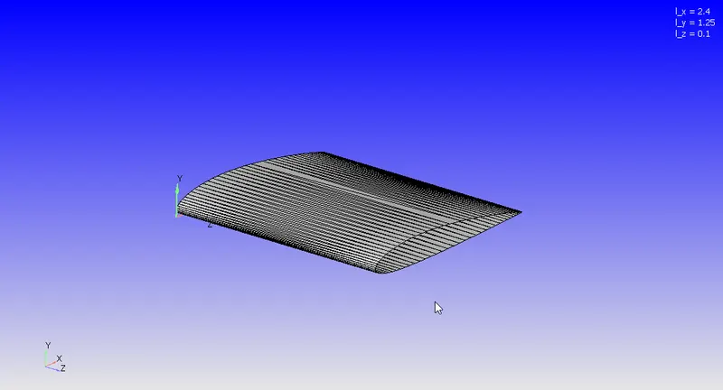
CASE SETUP:
Initial Conditions:
Initial conditions are Air at 298K and 1 atm Pressure at 31.42 m/s
Boundary Conditions:
| Inlet: |
The Reynolds Number is 200000. For Air at 298K and 1 atm, The velocity comes out to be 31.42 m/s. |
| Outlet: |
We have a Pressure outlet at 1 atm. |
| Walls: |
Walls are set to slip walls since the walls shouldn't affect the flow |
| Airfoil: |
Airfoil is set to the law of the wall with default parameters. |
Simulation Parameters:
This is a transient simulation:
Inlet Velocity = 31.42 m/s
Length of Wind Tunnel = 2.4 m
Flow Throw Time = 2.4/31.42 = 0.076 s
To Accurately Capture the Physics, its common practice to take 5 - 6 times the flow throw time as the simulation end time; hence end time is approximated as 0.4 s
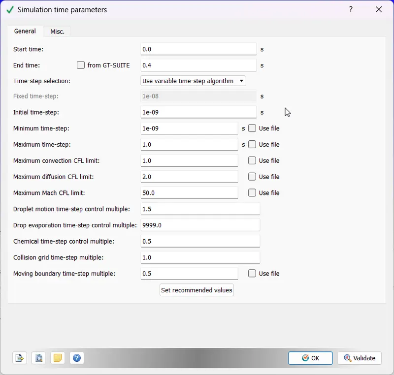
Solver Parameters:
We are using a Transient, Density-Based Solver. We will test each case of the angle of attack with RNG K-Epsilon and K-Omega SST Models with default values.
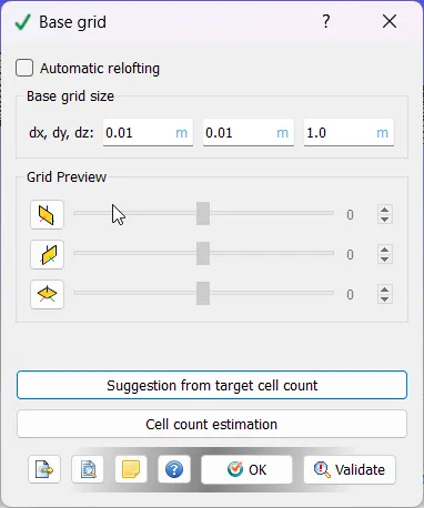
Mesh:
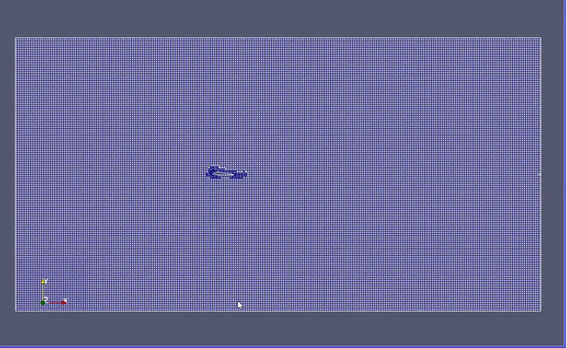
For general mesh, we are using a coarser mesh:
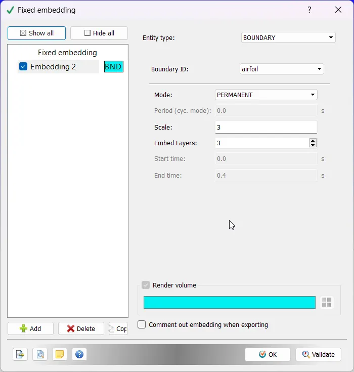
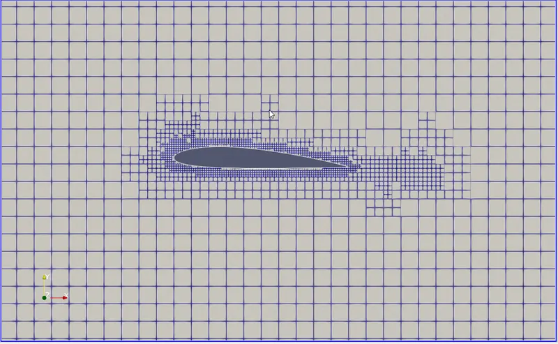
Next, we will be using a Fixed Embedded Mesh around the Airfoil to resolve the aerodynamic effects better:
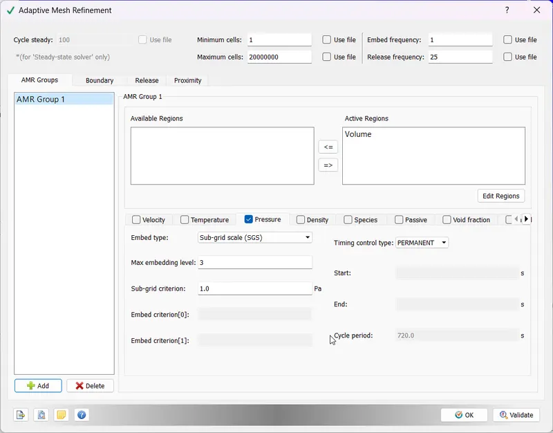
Lastly, we will use Pressure based AMR to capture the adverse pressure gradients:
Output Parameters:
We use the "Boundaries only" option to capture the boundary details and get a clear output of drag and lift forces on the airfoil.
RESULTS:
MESH:
ANGLE OF ATTACK = `1^o`
K-Epsilon Model:
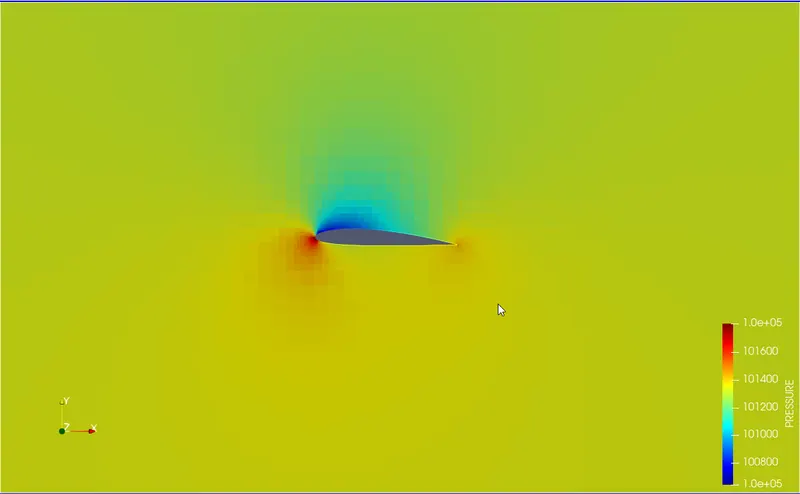
Pressure Contour:
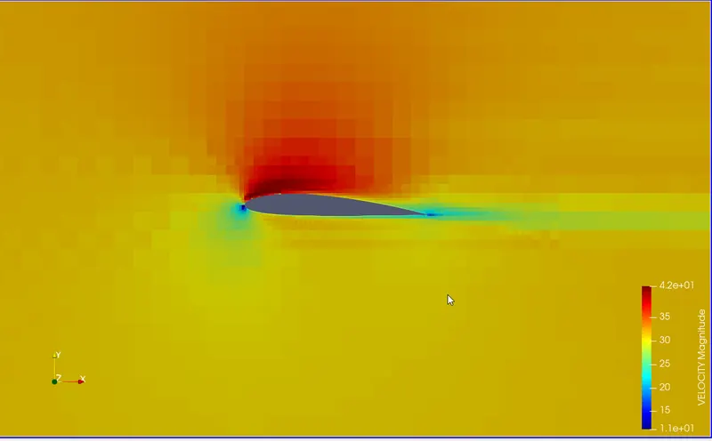
Velocity Contour:
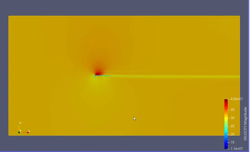
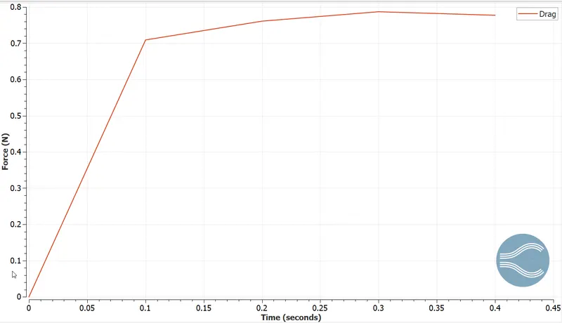
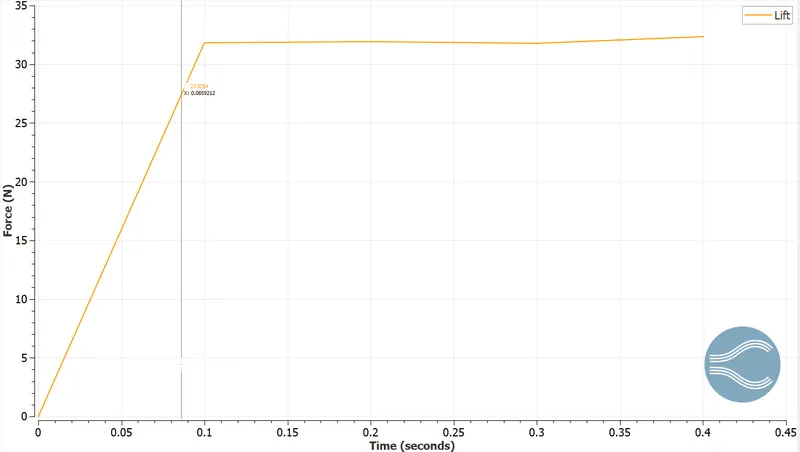
Drag and Lift:
K-Omega Model:
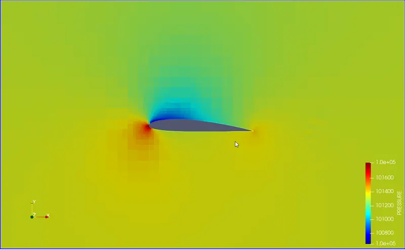
Pressure Contour:
Velocity Contour:
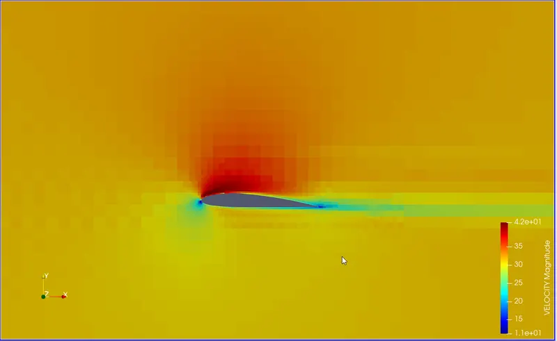
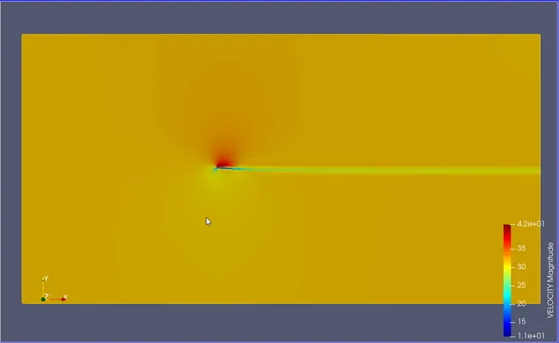
DRAG AND LIFT:
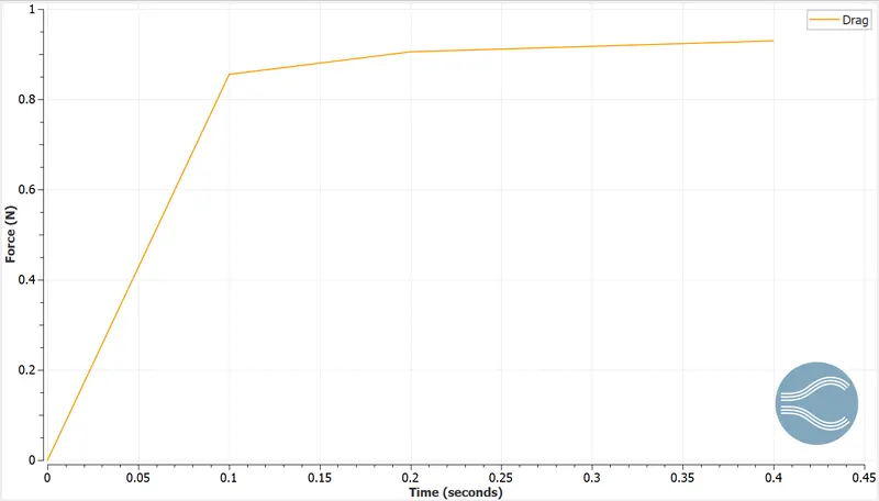
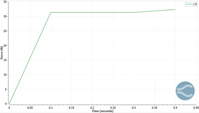
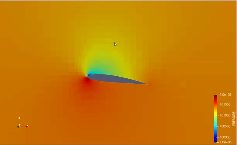
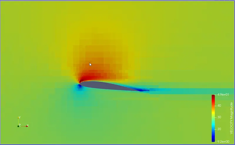
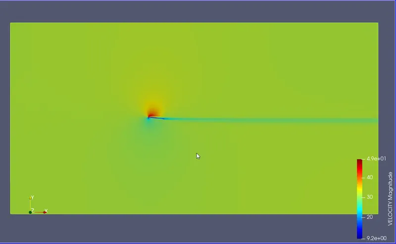
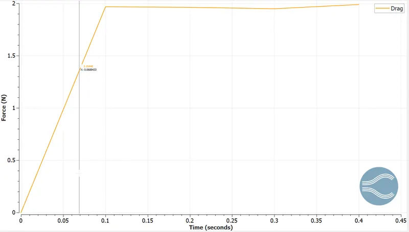
ANGLE OF ATTACK = `5^o`
K-Epsilon Model:
Pressure Contour:
Velocity Contour:
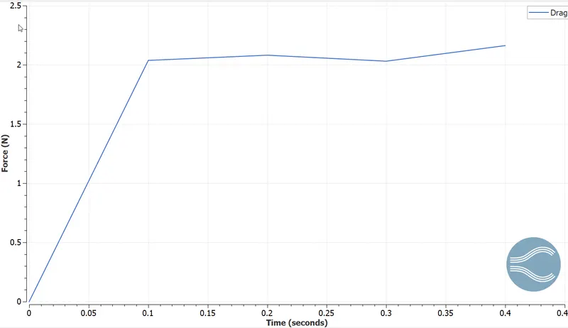
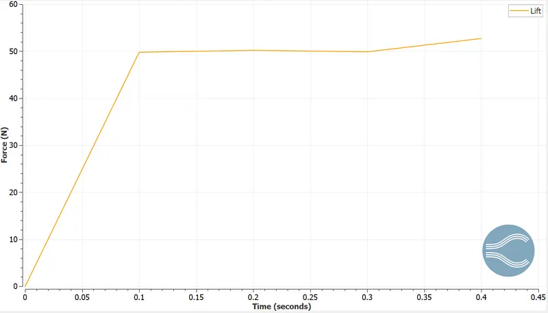
Drag and Lift:
K-Omega Model:
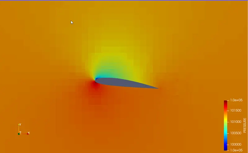
Pressure Contour:
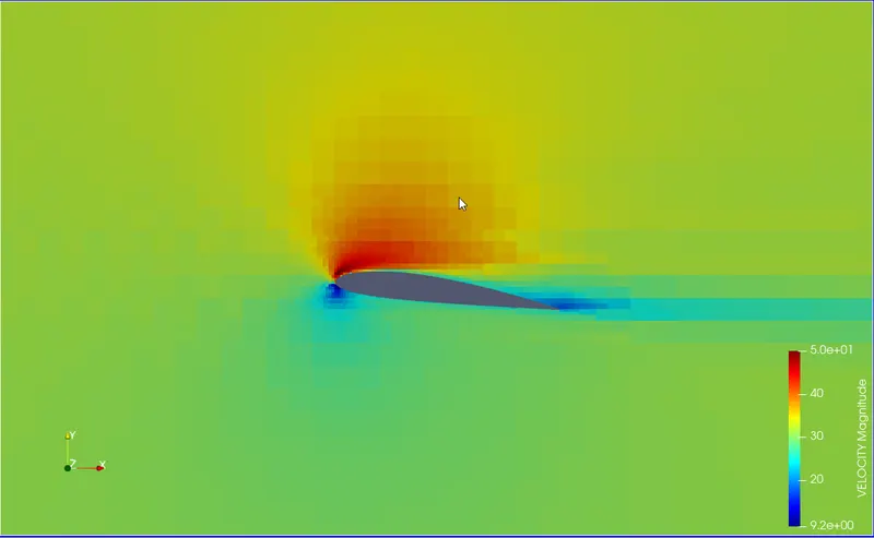
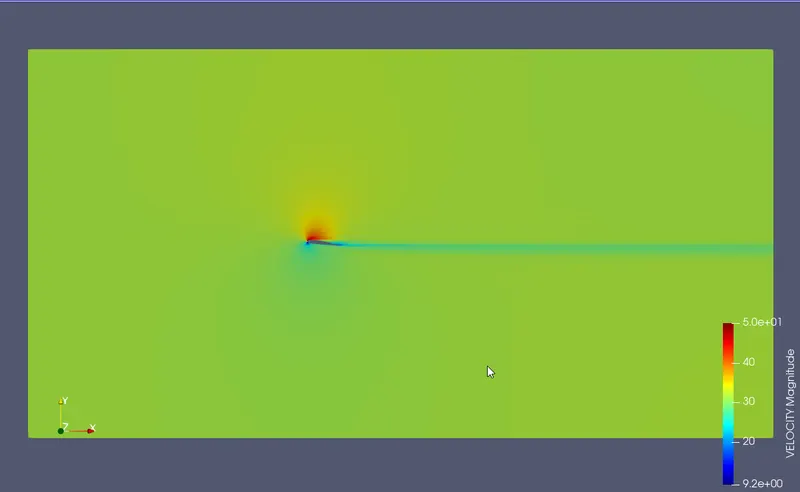
Velocity Contour:
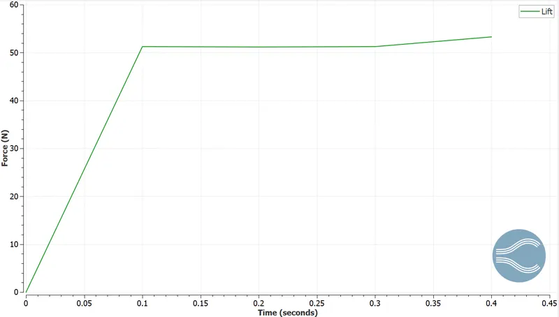
Drag and Lift:
ANGLE OF ATTACK = `10^o`
K-Epsilon Model:
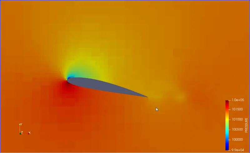
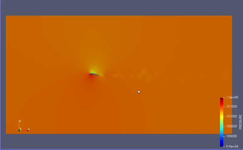
Pressure Contour:
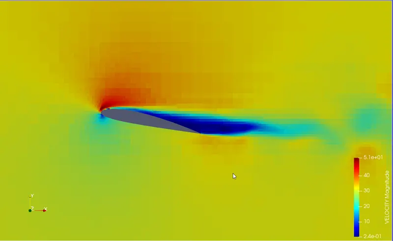
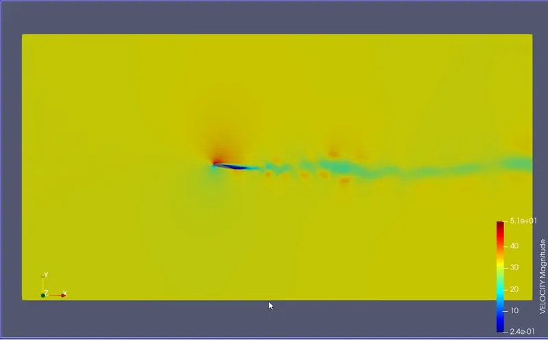
Velocity Contour:
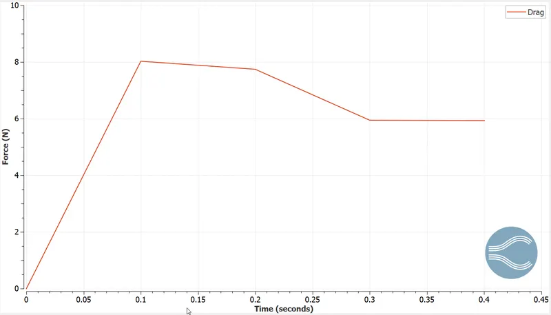
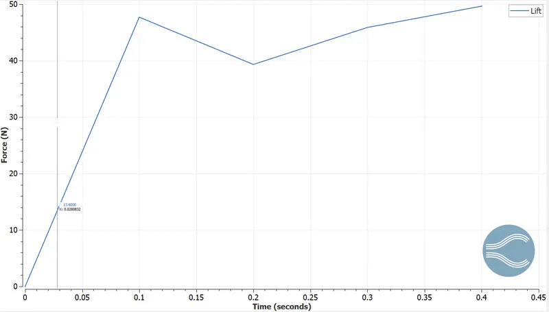
Drag and Lift:
K-Omega Model:
Pressure Contour:
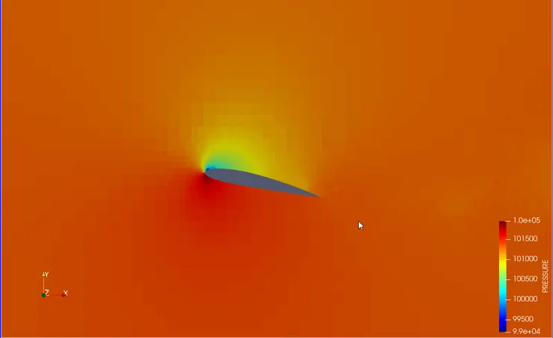
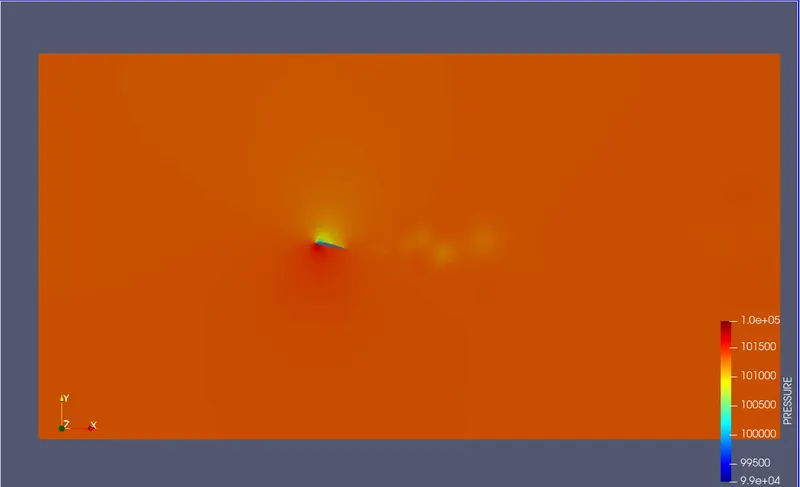
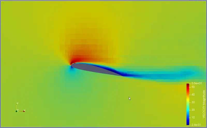
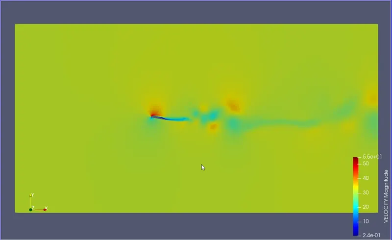
Velocity Contour:
Drag and Lift:
ANGLE OF ATTACK = `15^o`
K-Epsilon Model:
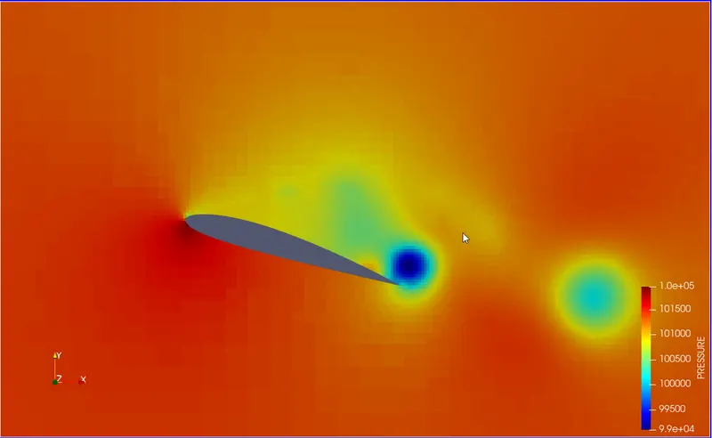
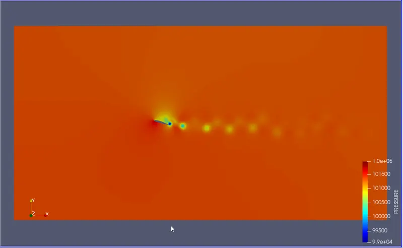
Pressure Contour:
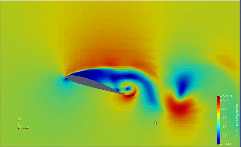
Velocity Contour:

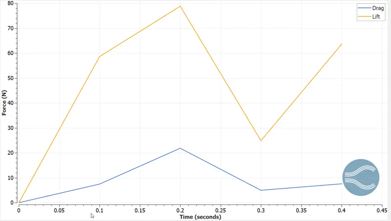
Drag and Lift:
K-Omega Model:
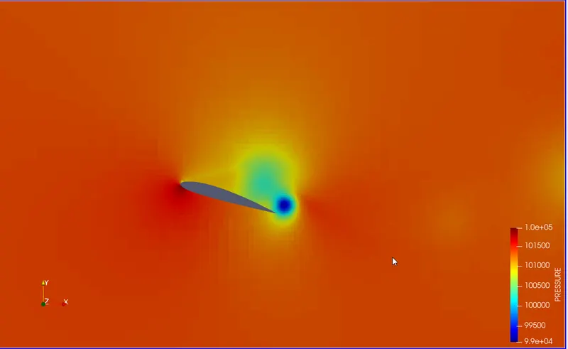
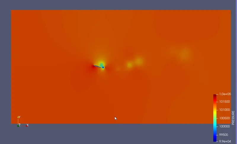
Pressure Contour:
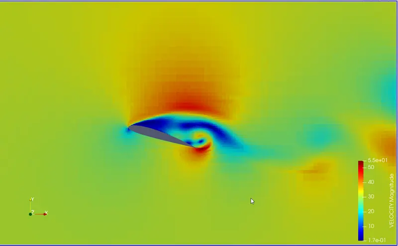
Velocity Contour:
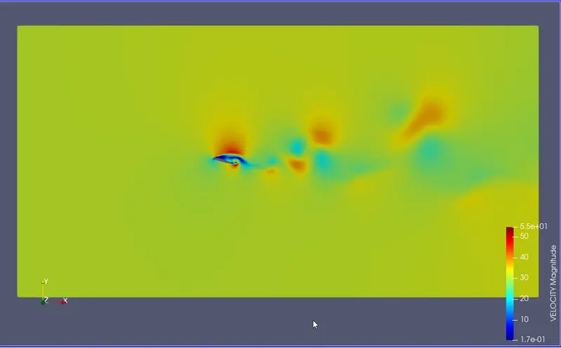
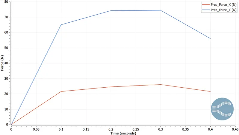
Drag and Lift:
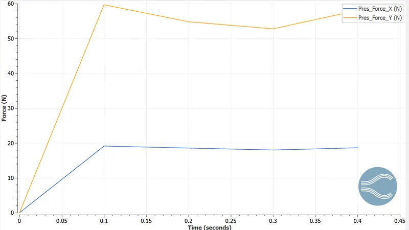
Lift Coefficient and Drag Coefficients:
To calculate the coefficients:
`C_(d"/"l) = (2*F_(d"/"l))/(rho*A*V^2)`
`rho =1.225` `kg"/"m^3` (Air at `25^o` C)
`V = 31.42` m/s
Since we are doing a 2D simulation, we will take the area as unity.
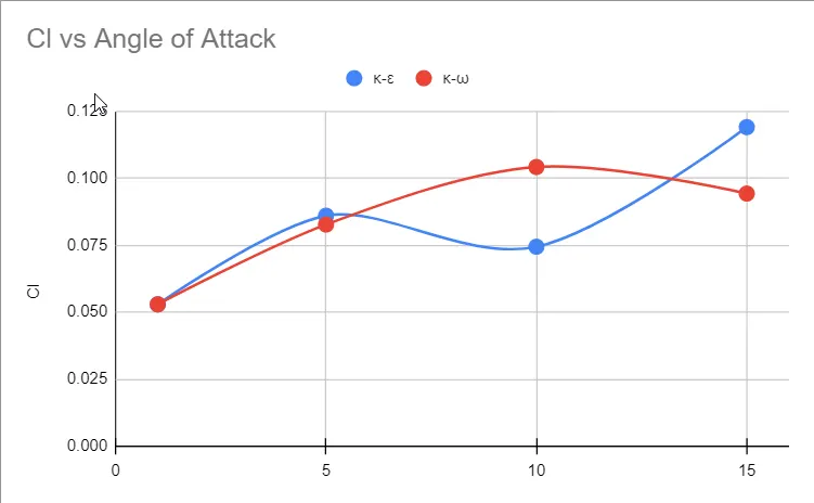
Lift Coefficient vs Angle of Attack:
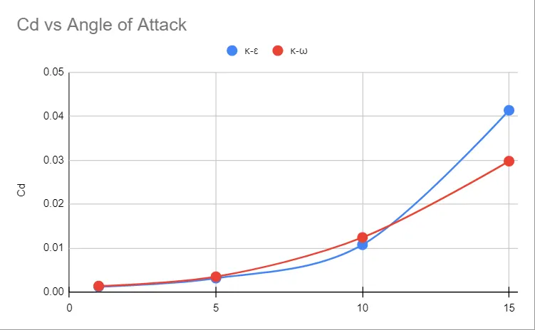
Drag Coefficient vs Angle of Attack:
INFERENCES:
- Through Various angles of attacks, we can see as we increase it, the turbulence increases, and there is a formation of vortices and eddies.
- The lift gradually increases with the angle of attack, peaking at `10^o` and then starts decreasing. This is due to vortex formations specified before.
- The drag increases with the angle of attack as the frontal area increases.
CONCLUSIONS:
- The K-omega SST model provides more accurate results, conforming to trends of experimental data published in Rodgers, E. J., H. C. Seetharam, and W. H. Wentz Jr. `1982^1`.
- This is due to the excellent near-wall performance capabilities of the k-omega model; this study also confirms the superior performance of the k-omega model in near-wall flows.
REFERENCES:
- Rodgers, E.J., Seetharam, H.C. and Wentz Jr, W.H., 1982. Experimental studies of flow separation of three airfoils at low speeds (No. AR-79-2). NASA.