Week 9 Machining with Planer Challenge
A planer is a type of metalworking machine tool that uses linear relative motion between the workpiece and a single point cutting tool to cut the work piece. A planer is similar to a shaper, but larger, and with workpiece moving, whereas in a shaper the cutting tool moves.
The most common applications of planers and shapers are linear-toolpath ones, such as:
- Generating accurate flat surfaces. (While not as precise as grinding, a planer can remove a tremendous amount of material in one pass with high accuracy.)
- Cutting slots (such as keyways).
- It is even possible to do work that might now be done by wire EDM in some cases. Starting from a drilled or cored hole, a planer with a boring-bar type tool can cut internal features that don't lend themselves to milling or boring (such as irregularly shaped holes with tight corners).
A typical metal cutting process by single point cutting tool. In this process, a wedge shaped tool moves relative to the work piece at an angle a. As the tool makes contact with the metal, it exerts pressure on it. Due to the pressure exerted by the tool tip, metal will shear in the form of chips on the shear plane. A chip is produced ahead of the cutting tool by deforming and shearing the material continuously, along the shear plane.
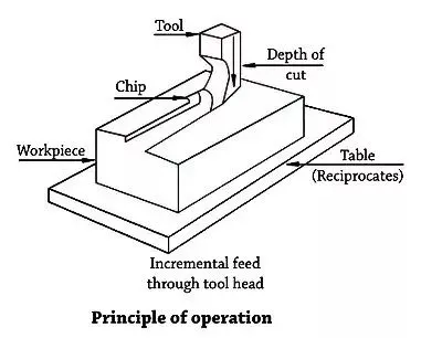
Objective:
The objective of this challenge is to an explicit dynamics simulation of the cutting operation on a workpiece Machining with Planer. This challenge inroduces the explicit dynamics approach in terms of structural simulations and the objective is to understand the settings and conditions to select explicit dynamics approach.
This simulation is done in 2 steps, i.e., velocity of the planer cutting tool as 20000 mm/s and 15000 mm/s.
Preprocessing for the analysis:
1. Geometry creation
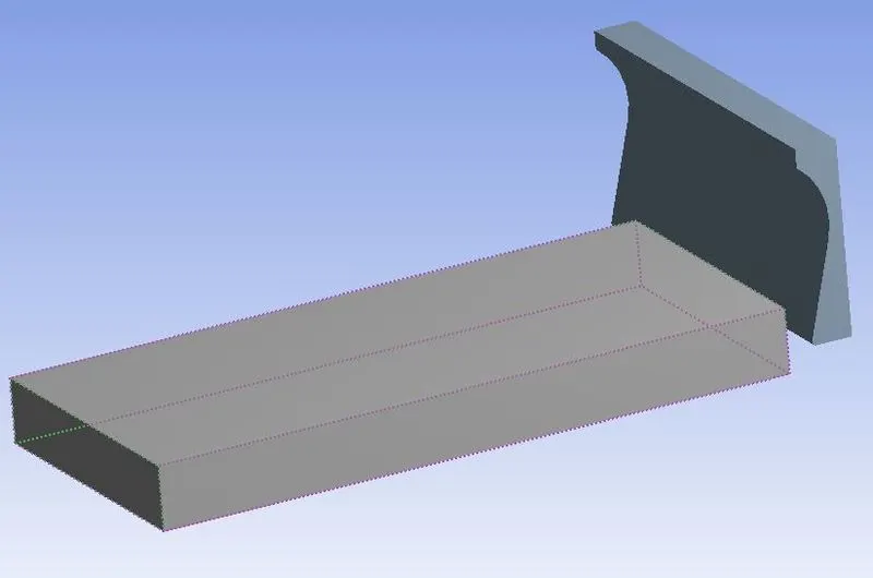
The model required for this challenge was obtained from the one given in the problem. The model is checked in modeler or spaceclaim for any irregularities in the model.
2. Material selection
From the 'Engineering data' section, steel 1006 material is added from the explict materials set of materials.
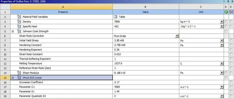
This material is assigned to the workpiece while the cutting tool bhavior is set to be "rigid".
3. Connections
Any default conacts made by the software is deleted as we don't have to study any relative motion between the planer tool and the workpiece.
Ansys software by default introduces the body-interaction tool which will create a frictionless contact between the two bodies
4. Meshing
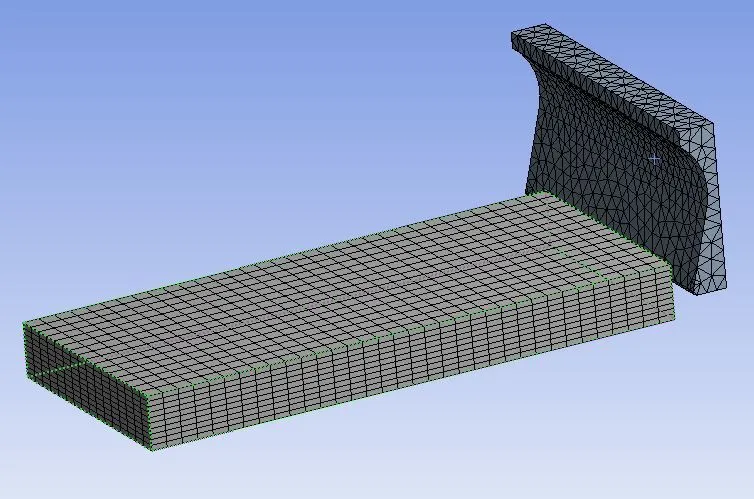
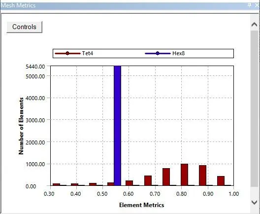
Since the planer body is rigid, it won't be meshed under automatic meshing protocol. Therefore, a mesh method is inserted in the module and the cutting tool is selected and assigned tetrahedral mesh.
To mesh the workpiece, a sizing component is inserted and the workpiece is meshed with respect to no. of divisions. The 4 vertical edges of the workpiece is selected and the 10 divisions along the vertical length are assigned. The software will extrapolate rest of the elements and create a structured mesh for the eintire workpiece.
5. Analysis settings
This analysis will be executed in one step only insce it will take a lot of computing power to execute multiple steps in explicit method. Explicit method of analysis is used only for simulating effects of short term events. An end timestep of 0.0075 is used and the rest of the conditions are left the unchanged.
The maximum, minimum and initial tine step are set to program controlled option as the steps must be lower than the courant number and the courant number changes for eahc particle with the mesh. It is compolicated to calculate the corant number and the software can calculate it hence, the time steps are set to "program controlled".
6. Loads and boundary conditions
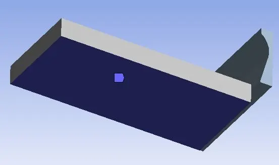
The worpiece needs to remain steadily while the planer tool does the planing operation, hence a fixed support condition is applied to one of the faces of the workpiece.
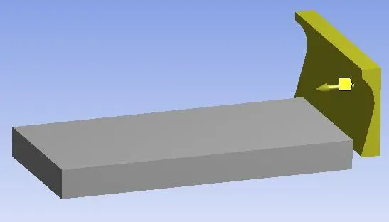
A velocity load is applied to the planer to simulate the curring action. Now this challenge involves 2 cases of simualtion with respect to velocity of the planer, therefore a parametric study was performed where planer velocity was kept as input parameter and the stress, deformation and temperature of the workpiece were kept as the output parameter.
Solution and postprocessing:
1. Total Deformation
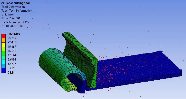
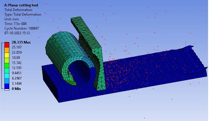
Since the velocity is reduced in case-2 (15000 mm/s), the planer tool covers a smaller distance in the gien time period. Hence, it can be observed that the simulation has stopped in the middle of the cutting operation. Also, the total deformation here matches in both cases since the cutting pattern is similar regardless of the speed of the tool.
2. Equivalent stress
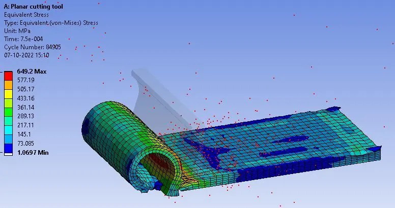
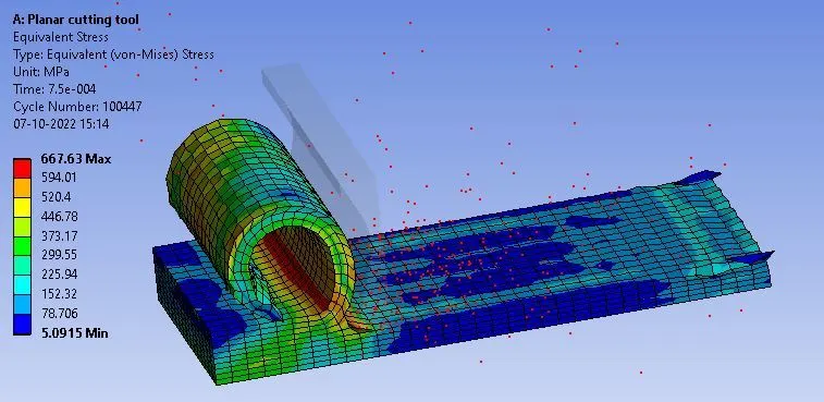
Since the planer is a rigid body, the software will not calculate the stresses acting on it. Hence, the planer tool can be seen as transparent in these results. The stresses developed in the worpiece must be the same regardless of the velovity of the tool since amount of force required to shear the workpiece remains the same. However, the stresses in the second case seem to be slightly higher as the cutting is not yet complete and plastic stresses are still present in that section of the workpiece.
3. Temperature
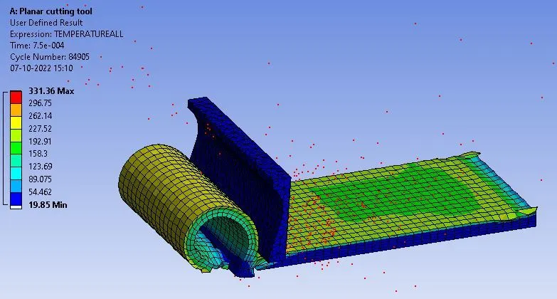
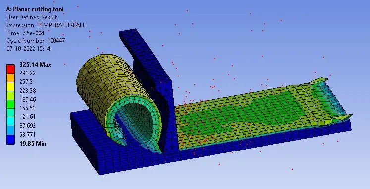
A higher speed creates higher friction and higher friction created high temperatures. Although the body contract between the two bodies in question here is frictionless, a slight dip in temperature is observed as the velocity of the planer decreases.
Results:
| Total Deformation (mm) | Equivalent stress (MPa) | Temperature (°C) | |
| Case-1 | 28.9 | 649.2 | 331 |
| Case-2 | 28.335 | 667.63 | 325 |