Writing a code to solve Air standard cycle (Otto cycle) in matlab
What is an air standard cycle?
The air standard cycle is a thermodynamic power cycle that converts heat energy into mechanical power by considering air as a working fluid with constant specific heat. In this cycle, the air is the only working fluid that goes through changes in its thermodynamic properties to convert heat into mechanical power. In this cycle, there is no internal energy generation through burning any fuel inside of the engine. The heat is externally added employing a heat exchanger & also it is rejected by using heat exchange to the sink. It is consists of a non-flow process. It means that a certain amount of air is continuously performing successive cycles. No intake or exhaust of air is permitted into the cycle. Hence it works as a closed cycle with no mass transfer. Working fluid air is considered an ideal gas with constant specific heat.
The Air standard cycle assumptions are as follows:-
- Air is considered as working fluid.
- Air has constant specific heat.
- Air behaves as an ideal gas
- All processes in the cycle are internally reversible.
- No internal heat generation takes place.
- Heat is added & rejected externally.
- The cycle is closed & processes are non-flow processes.
- There are no losses due to friction.
The internal combustion engine works on the sequence of separate process intake, compression, combustion, expansion and exhaust. It does not operate on thermodynamic cyclic because it involves an open system. The working fluid (fuel and air mixture) enters into the system in intake stroke and leaves it in the exhaust stroke. The working fluid does not complete a cyclic process. To analyze this system, we consider it as a close cycle where the working fluid brings at initial condition by injecting the new charge and exhausting the burned charge. However, the accurate analysis of an internal combustion engine is complicated. So to analyze the performance of an engine, it is idealized as a closed air cycle in which only air is the working fluid and heat is supplied by the reservoir.
Otto Cycle:-
The Otto cycle is an ideal thermodynamic air standard cycle consisting of two constant volume processes and two isentropic processes.
The Otto cycle is the working cycle for the petrol or SI engine and operates at a comparatively lower compression ratio. Hence, engines working on the Otto cycle are light in weight. In this cycle, the heat addition and heat rejection take place at a constant volume.
Following are the PV and TS diagrams for the otto cycle,
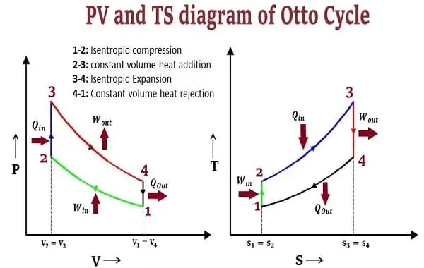
The Otto cycle consists of the following processes,
Process 1-2:- Isentropic compression
Process 2-3:- Constant volume heat addition
Process 3-4:- Isentropic expansion
Process 4-1:- Constant volume heat rejection
The working of the SI engine is based on the principle of the otto cycle. The working of an SI engine based on the Otto cycle can be explained below.
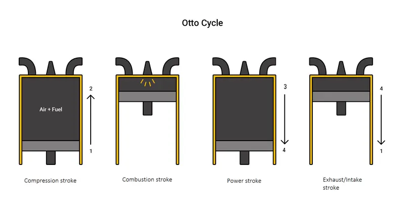
The following describes what occurs during each step on the PV diagram, in which the combustion of the working fluid—gasoline and air (oxygen), changes the motion in the piston:
Process 1 to 2: This stage begins with the compression stroke of the engine with the closing of the intake valve. Between Stage 1 and Stage 2, the piston moves back into the cylinder, the gas volume decreases, and the pressure increases because of the work done on the gas by the piston—however, no heat is exchanged. In terms of thermodynamics, this is referred to as an adiabatic process. When the cycle reaches stage 2, that is when the fuel is met by the spark plug to be ignited.
Process 2 to 3: Stage 2 is the beginning of the combustion of the fuel/air mixture. The combustion occurs very quickly and the volume remains constant. Heat is released during combustion which increases both the temperature and the pressure, according to the equation of state. In terms of thermodynamics, this is referred to as an isochoric process.
Process 3 to 4: Stage 3 begins the power stroke of the engine. Between Stage 3 and Stage 4, the piston is driven towards the crankshaft, the volume is increased, and the pressure falls due to work done by the gas on the piston. The thermal energy in the chamber as a result of combustion is used to do work on the piston—which pushes the piston down—increasing the volume of the chamber. This is known as the power stroke because in this stage the thermal energy is turned into motion to power the machine or vehicle.
Process 4 to 1:At Stage 4 the exhaust valve is opened and the residual heat in the gas is exchanged with the surroundings. The volume remains constant and the pressure adjusts back to atmospheric condition. At the end of the exhaust stroke, conditions return to Stage 1 and the process repeats itself.
Thermal efficiency:
Thermal efficiency of an air standard cycle is given by,
`η_(th) = W_t/Q_s`
`W_t` = Total work done by the fluid = `W_(3-4) - W_(1-2)`.
`Q_s` = Heat supplied.
For an Otto cycle efficiency can be given as,
`eta_(th)=1-(V_2 / V_1)^(gamma-1) = 1-(1/cr)^(gamma-1)`
cr- compression ratio of the engine.
We shall now attempt to solve an otto cycle via Matlab coding.
- Algorithm followed for the Matlab program:
Let us see step by step how to design a code in Matlab to obtain a P-V diagram for the otto cycle with given parameters.
At the start of programming, we shall assume that we have the initial state of working fluid i.e. Pressure and temperature at stage 1 (`P_1, T_1`). volume at stage one (`V_1`) can be found out with help of engine parameters like bore of the cylinder, stroke length of the piston, length of connecting rod, etc. In fact, the volume for any process can be calculated if we know all the above variables along with the crank angle at the start and the end of the stroke. To trace volume occupied at any point in the cycle, a function can be written so that an accurate curve can be created for the P-V diagram. The formula for tracing volume at any point in the cycle is given in the literature and can be represented as,
`V/V_c= 1-0.5*(cr-1)*(R+1-cos(theta)-(R^2-sin^2(theta))^0.5)` ------------------------------------(1)
This will be further explained in the steps below.
- Creation of volume tracing function
- The volume tracing formula in (1) will be used to create this function. Elaborating on the formula, the terms in the formula are,
V- Volume that is being traced
`V_c = V_s/(cr-1)` - clearance volume
`V_s`= `(pi/4)*(d)^2*(l)` - Swept volume
d - bore diameter l- stroke length
`a= l/2` - crank radius L- length of connecting rod
`R=L/a`
`theta`- range of values of crank angle.
- Function V is defined as a function with `theta`and `V` as variables and the rest as input parameters. The inputs for this function include bore of the cylinder, stroke length of the piston, length of connecting rod, and value of `theta`.
2. Code to plot Otto cycle
I. clear all - Removes items from workspace, freeing up system memory.
close all - Closes all figures except those listed by the user.
clc - clears all data from the command window.
II. All inputs to the function as well the code are listed including values of bore of the cylinder, stroke length of the piston, length of connecting, pressure and temperature of stage 1, temperature of stage 3 and the value of gamma.
III. `V_c` & `V_s` are calculated.
IV. Values of state parameters at each stage is calculated viz. p2, p3, p4, t2, t4, v1, v2, v3, v4.
V. volume trace function is called to find the volume at any point on the P-V curve by the following syntax,
V_comp = engine_kinematics(bore, stroke, conn_rod, cr, 180, 0);VI. Since for an adiabatic process,
`P*V^gamma = c`
Pressure at any point can be calculated as well.
VII. All values of P & V are plotted and joined to form a curve. the plot is labeled, titled and a legend is included to properly distinguish between every process.
VIII. Each point is labeled using the 'text' command and finally the efficiency is calculated and printed.
- Code developed to solve Otto cycle
- Volume tracing function for otto cycle
function [v] = engine_kinematics(bore, stroke, conn_rod, cr, start_angle, end_angle)

%crank radius = stroke/2
a = stroke/2;

%connecting rod length/ con rod radius
R=conn_rod/a;

%swept & clearance volume calculation
Vs= (pi/4)*bore^2*stroke;
Vc= Vs/(cr-1);

%crank angle
theta = linspace(start_angle, end_angle, 50);

%solving equation for volume tracing as per standard formula
%V/Vc = 1+ 1/2(cr-1)*(R+1-cos(theta)-(R^2 - sin(theta)^2)^1/2);
term1= (cr-1)*0.5;
term2= R+1-cosd(theta);
term3= (R^2-sind(theta).^2).^0.5;
v = (1+term1*(term2-term3))*Vc;
end
2. Code to plot Otto cycle
clear all
close all
clc

%inputs
p1 = 101325     %state 1 pressure in N/mm2
t1 = 500;          %state 1 temp. in K
t3 = 2000;        %state 3 temp. in K
gamma = 1.4;   %ratio of heat capacities

%inputs to calculate volume
bore = 0.15;
stroke = 0.15;
conn_rod=0.2;
cr=12;

%swept & clearance volume calculation
Vs= (pi/4)*bore^2*stroke;
%Total vol V =Vs+Vc
%comression ratio cr = V/Vc = (Vs+Vc)/Vc
% Vc= Vs/(cr-1)
Vc= Vs/(cr-1);

%calculating state parameters
v1= Vs+Vc
v2=Vc

%State 2 Parameters(Isentropic compression)

%p1*v1^gamma = p2*v2^gamma;
%p2 = p1* (v1/v2)^gamma;
p2=p1*cr^gamma

%p1*v1/t1 = p2*v2/t2
t2 = ((p2*v2)/(p1*v1))*t1;

% In isentropic processes, P*V^gamma = constant = c
c=p1*v1^gamma;
%functioned defined earlier, tracks variation in coolume throughout the
%process from v1 to v2
V_comp = engine_kinematics(bore, stroke, conn_rod, cr, 180, 0);
%To track variation in pressure at every point from p1 to p2
P_comp = c./V_comp.^gamma;

%state3 parameters(Isochoric heat addition)
v3 = v2

% for isochoric process, p2/t2 = p3/t3 and t3 is given
p3 = p2*t3/t2

c=p3*v3^gamma;
V_exp = engine_kinematics(bore, stroke, conn_rod, cr, 0, 180);
P_exp = c./V_exp.^gamma;

%state 4 parameters (Isentropic expamnsion)
v4 = v1
p4 = p3/cr^gamma
t4 = ((p4*v4)/(p3*v3))*t3;

%plotting curve
hold on
plot (v1, p1, '*', 'Color','r');
plot (V_comp, P_comp, 'LineWidth',2, 'Color','c');
plot (v2, p2, '*', 'Color','b');
plot (v3, p3, '*', 'Color','g');
plot (V_exp, P_exp,'LineWidth',2,'Color','y');
plot (v4, p4, '*', 'Color','k');

%To join the two sientropic cycles on the plot
plot ([v2 v3], [p2 p3], [v1 v4], [p1 p4], 'LineWidth',2, 'Color', 'm');


xlabel ('Volume (m^3)', 'FontSize',12, 'FontWeight','bold','Color',[0.22 0.34 0.45]);
ylabel ('Pressure (N/mm^2)','Fontsize',12, 'FontWeight','bold','Color',[0.22 0.34 0.45]);
title ('P-V diagram of Otto cycle', 'BackgroundColor', 'w', 'Color',[0.22 0.34 0.45]);


legend ('','Isentropic compression','', '','Isentropic expansion','' ,'Isochoric heat excahnge proceess')
%Includes all plots in the legend. The empty spaces correspond to the points
%corresponding to 4 states in the cycle in the plots of the P-V diagram


%To include text to mark poisitons of P-V poarameters for various states in the P-V plot
%First two values in the command correspond to the co-ordinates to place
%the text found by observing the output of the code
text (0.0030, 101325,'P1, V1');
text (0.00025,3285400, 'P2, V2');
text (0.00025, 4863700,'P3, V3');
text (0.003, 301325,'P4, V4');

%calculation of thermal efficiency
%eta_th = 1- (v2/v1)^(gamma-1) = 1- (1/cr)^(gamma-1)
eta_th = (1- (1/cr)^(gamma-1))*100;

%prints given output with the calculated value of thermal efficiency up to two decimal places
fprintf ('The thermal efficiency of present Otto cycle is %.2f\n', eta_th)- Error faced while the development of code
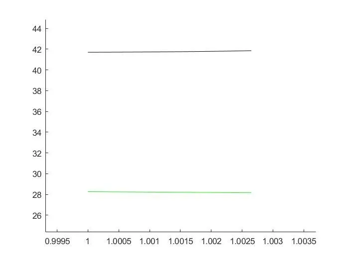
As can be observed from the plot, it is evident that the value of pressure doesn't change with respect to volume as expected. There were minor variations in the value of pressure which were observed after printing the value of Pressure in the command window, however, the curve wasn't as expected.
Steps taken to overcome error:
Upon detailed study of all the commands in the code, it was observed that there was a syntax error in the function 'engine_kinematics' wherein the volume tracing equation,
V/Vc = 1+ 1/2(cr-1)*(R+1-cos(theta)-(R^2 - sin(theta)^2)^1/2);
This equation was written as,
V/Vc = 1+ 1/2(cr-1)*(R+1-cos(theta)-(R^2 - sin(theta)^2)^1/2 ;
Notice the missing end of the bracket. due to the missing bracket end, the value of V was not being computed properly and resulted in wrong values of pressure.
b. 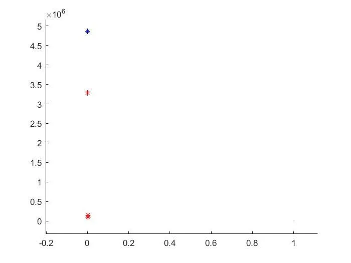
It can be observed in the attached figure that the wrong values of volume are being considered and plotted in the plot. The volume seems to be assuming a value of zero and only pressure is varying and taking the correct values as was confirmed from the command window and manual calculations of a solution of the standard equation.
Steps taken to overcome error:
Upon detailed study of all the commands in the code, it was observed that there was a syntax error in the function 'engine_kinematics' wherein the volume tracing equation,
V/Vc = 1+ 1/2(cr-1)*(R+1-cos(theta)-(R^2 - sin(theta)^2)^1/2);
The current error and the above error occurred simultaneously and were the result of the program taking garbage value from the function 'engine_kinematics'.
As soon as the mistake was identified and fixed, both these errors were resolved.
c. 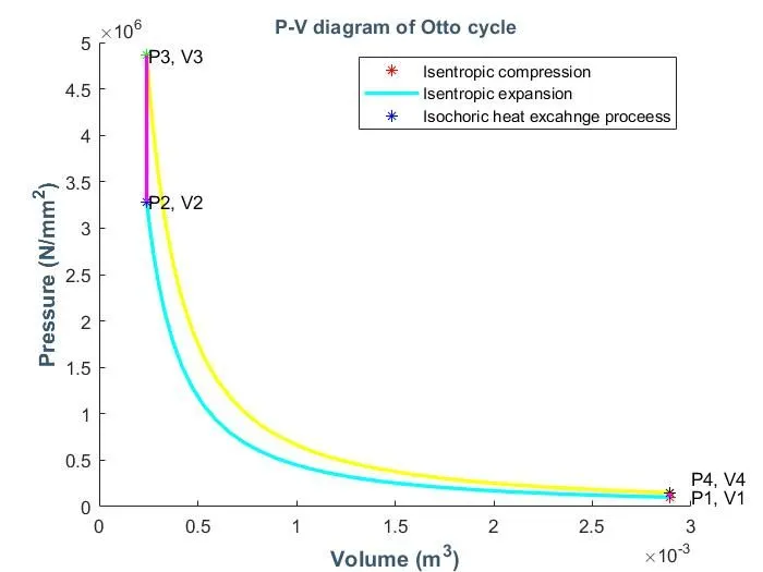
From the above image, the legend needs to be observed. It is evident that the intention was to highlight the curves in the plot, yet the points were also being highlighted.
Steps taken to overcome error:
It was quickly identified that the legend command includes all the entities in the plot be it a point of a curve, the code was modified from an earlier version,
legend ('Isentropic compression','Isentropic expansion','Isochoric heat addition');
to the current version of,
legend ('','Isentropic compression','', '','Isentropic expansion','' ,'Isochoric heat addition', 'Isochoric heat rejection');
- Output
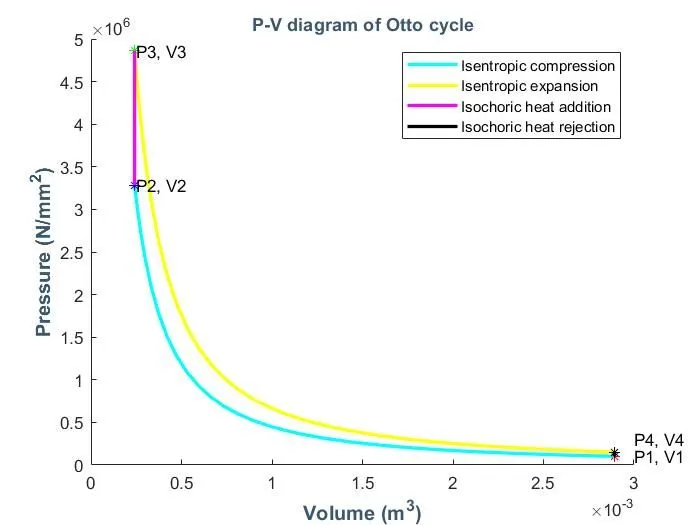
- The P-V curve of the Otto cycle is thus plotted using the Matlab program.

2. The efficiency of the otto cycle is calculated to be 62.9%