Week - 4
- Implement control logic of a “washing machine” using Stateflow as per given sequence:
- If the power supply is available, the system gets activated
- If the Water supply is not available, stop the process & indicate through LED
- Soaking time should be 200s followed by Washing time of 100s.
- Then rinsing happens for next 20s & dryer runs for 50s
After all the processes have completed turn on the finished LED
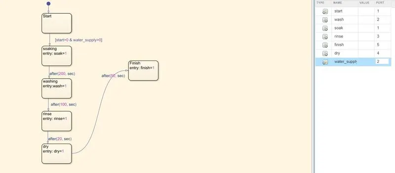
The control logic for a washing machine is very straighforward. If the power switch is 'ON', the machine starts with soaking for 200 s then washing for 100 s then followed by rinsing and drying for 20s and 50 s respectively.
The protocol for stateflow chart of a washing machine is as follows:
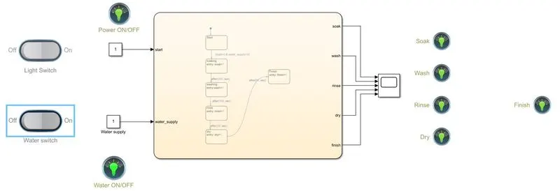
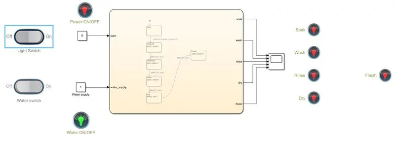
- A light switch is used to provide input for power. An input of zero indicates lack of power and lits the 'RED' lamp and if the lamp is switced 'ON', the start lamp is lit 'GREEN'.
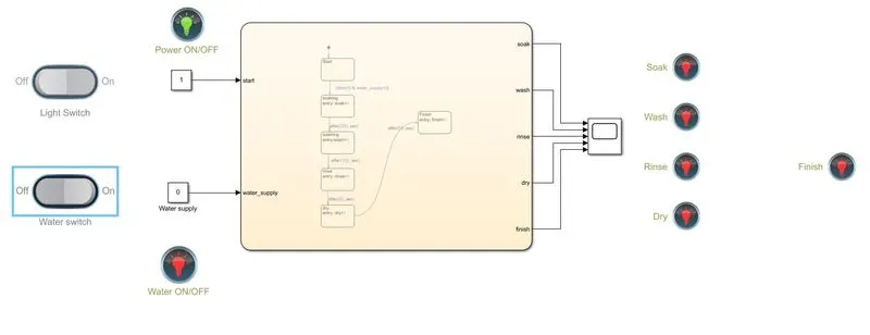
- If the water supply is cut off, theoperation stops and 'RED' light is indicated on the water supply switch.
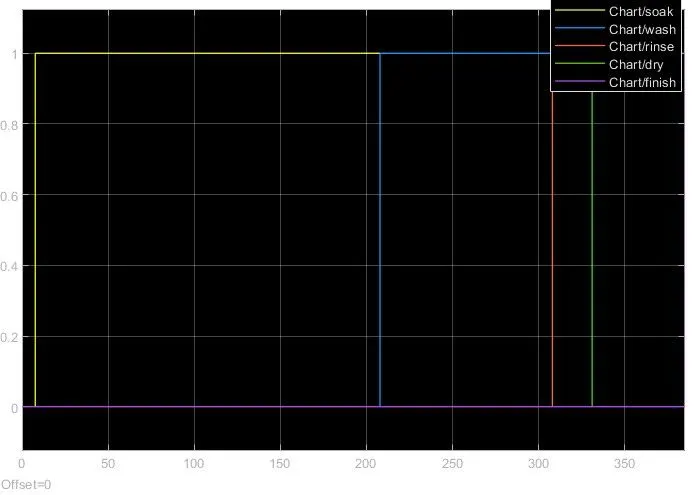
- If the both the switch are 'ON', the machine starts and starts soaking. The soaking value is considered as output for the indication lamp.
- With a delay of 200s, the machine starts washing for 100s. wash is used as output for the indication lamp.
- At the end of 100s, the machine starts rinsing for 20s and uses this delay of 20s to then move on to drying. rinse and dry are used as outputs for the indication lamp.
- After 'drying' for 50s, the machine finishes the washing cycle and the finished lamp is lit.
- Finish is used as an output for the finisnhed indicator light.
- All the processes are connected to the same scope block to study the data on each stage of the cycle.
The stateflow chart for a washing machine is as follows,
The complete logical flowchart for the washing machine is given below,
Results:
- Power switched 'OFF'
- Water switched 'OFF'
- Water and power switched 'ON'
II. Make a Simulink chart for the “Gear shift” logic as per below conditions:
Speed Range(kmph) Gear
0 to 15 1
16 to 25 2
26 to 40 3
41 to 60 4
Above 61 5
Give speed input while the simulation is running & display the gear number.
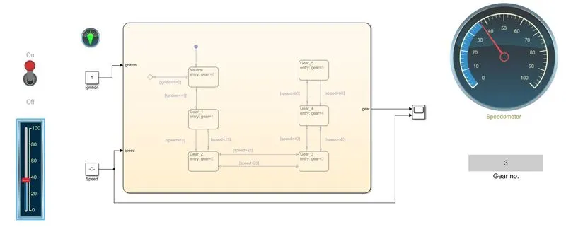
A gear box is a part of the transmission system of an automobile. A general rule with gears is that the higher the gear, the higher the rpm you get. This is important to run the automobile at higher speeds.
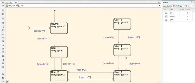
The rules of operation of the gearbox are given in the problem statement above. In present case, one particular state of the chart is governed by 2 states i.e upper and lower speed of the automobile. As soon as the automobile reaches a certain minimum speed, the gear must shift to particular value. As soon it reaches a specified maximum speed, the gear must shift to a higher gear and as it reaches below a specified miunimum speed, it must revert to a lower gear. Based on this philosophy, the stateflow chart of the gear shift meachanism is designed below.
The protocol for stateflow chart of a gear shift system is as follows:
1. The ignition switch is connected to a constant which is taken as an input for the stateflow chart. The ignition is indicated by a lamp turning 'GREEN' when the switch is 'ON'.
2. A veritcal slider is used as a throttle for speed. The vertical slider is connected to a constant input for speed. The speed is also displayed on a speedometer
3. When the ignition is off, the start lamp indicates so by switching the 'RED' light on. When the ignotion is turned 'ON', the chart moves to neutral gear and if the speed is more than 0 and less than 15 km/hr it shifts to gear one.
4. The output 'gear' is connected to a display and the gear is displayed on it depending on the speed given as input.
5. Each gear is considered as a separate state. Each state is governed by two conditions, one with minimum speed and one with maximum speed for a specific gear.
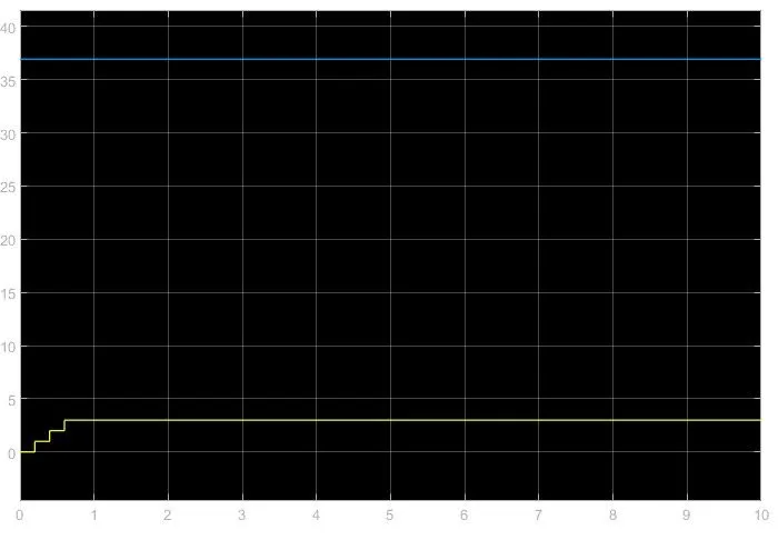
6. The output 'gear' is connected to a scope and a display. The speed input is also connected to the scope. A scope will show how the gear changes with speed.
The stateflow chart for a gear shift is as follows,
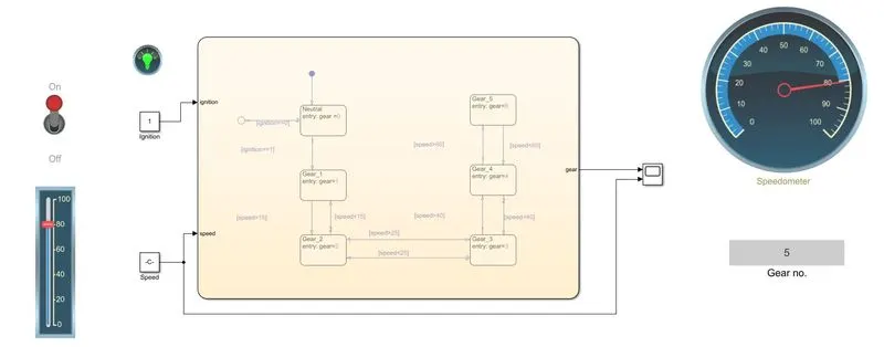
Results:
1. Ignition 'OFF'
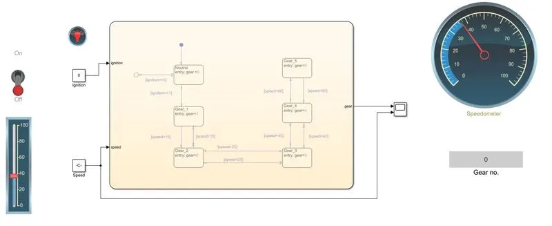
2. Ignition 'ON' with speed 38 kmph