Week 9-Creation of 1D Connectors Challenge
To create various types of 1-D connectors using hyperworks for given component
Aim :- To mesh the component withing given quality parameters and connect all the parts with following connector
- Right_Rail_2 & Front_truss_1:- Seam-Quad( angled + capped + L )
- Left_Rail_2 & Front_truss_1:- Quad elements
- Front_truss_2, Front_truss_1 & Right_Rail_1:- Spot weld with 3 Layers and 5 mm Diameter
- Front_truss_2, Front_truss_1 & Left_Rail_1:- Hexa (Adhesive)
- Rear_truss_2 & Right_Rail_2:- Bolt Connector
- Rear_truss_2 & Left_Rail_2:- Bolt Connector
- Right_Rail_1 & Right_Rail_2:- Spot-weld with Rigid Elements
- Left_Rail_1 & Left_Rail_2:- Spot-weld with Spring Elements
- Rest all the component left Join them with suitable connectors
Software used :- Hyperworks 2020 – student version
Methodology :-
- Import given CAD model to hyperworks.
- Check and rectify geometric errors.
- Meshing as per given quality criteria.
- Establishing connections as mentioned in given problem statement.
- Realizing and debugging connections.
Procedure :-
- Import given CAD model to hyperworks :- Import given model into hyperworks, given model is in .hm format so we can directly open the model.
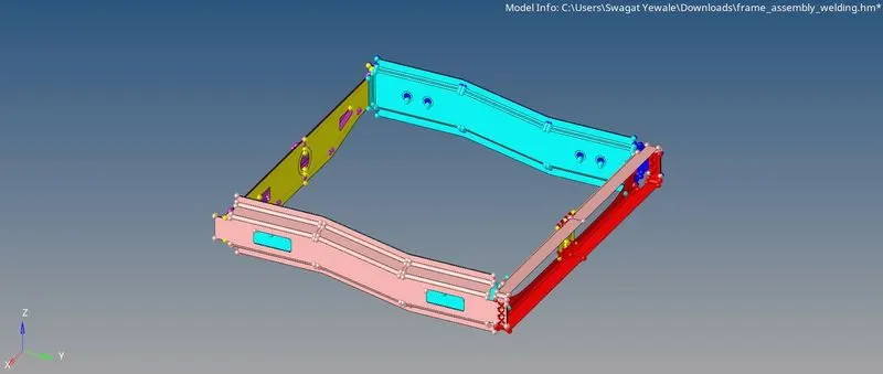
- Check and rectify geometric errors :- After importing model gets geometric errors like surface missing, surface duplication, etc. so we have to cleanup geometric errors. These errors are cleaned by manually or automatically by Geometric > autoclean > select target element leangth up > select model > autocleanup option option.
Here, no any errors are found so we can move further.
- Meshing as per given quality criteria :- Here, I used automesh for meshing. Before meshing need to assigned the quality parameters by Toolbar > Preference > Criteria file settings > Assign the given values as shown in image below.
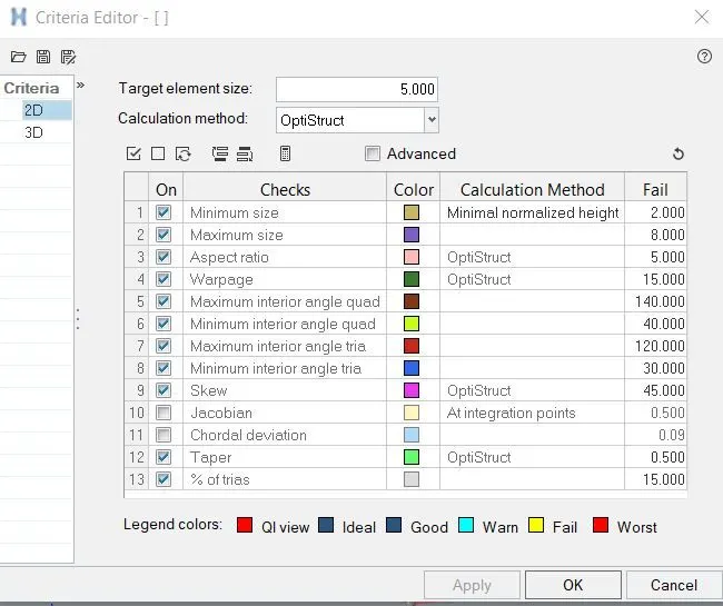
Mesh the surface part by part by using 2D > Automesh > select surface > select mesh size 5 mm > mesh option as shown in image below. After meshing need to check elements which are violating thresholds, for that go to 2D > Quality index option it will highlight the elements which are not as per assigned quality criteria. For eliminating these elements need to use 2D > Quality index > Cleaning tool option in that we can use smooth, element optimization, node optimization, place node, drag tria element, combine tria element, etc options.
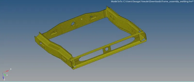
- Establishing connections as mentioned in given problem statement.
- Right_Rail_2 & Front_truss_1:- Seam-Quad( angled + capped + L ) :- Visible only FE model of right rail 2 and front truss 1 and establish angled + capped + L connection by following steps –
- Open Connectors panel in 2D menu.
- Select components to be connected.
- Select Seam-Quad( angled + capped + L ) option.
- Select nodes path
- Select components to be connected
- Define proper tolerance and click on create option the connection is established

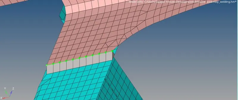
- 2. Left_Rail_2 & Front_truss_1:- Quad elements :- Hide all components except Left_Rail_2 & Front_truss_1 and deploy Quad elements connection by following steps –
- Select seam weld option in connector panel
- Select nodes by path for connectors to be deployed
- Select component
- Select weld type as quad element
- Define tolerance as 20 and click on create option and connection is established

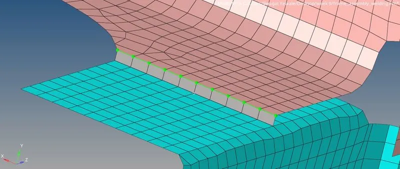
- Front_truss_2, Front_truss_1 & Right_Rail_1:- Spot weld with 3 Layers and 5 mm Diameter :- Hide all components except Front_truss_2, Front_truss_1 & Right_Rail_1 and deploy Spot weld with 3 Layers and 5 mm connection by following steps –
- Select spot weld option in connector type
- Select nodes by path
- Select components to be connected
- Select spot weld type as weld
- Define tolerance as 10
- Define diameter as 5mm and layers as 3 and click on create it will established connection

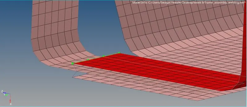
- Front_truss_2, Front_truss_1 & Left_Rail_1:- Hexa (Adhesive) :- Hide all components except Front_truss_2, Front_truss_1 & Left_Rail_1 and deploy Hexa (Adhesive) connection by following steps –
- Select seam weld option in connector type
- Select nodes by path
- Select components to be connected
- Select type as Hexa (Adhesive)
- Click on create tab it will generate adhesive connection.

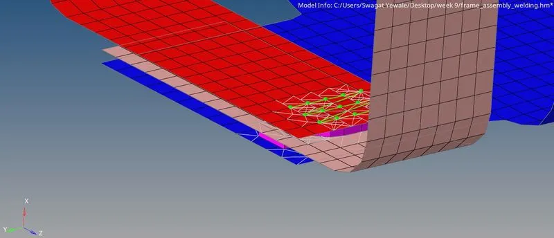
- Rear_truss_2 & Right_Rail_2:- Bolt Connector :- Hide all components except Rear_truss_2 & Right_Rail_2and deploy bolt connection by following steps –
- Select bolt option in connector type
- Select nodes by path
- Select components to be connected
- Select type as Bolt (general)
- Select create hole, if none option
- Click on create tab it will generate Bolt connection.

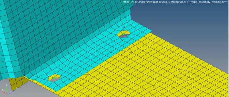
- Rear_truss_2 & Left_Rail_2:- Bolt Connector :- Hide all components except Rear_truss_2 & Left_Rail_2 and deploy bolt connection by following steps –
- Select bolt option in connector type
- Select nodes by path
- Select components to be connected
- Select type as Bolt (general)
- Select create hole, if none option
- Click on create tab it will generate Bolt connection.

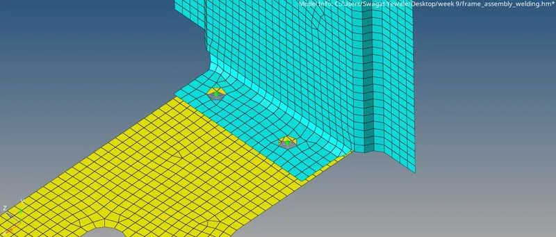
- Right_Rail_1 & Right_Rail_2:- Spot-weld with Rigid Elements :- Hide all components except Right_Rail_1 & Right_Rail_2 and deploy Spot-weld with Rigid Elements connection by following steps –
- Select spot weld option in connector type
- Select nodes by path
- Select components to be connected
- Select type as rigid element
- Select number layers as 2 or auto and select tolerance as 10
- Click on create tab it will generate Spot-weld with Rigid Elements connection.

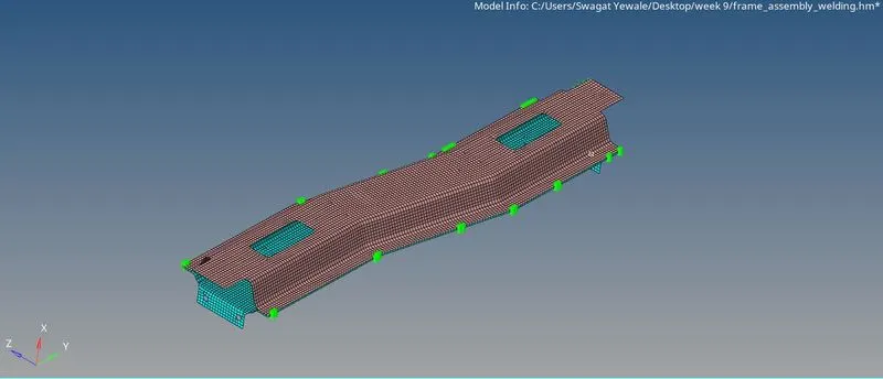
- Left_Rail_1 & Left_Rail_2:- Spot-weld with Spring Elements:- Hide all components except . Left_Rail_1 & Left_Rail_2and deploy Spot-weld with Spring Elements connection by following steps –
- Select spot weld option in connector type
- Select nodes by path
- Select components to be connected
- Select type as Spring Elements
- Select number layers as 2 or auto and select tolerance as 10
- Click on create tab it will generate Spot-weld with Spring Elements connection.

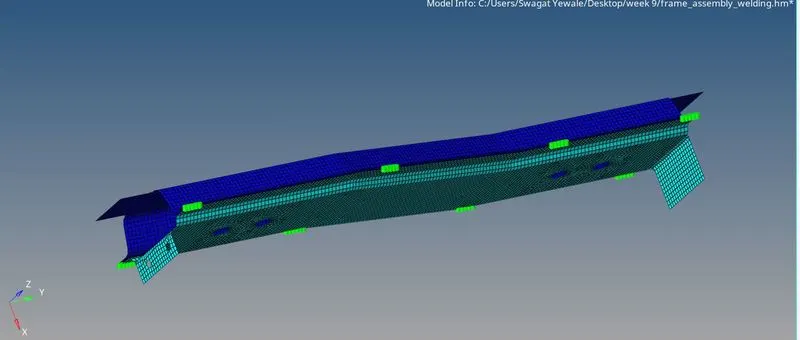
- Rest all the component left Join them with suitable connectors :- For the rest of components connection I had given spot weld connections and for holes RBE2 spider connection, as shown in image below
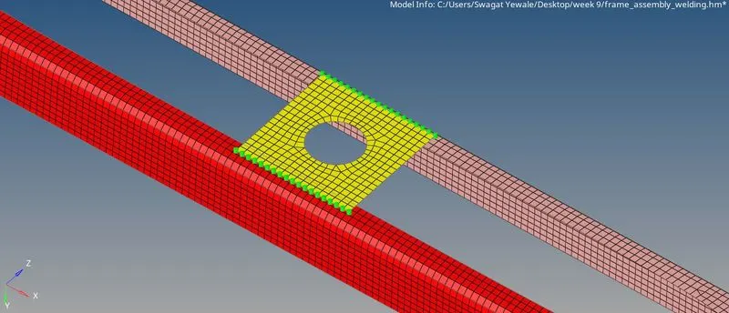
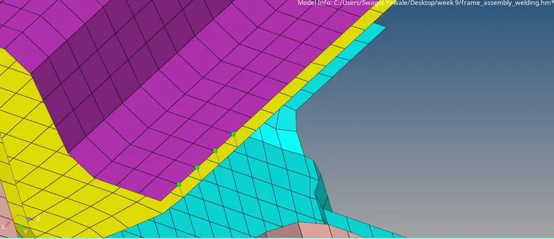
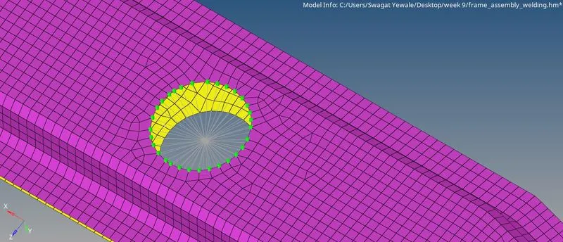
Final View of model :-
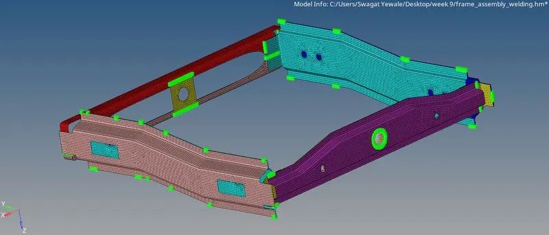
Conclusion :- Thus, the given CAD model is completely meshed and established proper connection in it and model is ready for further post-processing and solving.