Connections Deployment on given 2D meshed Rear door of car
Connections Deployment on given 2D meshed Rear door of car
Aim :- To deploy connection on various parts of car rear door model for NASTRAN deck NVH simulation using ANSA.
Steps :-
- The given model was in .NAS format which is not open directly so we have to open by input>nastran deck
- The given model has available in one single PID so it is difficult to make connections so assign seperate PID for each part.
- Identify the parts where to give rigid bolt or rigid seam weld connection and assign connection.
- Assign the conmass to door handle
- CBUSH connection for door windows.
- Orient CBUSH connection as per vehicle coordinate system.
Brief description of involved steps :-
1) The given rear door model is in .nas format so we have to open thenfile by File>Input>Nastran deck as shown in below image 1.
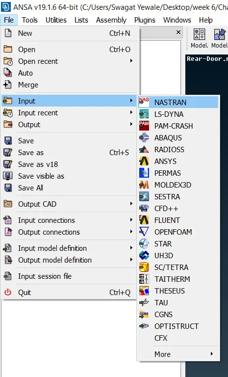
Image 1
2) The given file is available in one single PID as shown in below image 2.1 so we have to seperate each parts and assign seperate PID for each parts as shown in image 2.2 below
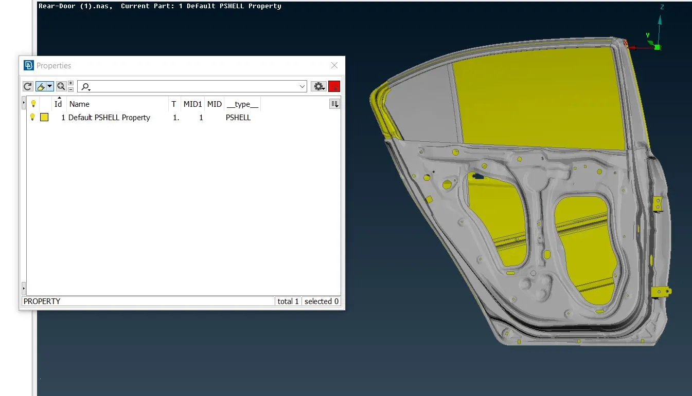
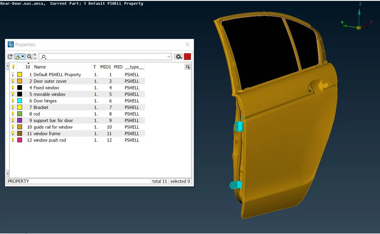
Image 2.1 Image 2.2
3) After assigning PID to each parts,identify the connection between these parts in given model. there is some parts attached with bolt connections and some are spot weld and seam welds, this connection need to be realize for simulation and its results.
3.1] A rear car door is typically hinged as shown in image 3.1 so first need to do connection on both hinges.
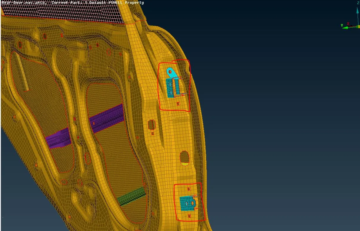
Image 3.1
3.2] Here,for establishing connection of bolts i create 3D points by TOPO>Points>On COG option.and convert these points into bolt by convert option as shown in below image 3.3 For realizing this bolt during NVH simulation i used connection selection assistent and select this bolts after midle click connection manager window is open there select P1 and P2 as a two surfaces which is to be bolted and select FE type as bolt,type search distance 10,select zones as in/out and body type RBE2 and click on realize option then bolt connection is done as shown in below images.Similarly do connection for others bolted areas.
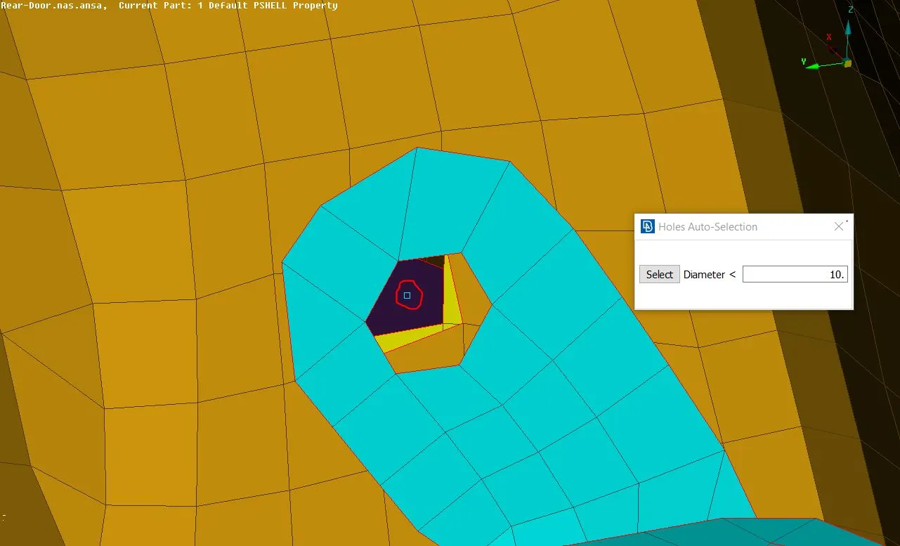
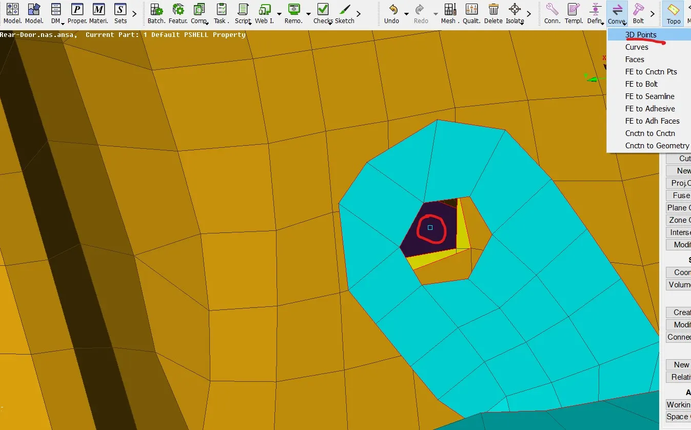
Image 3.2 Creating Point on COG
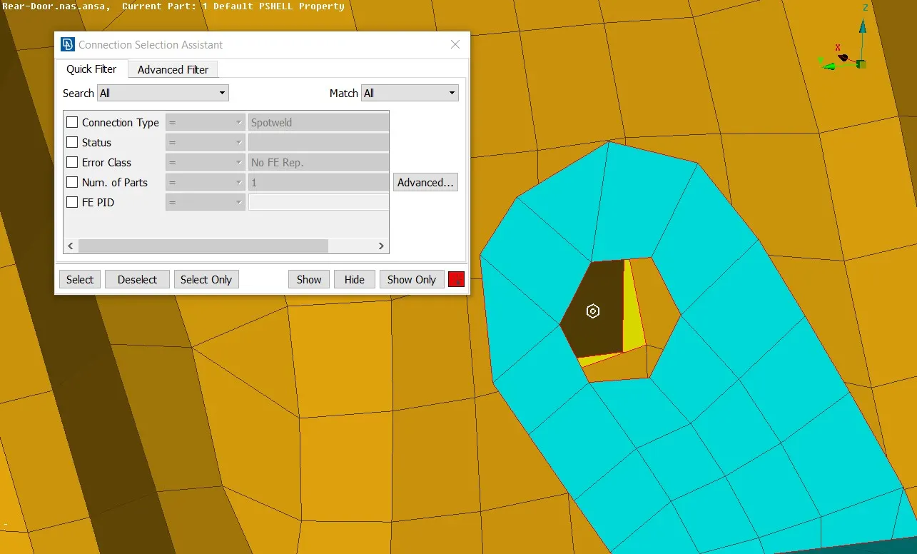
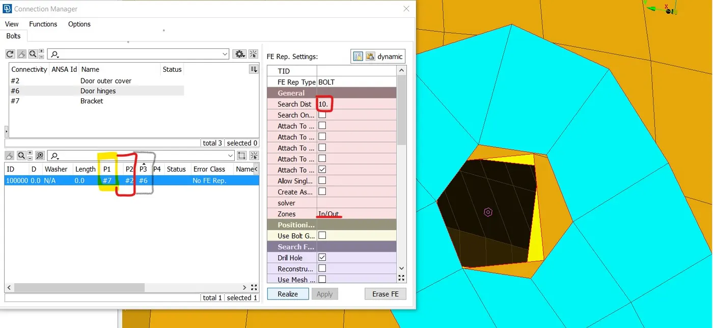
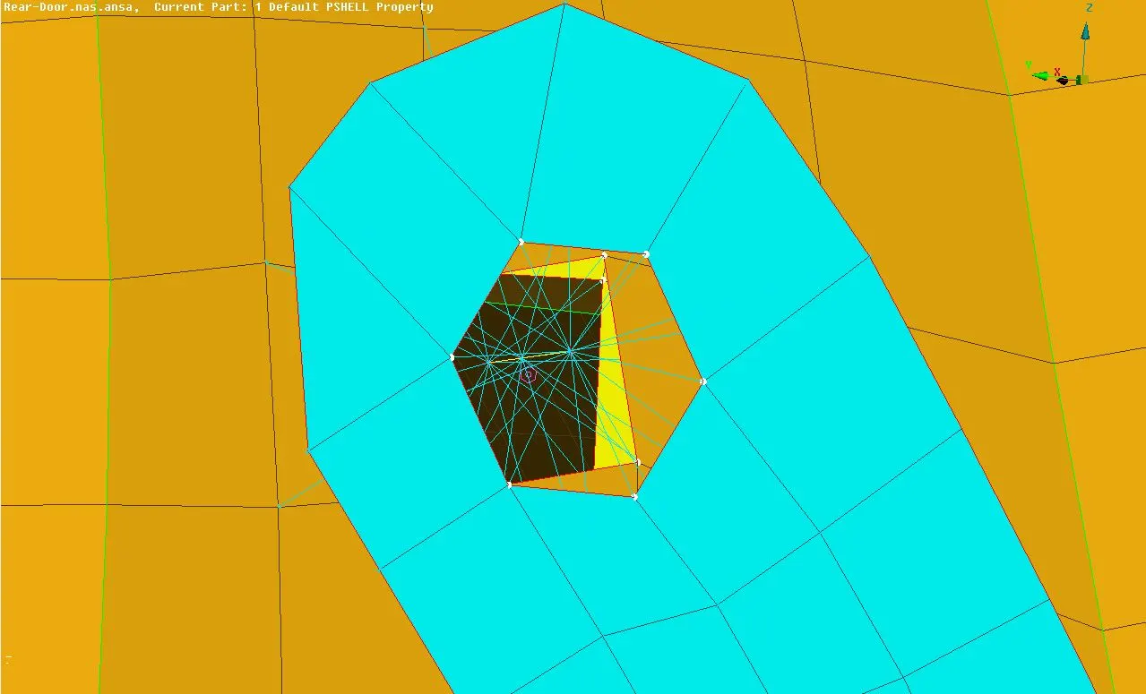
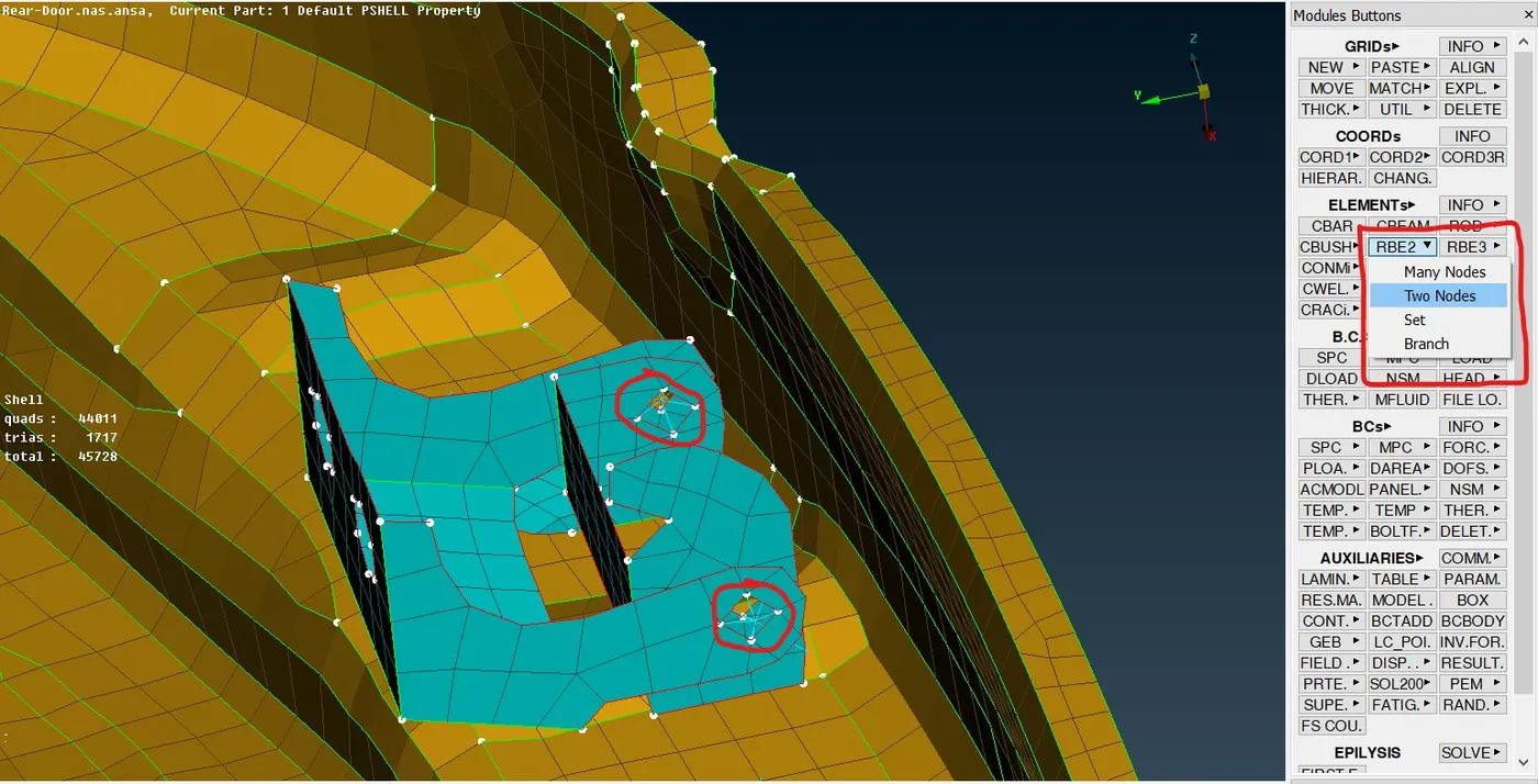
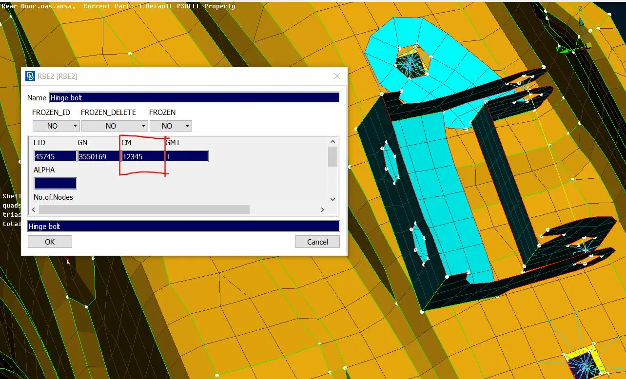
3.3] For creating bolt connection for hinges,first make cluster of both sides holes and then with help of RBE2>Two nodes join the both clusters master node and bolt stem is formed for this stem restrict one degree of freedom as door is rotated along Z-axis for close and open operation as shown in below images.
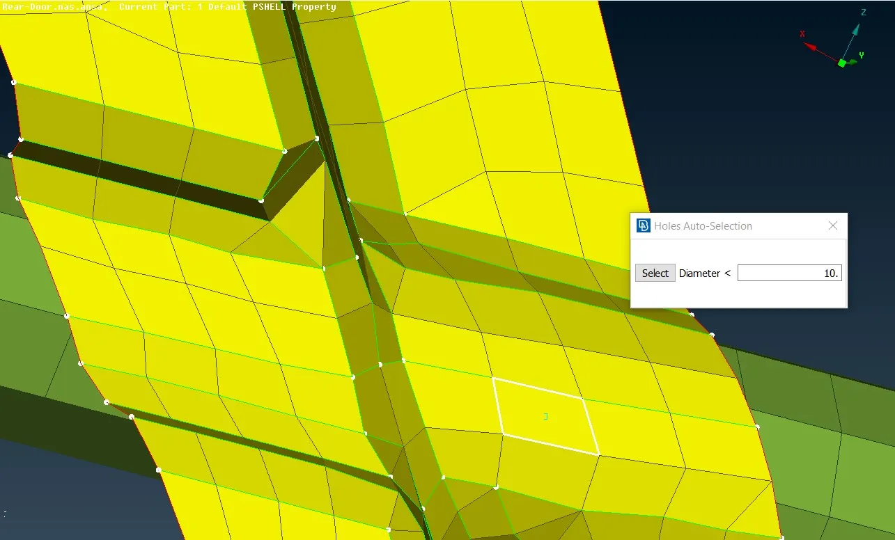
3.4] For some instances need to deploy spot welt for spot weld first create 3D point by Topo>Points>On COG option and then convert this point to spotweld by convert option after converting open connection selection assitence window and select weldspot after that on midle click connection manager window opens in connection manager window select p1 and p2,select FE type as a RBE3-hexa-RBE3,type search distance as a 10,select Psolid id of weld spot(If it is not creat it by right click>New option),type RBE3 pinflange as 123456 and select on apply and realize option after that solid connection between two points is established as shown in below images
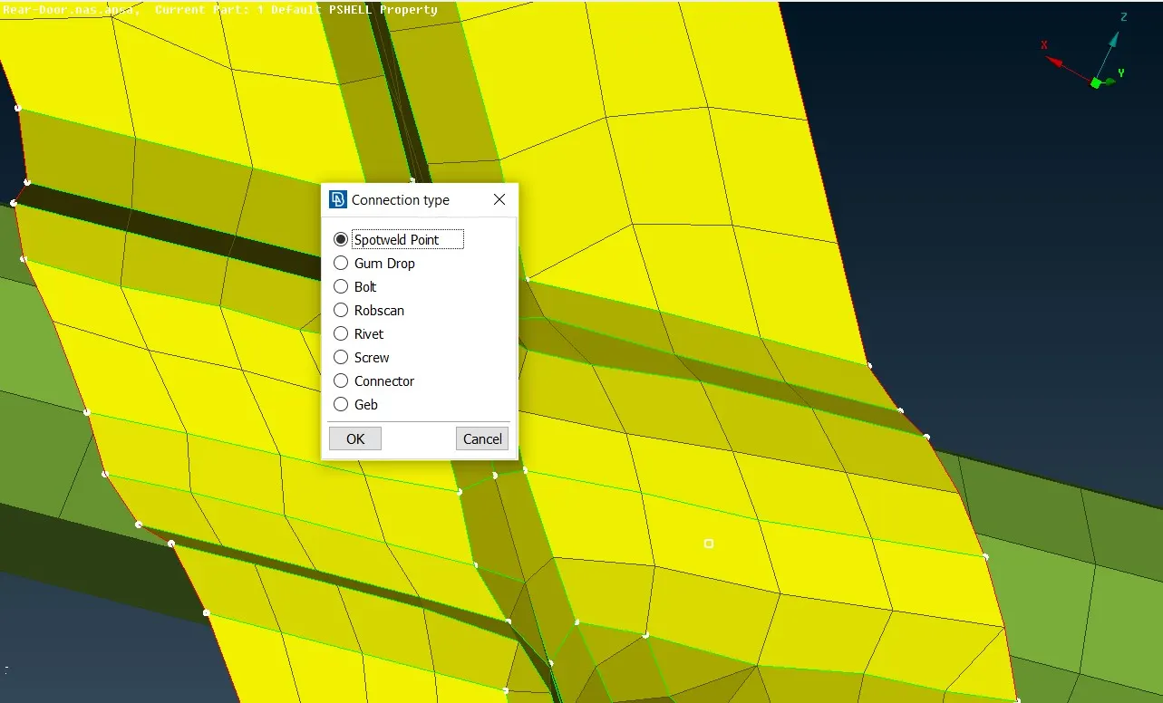
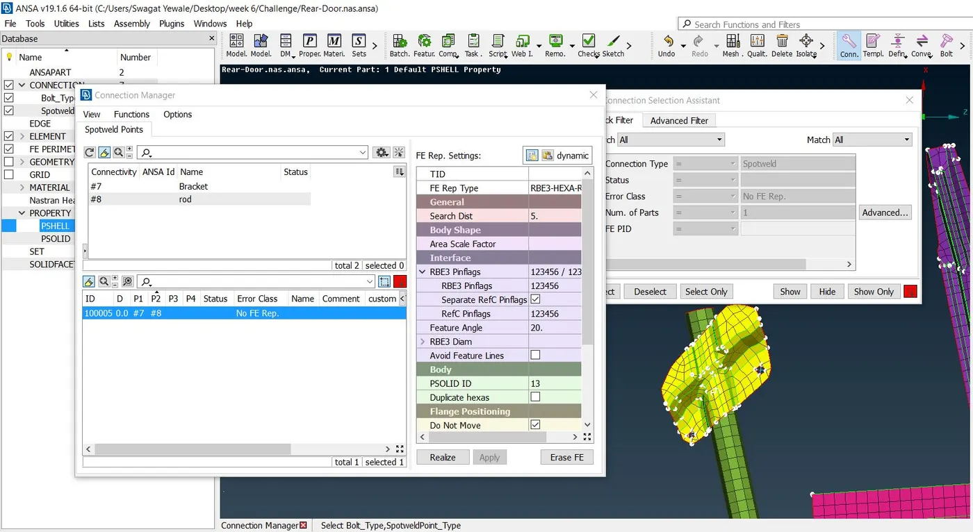
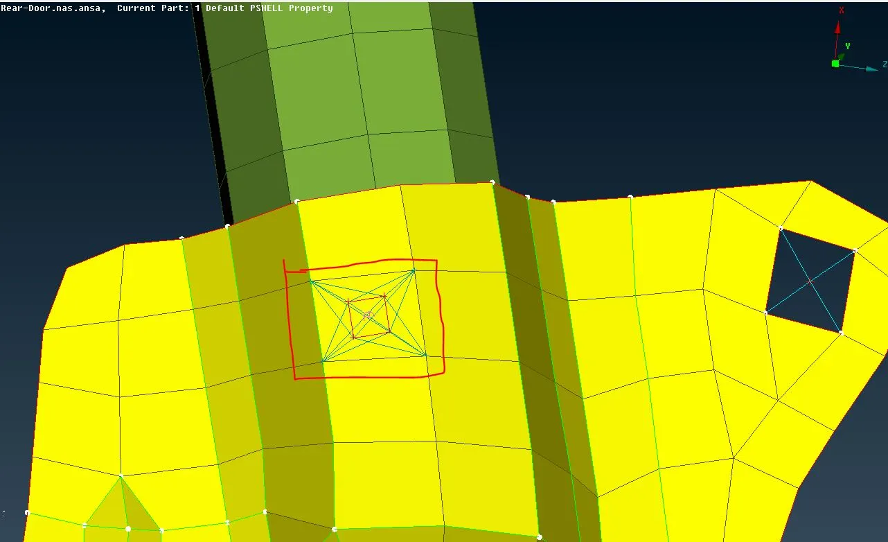
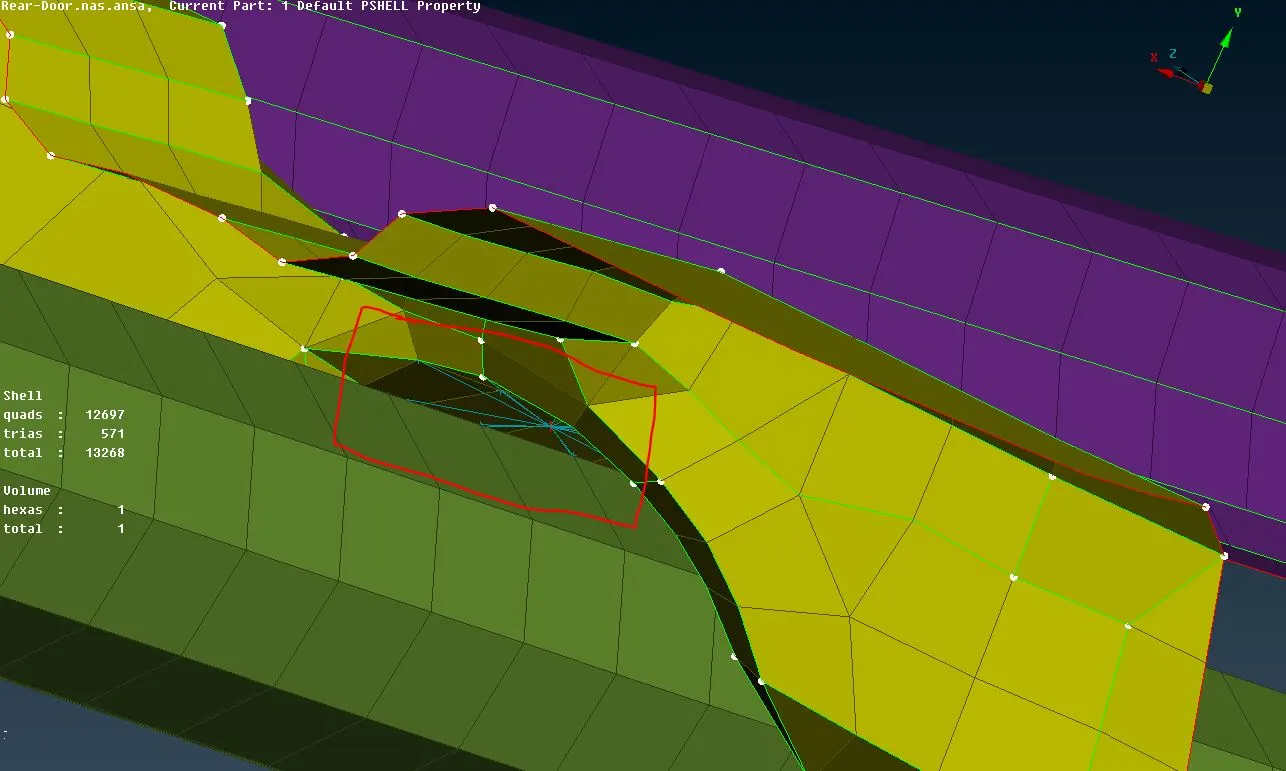
3.5] For some location spot weld is not applicable, while realizing spot weld connection it shows "Connection were too close to bounds" error in info tab for that situation we can realize the rigid suhpport by RBE3 nodes option.In RBE3 connection centre node is slave node and other node is master while in RBE2 connection centre node is master node and others node is slave nodes,this is the difference between RB3 and RB2 connections.
4) Door handle connection
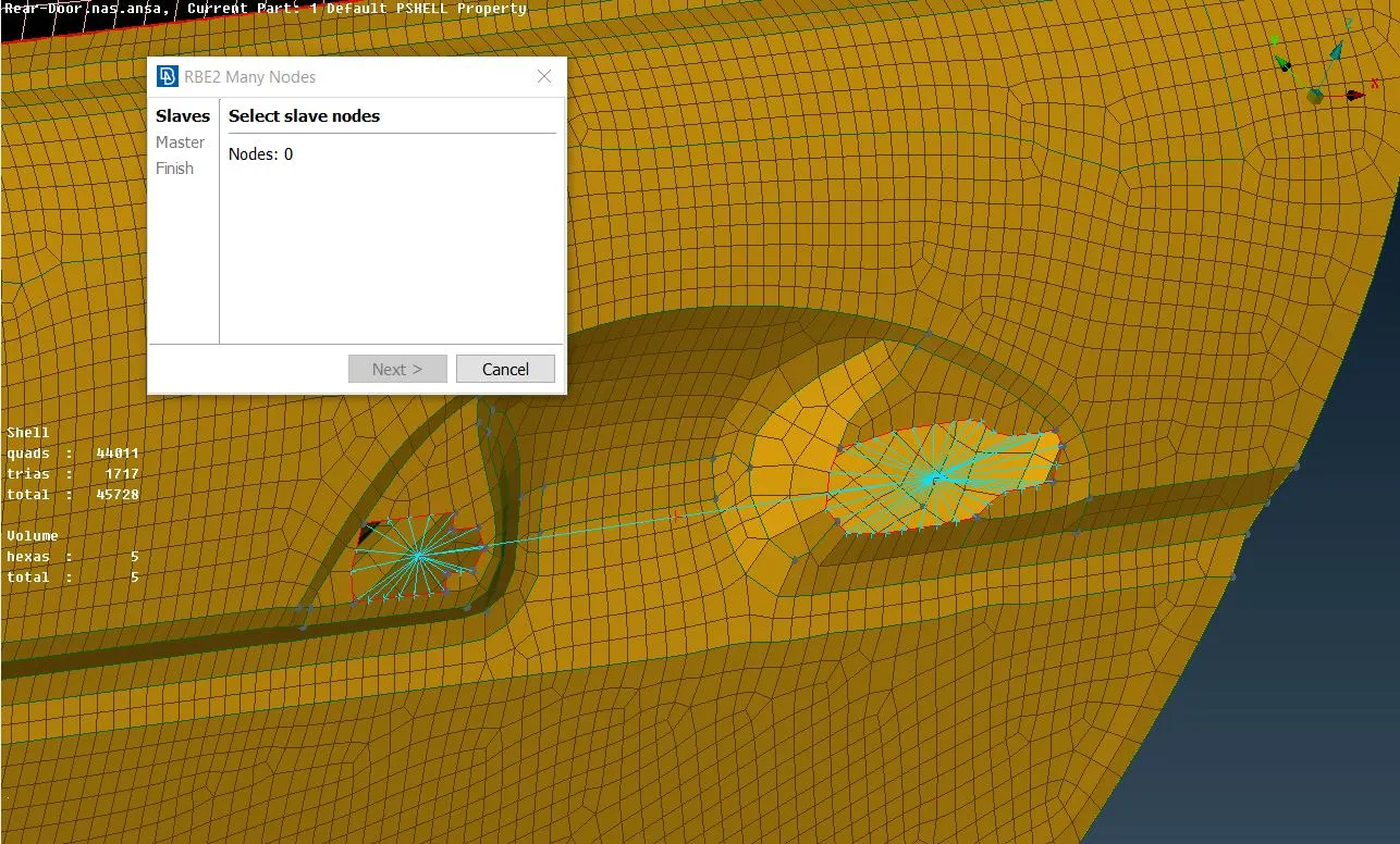
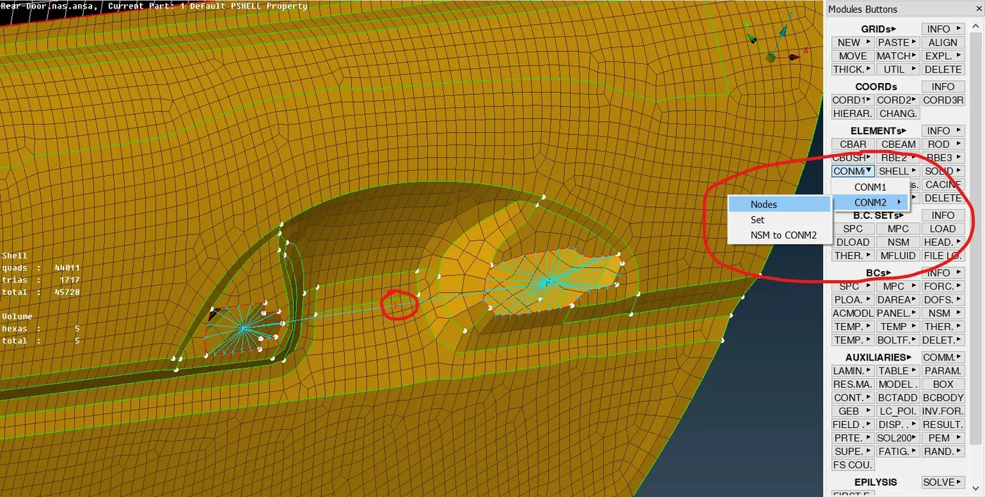
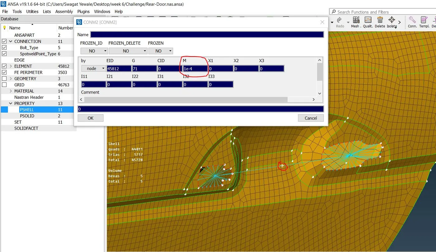
For NASTRAN NVH simulation door handle is not converted into FE only mass of door handle is taking in consideration.here mass of door handle is not given so consider it has 100gm. For assigning mass to door handle in nastran deck conmass is option available. For using this option first esablish the cluster connection between spots of door handle as a many nodes.After that use NAS>Elements>ConMi>ConMi2>Nodes option for assigning mass of door handle to on one master node.In ANSA all mass is in tonnes so convert gm to tonnes and assign mass.
5) Connection of window
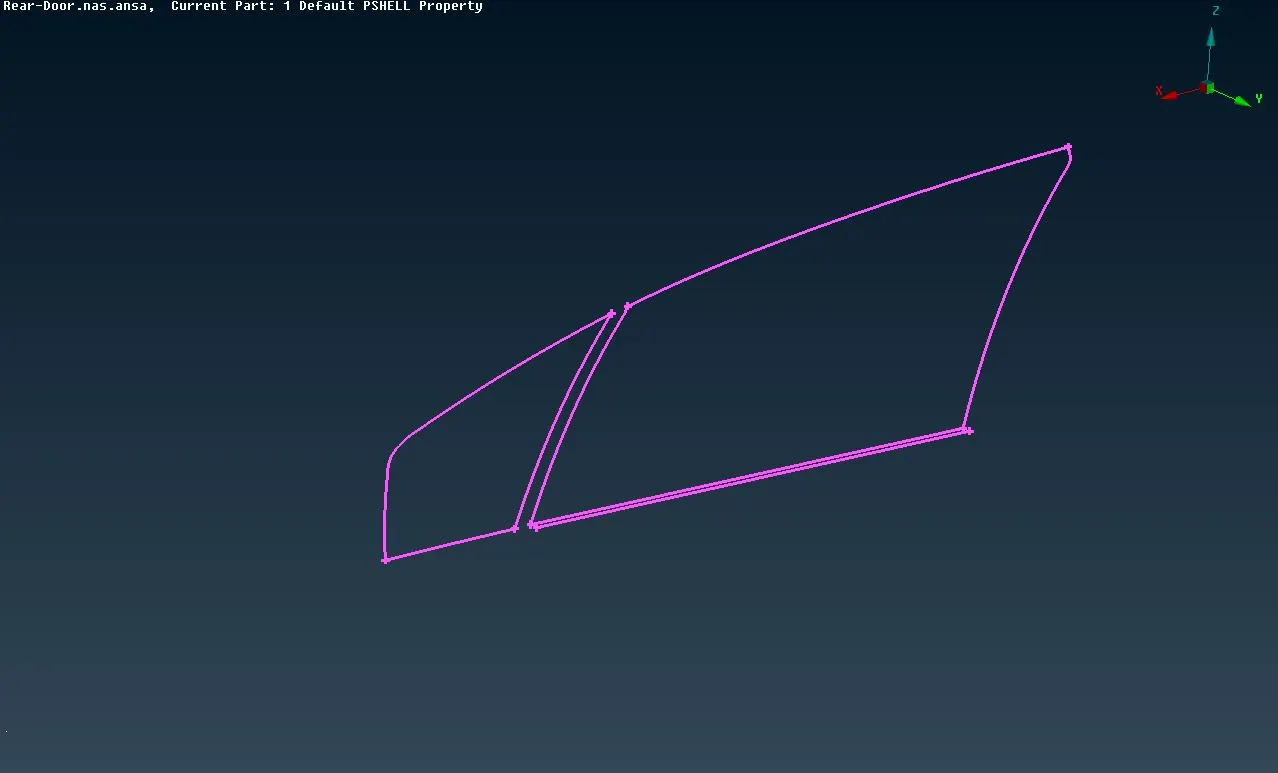
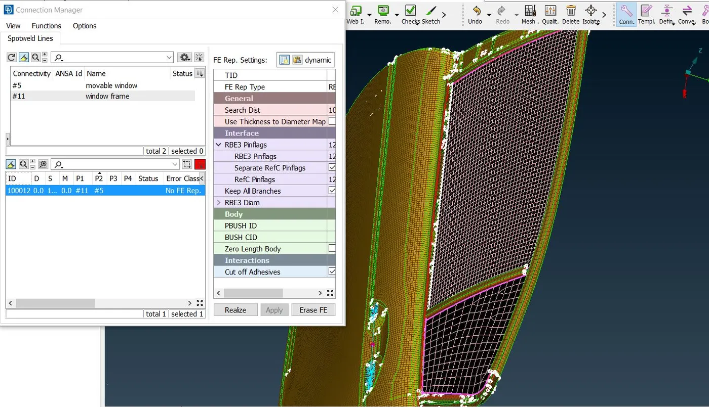
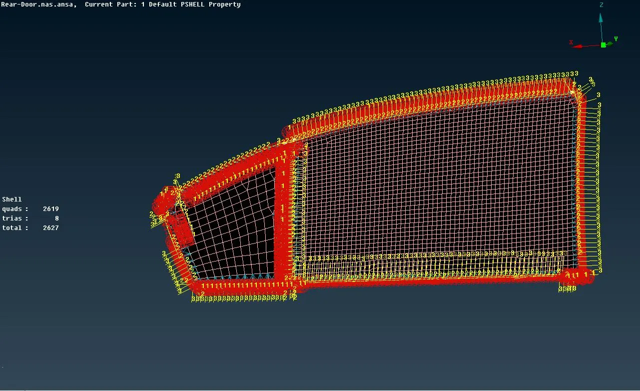
For connection of window to door first need to create curve by Mesh>Perimeters>Feat2curve option on outer perimeter of window and from bottom side add new curve with distance of 10mm by transfer>coppy option. After that convert all curves to spot line one by one .After that open connection selection assistant window and select any spotline and after clicking midle button connection manager open in that select P1,P2 as a part of window and mounting,select FE type as RBE2-CBUSH-RBE2,select search distance 50,click on keep all hinges,select CBUSH ID and click on apply and realize CBush connection is established between window and door.Simillarly do for others sides of the window.
6) Orient CBUSH Connection of window with vehicle coordinate system
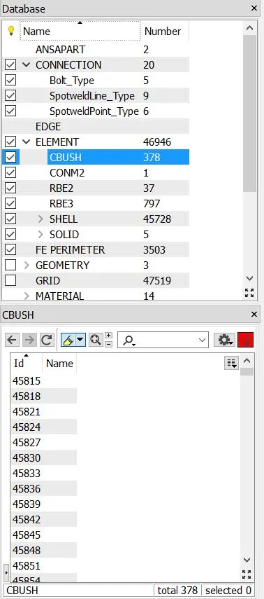
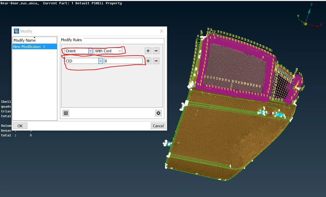
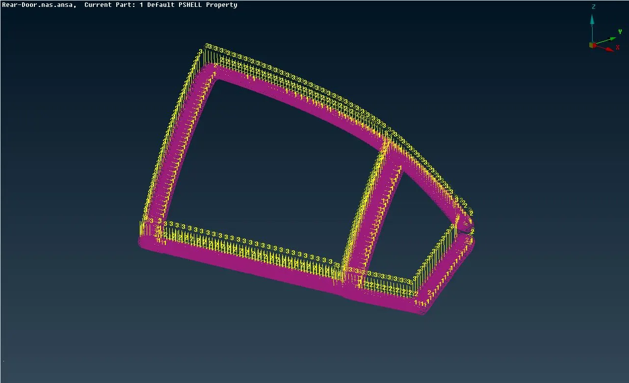
After establishing CBUSH connection of window with door the CBUSH vector is oriented with Vector so that direction of CBUSH connection may varies so we have to orienet the CBUSH with Vehicle coordinate system for that open elements option in database in that select all CBUSH ID and click rightclick and select modify option in that select orient and orient with cord and select CID as a 0 and click Ok so all CBUSH is oriented as a vehicle coordinate as shown in below image.
Learning Outcomes :-
- Types of connection and identification of it
- Establishing of connections for NVH simulation
- Understand different types mechanism used in car
- assigning body mass to perticular part
Conclusion :-
Thus, the connection has been deployed over car rear door model for NVH simulation.