2D Mesh over plastic bottle screw cap with given quality criteria
2D Mesh over plastic bottle screw cap with given quality criteria
Aim :- To perform geometry cleanup,extracting mid surface and 2D meshing over plastic bottle cap with given quality criteria.
Objective :- To improvise the method of extracting mid surface for a casting components and meshing over it without any quality issue.
Procedure :-
- Import CAD model to ANSA.
- Perform TOPO and geometry check on CAD model.
- Clean all geometric errors and measure thickness of various parts to extract mid surface.
- Extract mid-surface of CAD model by using various method.
- Assign the given mesh criteria and quality criteria.
- Meshing to the extracted mid surface according to given quality criteria.
- Resolve quality issues occuring during meshing.
Steps :-
1. Import CAD model to ANSA
The given model is plastic bottle screw cap component which means it varies thickness. A bottle cap typically decorated with logo of brand of braverage company.The given component has internal threads and ribs for effective seal,to be easily opened by consumers and often to be reclosable. The plastic bottle caps generally manufactured by injection molding method.The plastic material are put into machine that heat and mixes them,then pushed into a mould cavity.In the mold cavity it will cool off and harden to that mold shape.The bottle caps are shaped with a machine that creates the dip along the edges.
2.Perform Topo and geometry clean up on CAD model
While importing CAD model into ANSA various collapsed faces and gaps occued as shown in below figure which is not acceptable in meshing therefor after importing CAD file always perform topo oparation to entire model. After performing TOPO all collapsed faces and gaps are eliminated automatically by ANSA software.below images are before performing topo option and after performing topo option.
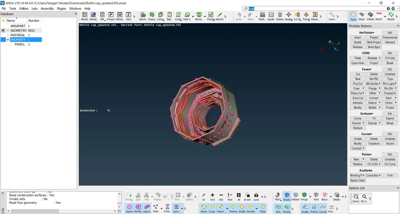
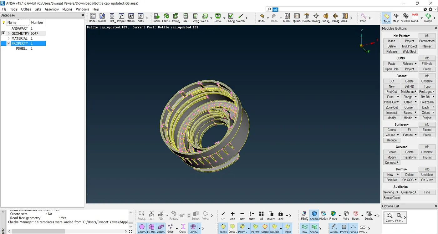
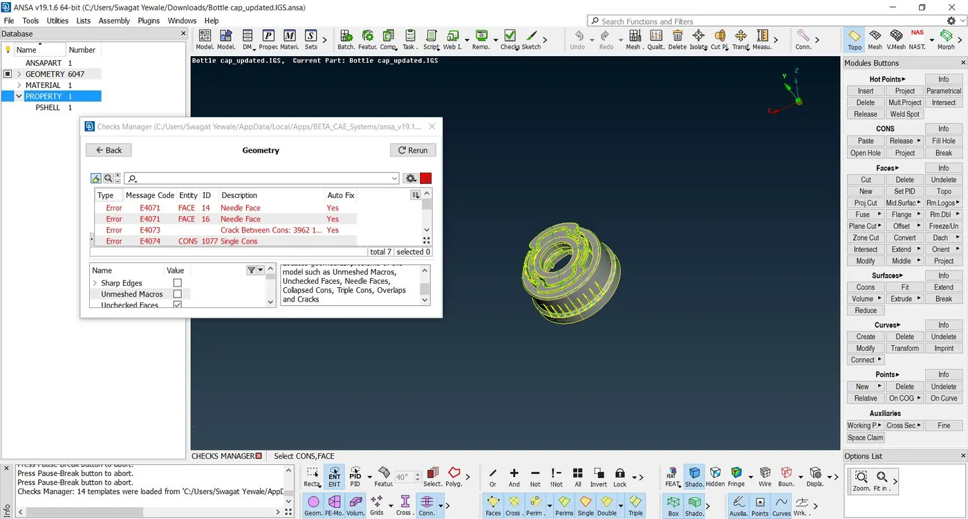
Geometry errors cleanup are done by ANSA automatically by fix option but it is always better to resolve errors by manually for better understanding of CAD model geometry and knowledge. In this challenge i resolve all errors by manually.ANSA can identify and isolate geometric errors in the model that requires users attension.click on the 'checks' button located in the 'tools' toolbar on the top of the screen and select geometry. The check manager window opens.her you can select the type of errors that may exist in modelto be investigate by activating corresponding flag in the lower part of window.Keep the default option and click on excute.
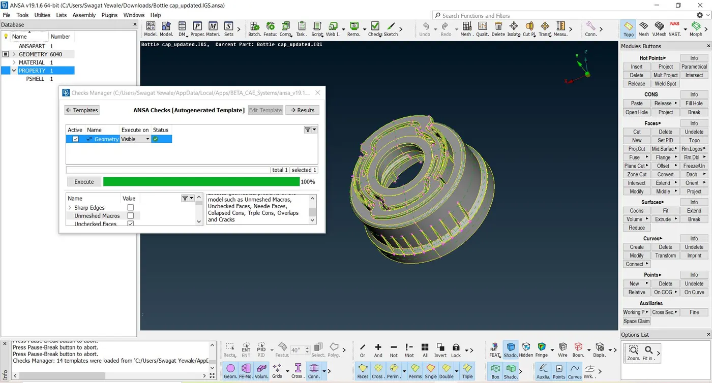
In this given model ANSA identifies total 27 errors in the geometry of model you can highlighted any of problemetic areas by left clicking on it or isolating it by right click and show only option. depending upon the type of the problem ANSA also offers the option to automatically fix it. Before and after geometry check images are shown below.
3. Clean all geometric errors and measure the thickness of model of various parts.
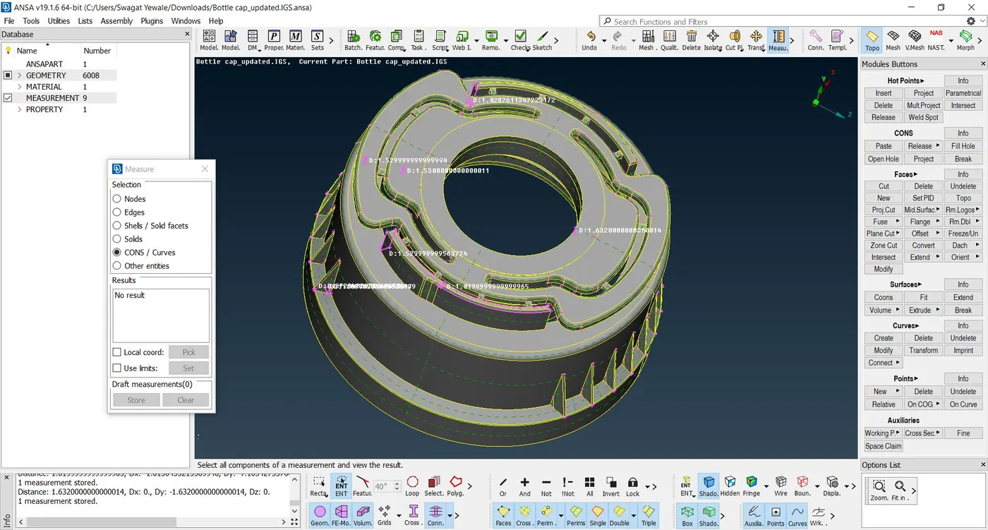
After clearing all geometric errors measure the thickness of various parts.Since it is plastic component there are varying thickness to various parts,also thre are various ribs,internal threading and teeths are present in the model. the thckness of components can be measured by Utility => Measure option.there we can measure various distances such as beetwin nodes,edges,faces,cons and curve. similarly we can measure thickness for various parts.
4. Extraction of mid-surface by various methods.
In ANSA mid surface can be generated by automatically (Faces => mid-surface) and manually. Sometimes in auto mid surfaces method the genetaed mid surface cannot be correct due to complexity of geometry of model and also in this method parent surface is deleted by automatically without our permission.while in manual mid method we can keep parent surface or delet.Manual method is time consuming but mid is generated is correct one.
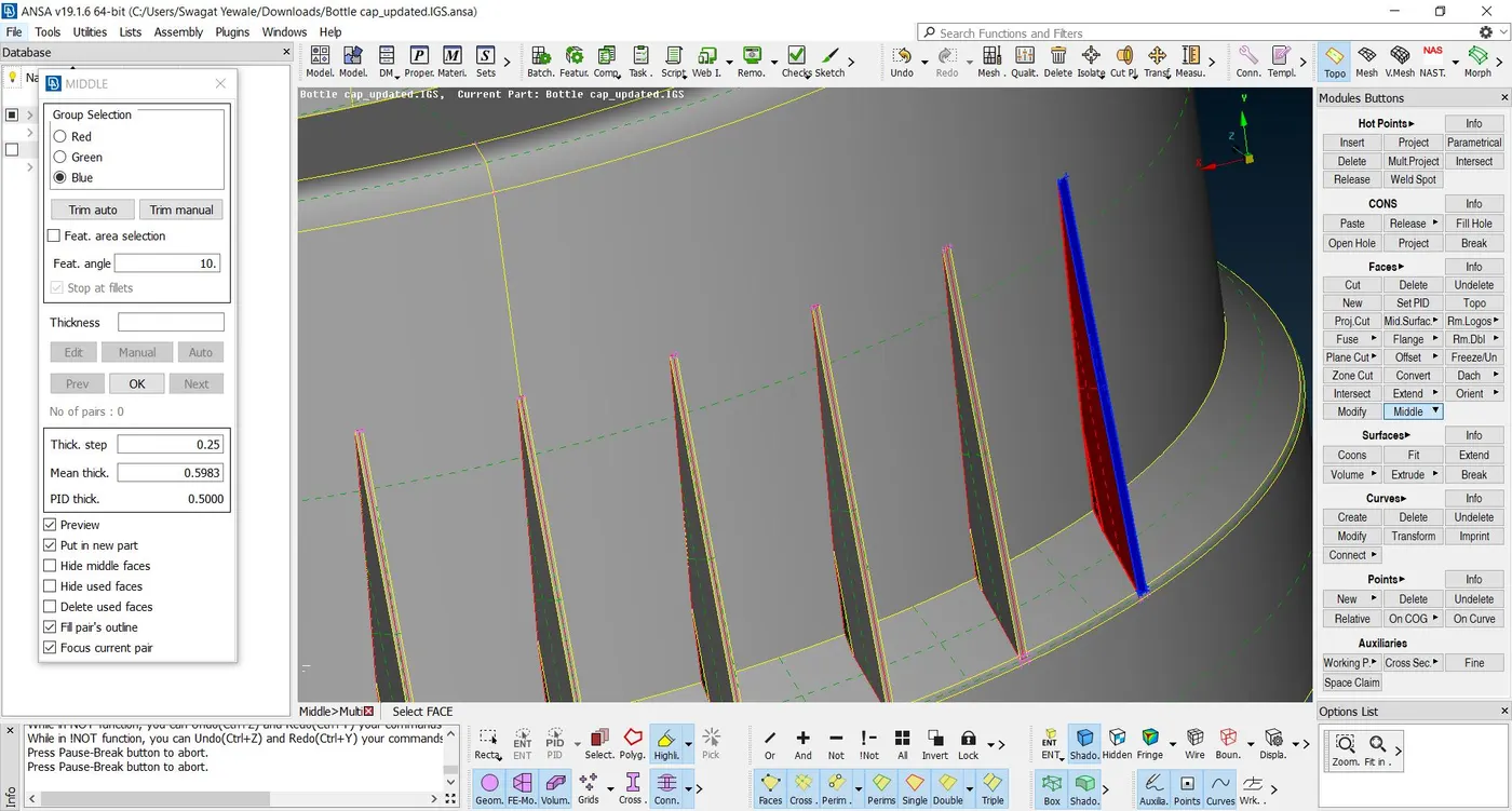
In this challenge i use manual method for extracting mid for meshing,it is time consuming but generated mid is correct one. In some parts for extracting mid surface i used Faces => midle=>multi option as shown in below image
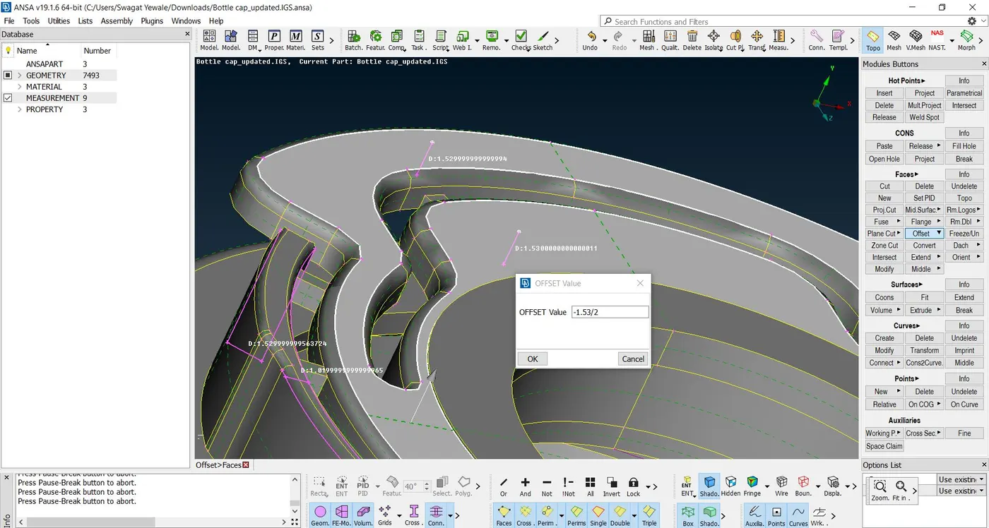
Sometimes i use Faces=>offset method by calculating thickness by projecting weld spot on opposite faces. By calculating distance between two nodes i make offset surface at mid of that distance as shown in picture below.similarly i take mid of other uneven thickness parts.
Some parts having uneven thickness i used Curve => Midle option for creating reference curve for generating mid surface (Faces=>New) as shown in below image.
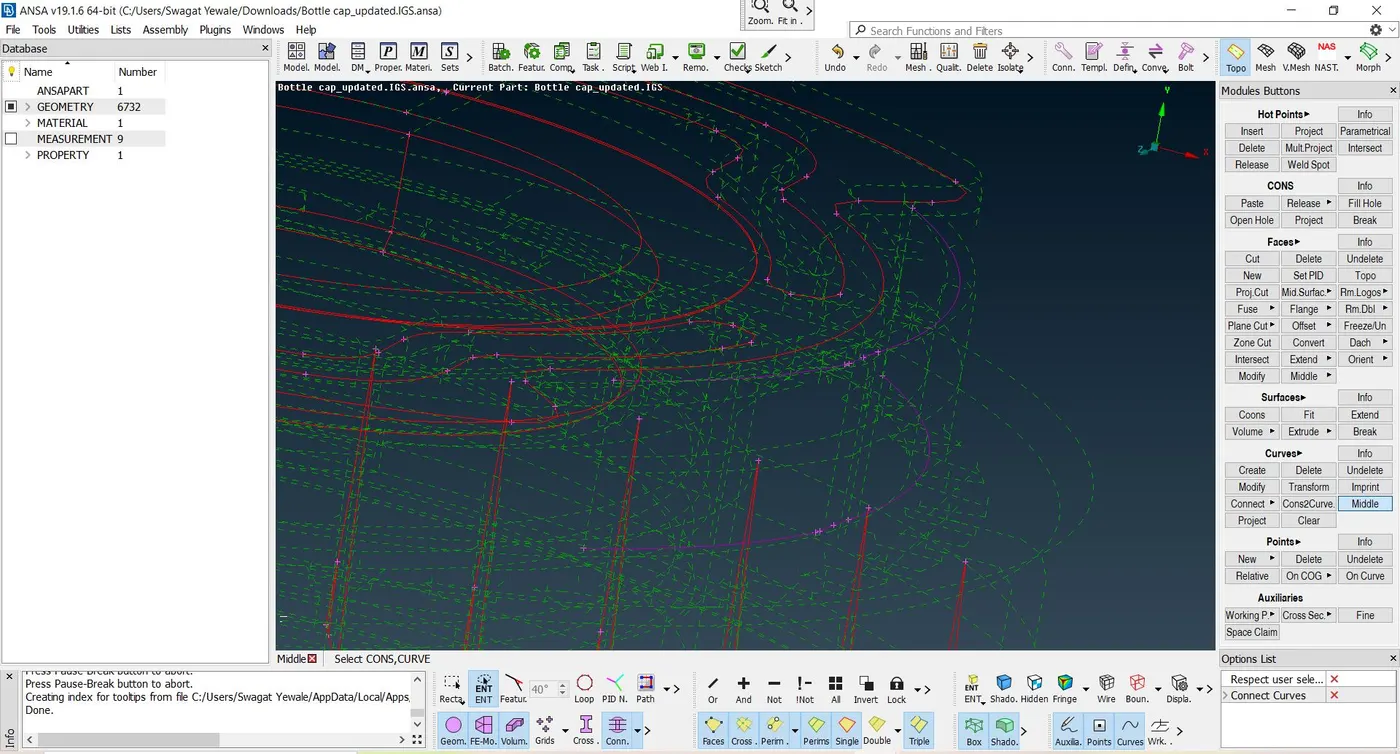
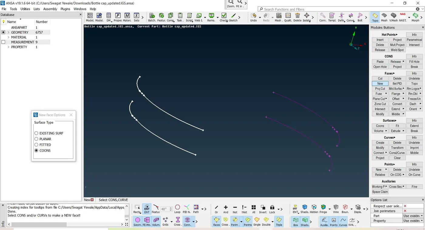
For threads, it is impossible to taking mid of trapazoidal threads so i consider trapazoidal threads as a rectangular and taking mid of threads by Curve=>midle option as shown in below image and created new surface between these two curves.
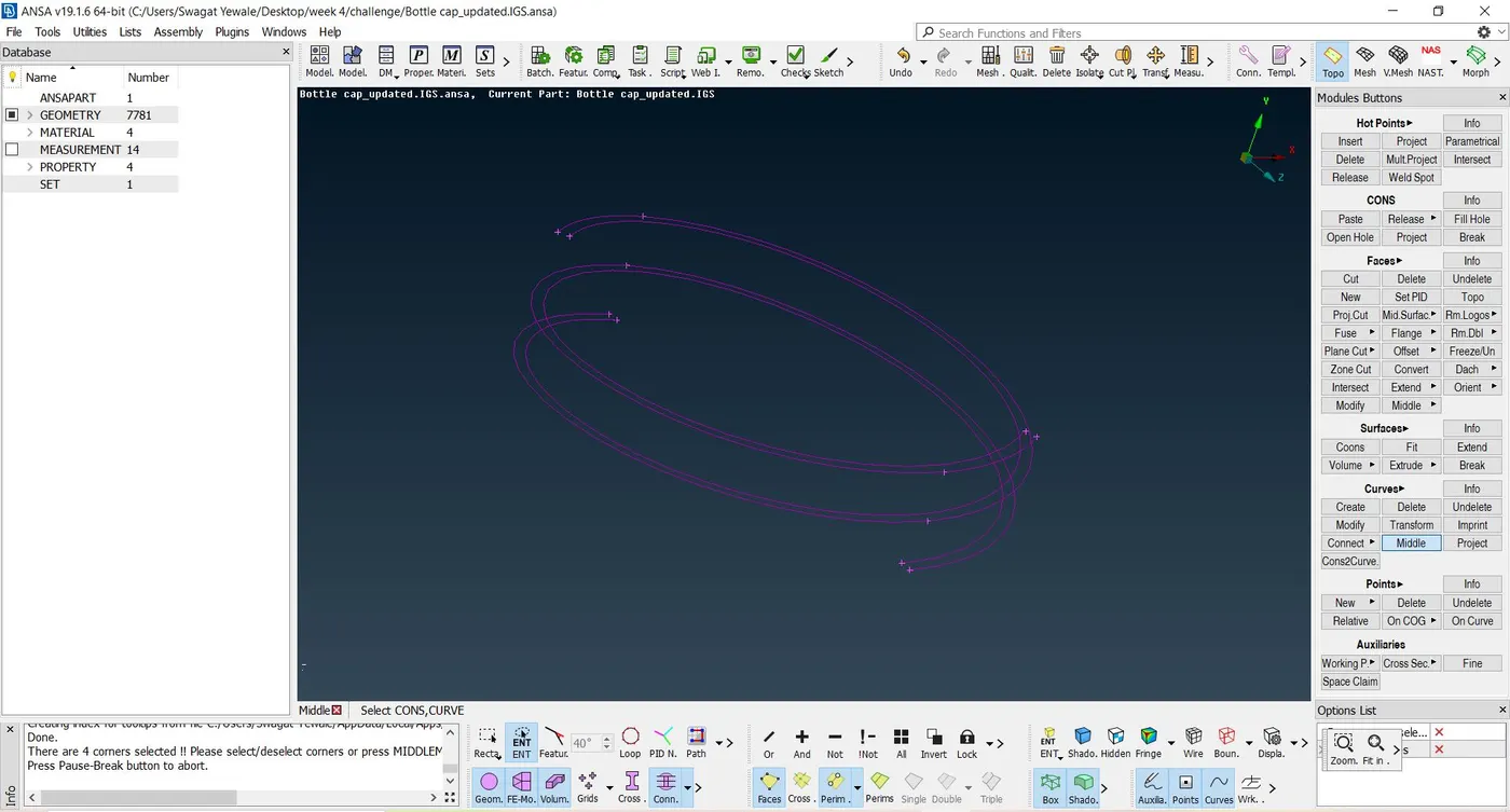
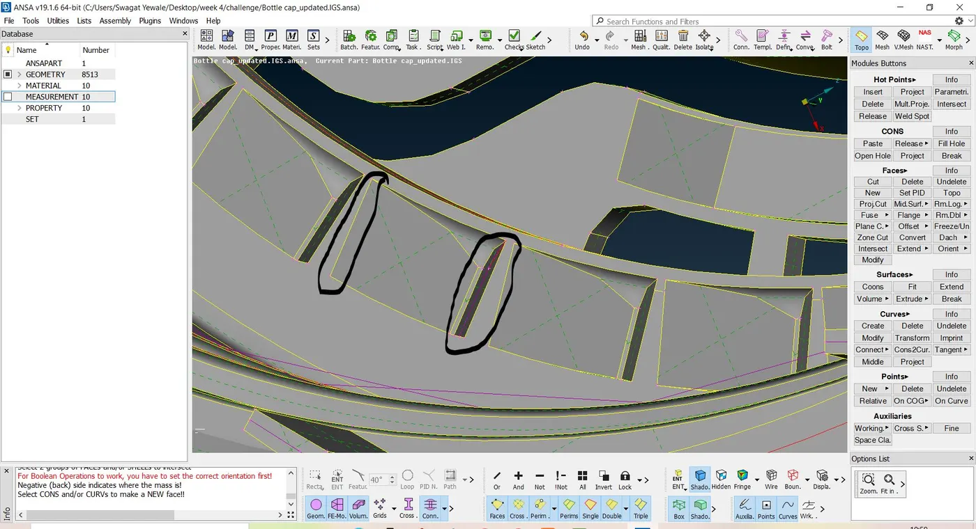
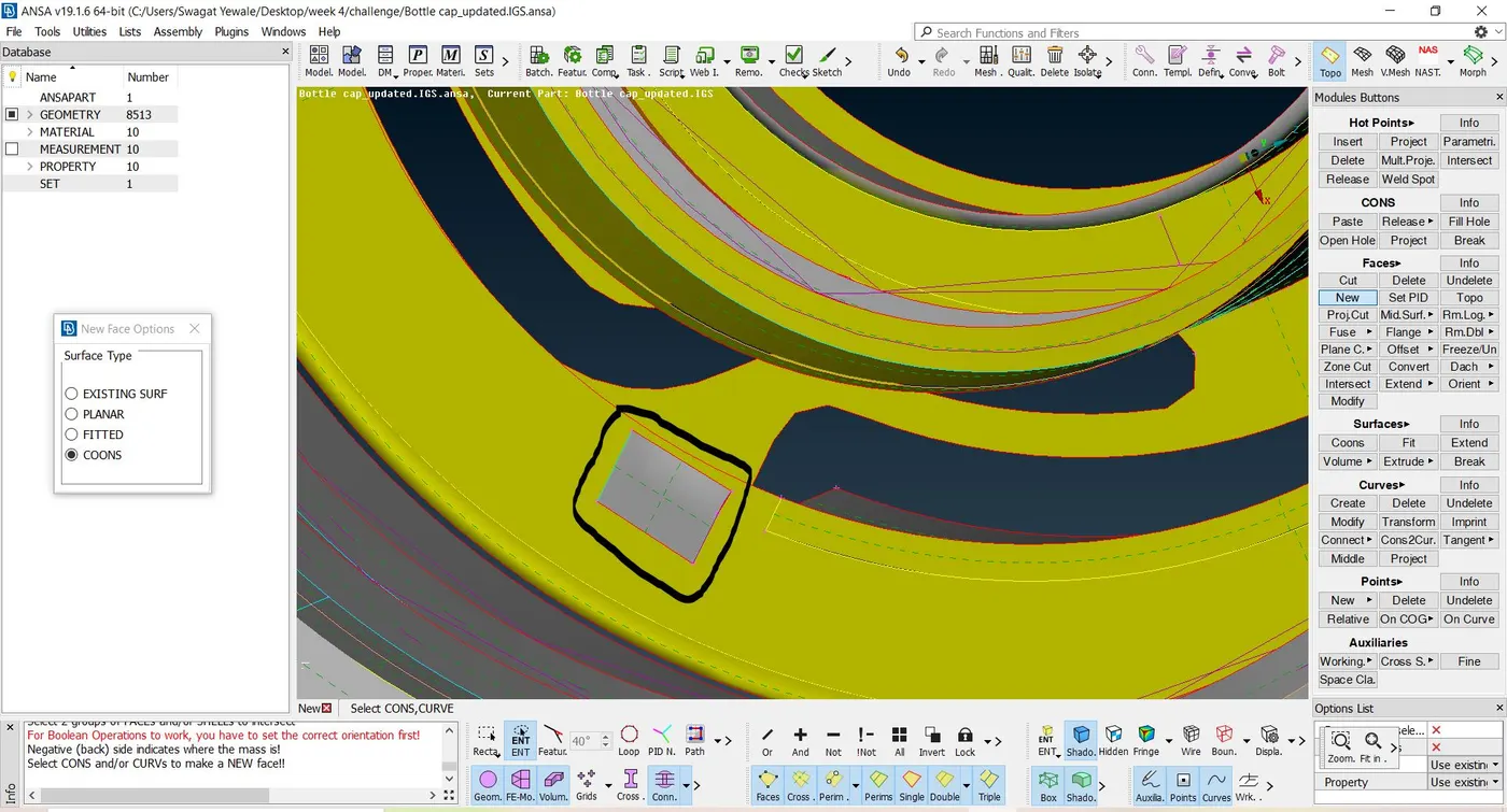
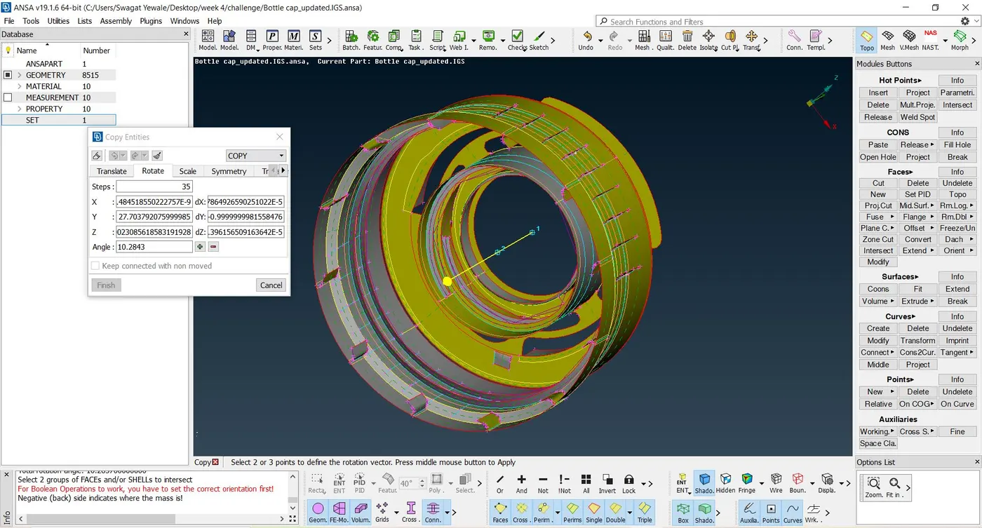
For taking mid of teeths i select one teeth and taking mid of that teeth by selecting curve midle option on two front side edges of teeth and projecting base coon on mid-srface and created new surface in between them. It is time consuming if the mid surface is extracted one by one so here i used the Rotate command under transform option in utility section in order to save time.(Here,The idea is take mid of any tooth and duplicate it to required numbers.In order to for using rotate command first i created two centre points by Poiints=>On CoG option at two different height.
After creating two CoG points, from transform=>rotate option i type number of steps is 35 and in X1 column i select my first CoG and and in second column i select another CoG and after pressing and in angle tab i type 10.2843 Because in model there are total 36 teeths so 360/35=10.2843 (35 is because of one is reference teeth) So at 10.2843 degree all teeths are copied(Dupicated).Refer given images below.after accepting we can see teeths are formed,then i extended base edge of teeth to mid surface of base
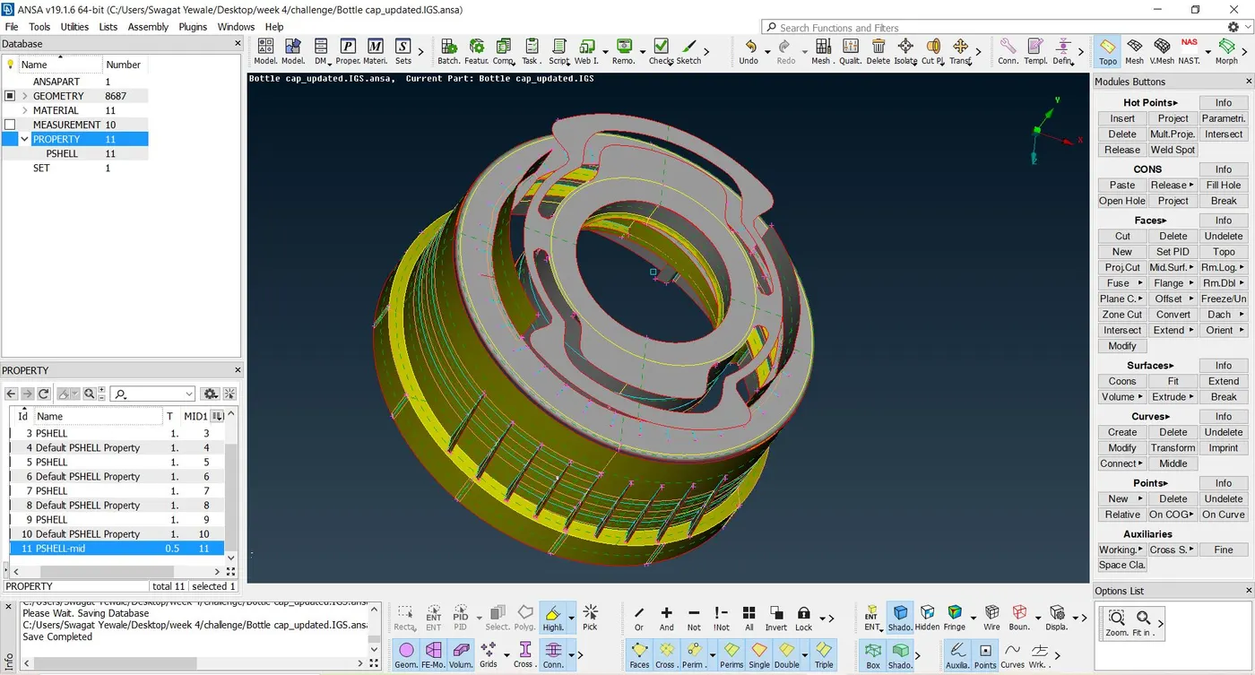
After that i assign the new PID for total mid surface by Faces=>Set PID option,and assign the thickness to mid surface.
5.Assigning the given Mesh and Quality parameters.
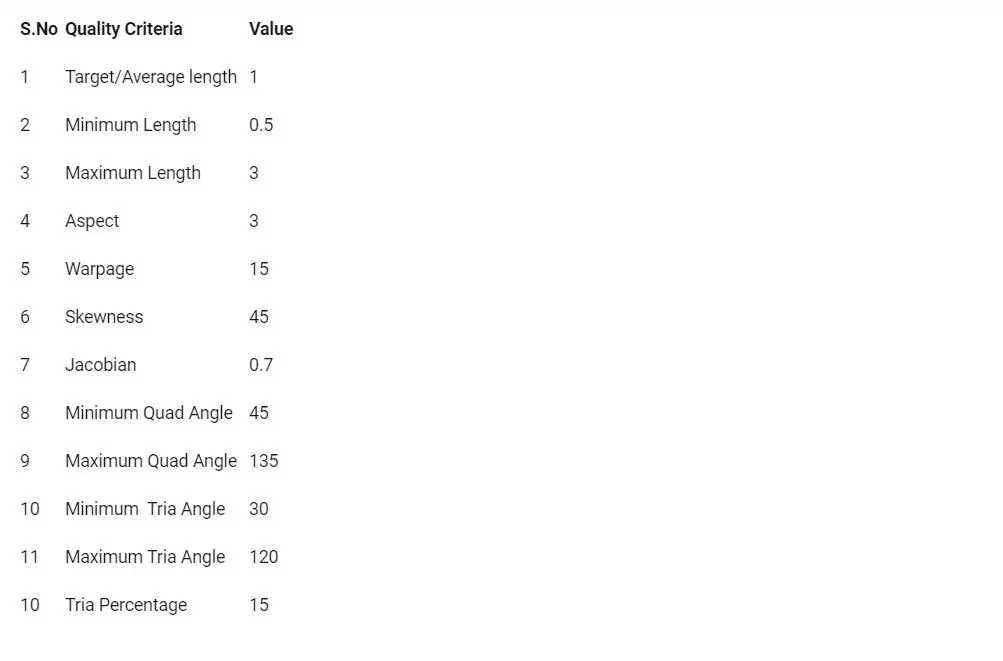
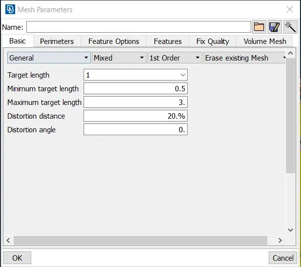
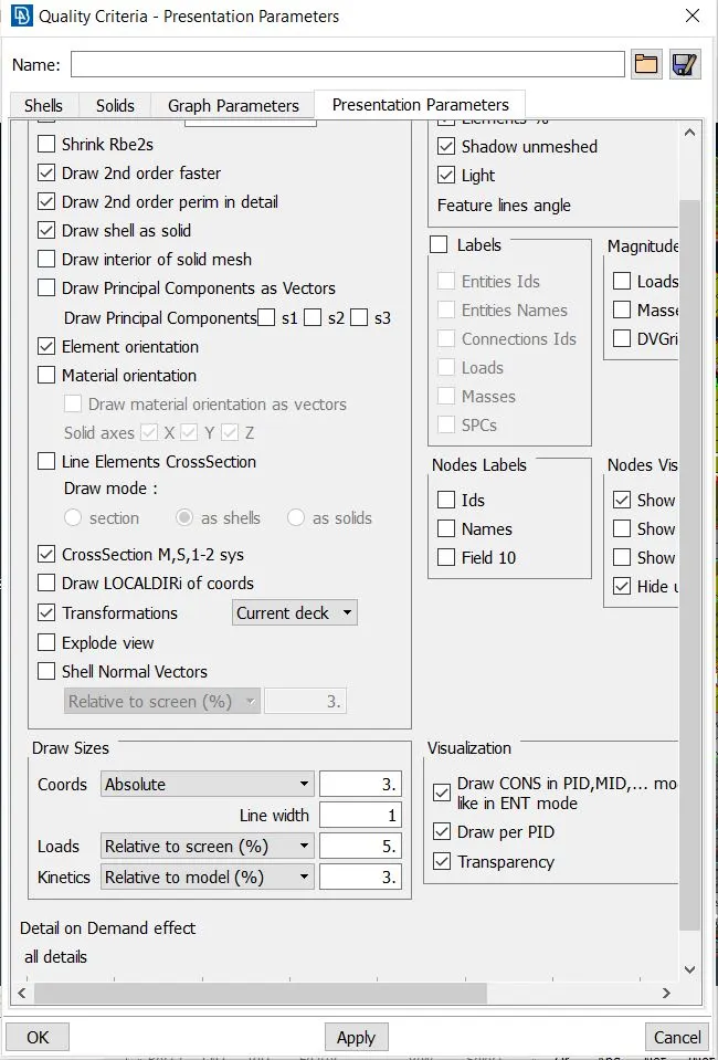
After thickness given to mid surface, need to assign quality parameters and mesh parameters. I assign given parameters as shown in below images.
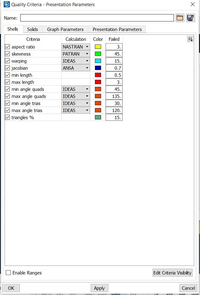
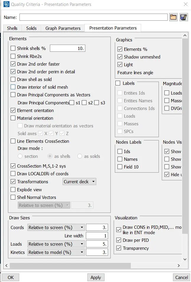
6.Meshing as per mesh parameters and quality parameters.
Meshing is done under TOPO module for meshing i used Mesh=>Best option here i select one by one part of component and meshing is done during meshing various issues occurs which can be seen in hidden mode,to resolve these issues i used Num+/-,reconstruction,smooth,split,swap,join,etc options. Oppostite trias,tria at paremeters,wavy mesh flow pattern is not acceptable in meshing.For better mesh flow pattern i devide part by cut option and after again these cuts are removed by join option.
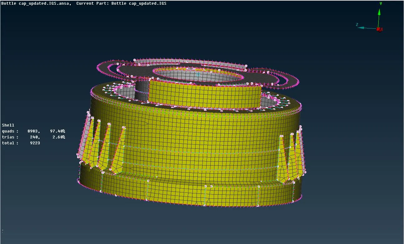
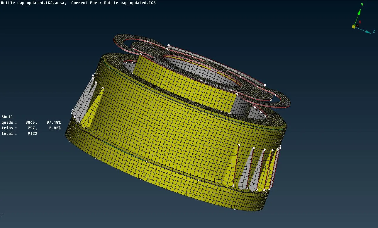
To obtain FE model from parent geometry use Elements=>Release option and disable geometry from visibility window the showing model is our final FE Model which is going further analysis.After obtaining FE model enable the draw shell as solid option the image after enabling this option is given below.
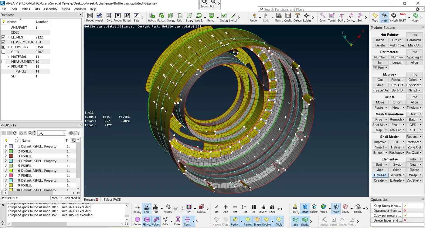
Learning Outcomes :
- In this challenge i understand the how to take the mid of uneven thickness parts of casting materials
- To obtain mid of threads,teeths and ribs of plastic components.
- New rotating command for duplicating same feutures in component.
- To obtain better meshflow over complicated areas.
- To obtain shell as solid model from FE model.
Conclusion :
The given plastic bottle cap component is checked for geometric errors,extracted mid surfaces of component and it is meshed with 97.18 % Quads and 2.82% Trias within given quality parameters and mesh parameters. Thus the model is ready for solving and postprocessing.