Geometry cleanup and 2D meshing over car hood using CAE ANSA
Geometry cleanup and 2D meshing over car hood using CAE ANSA
Aim :- To perform geometric cleanup and 2D meshing over given sheet metal component (car hood) considering all given quality parameters,
Procedure :-
1) Import CAD model into ANSA.
2) Identify different components by using property window.
3) Perform Topo operation for eliminate errors which occurs during importing cad model and clean geometry check.
4) Extract mid surface,defeuturing,assigning mesh parameters and quality parameters
5) Meshing on each parts seperately with considering all quality parameters.
6) Obtaining FE model from geometry and applying thickness to mesh parts by checking the draw shell as a solid option.
Steps :-
1) Importing cad model into ANSA application.
2) After importing model perform TOPO opration over entire model for eleminating the errors which occured during importing to ANSA
3) Identify the parts in model by using property window and store each part view for working them seperately.
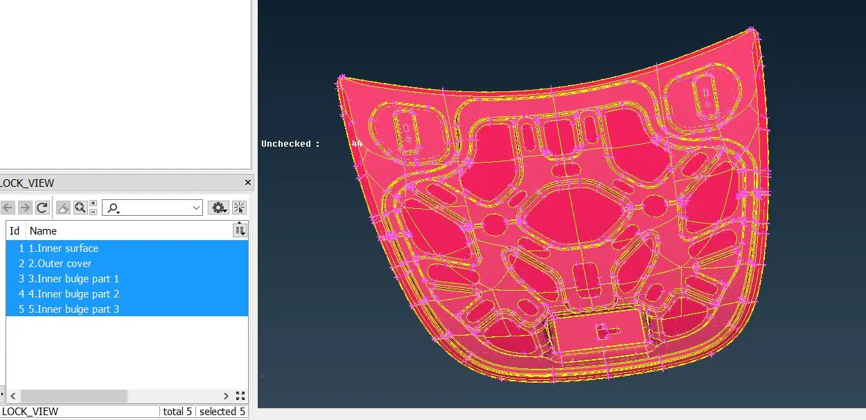
4) After that i measure the thickness of each parts from measure option in utility section and i perform a geometry check operation.Geometric errors can be elimenate by auto fix method but i tried to solve by manually for better understanding of model geometry and good practice on ANSA. During geometry check following errors had been occured.
a) Triple coons :- For removing this error i release triple coons and use topo option for relative coons
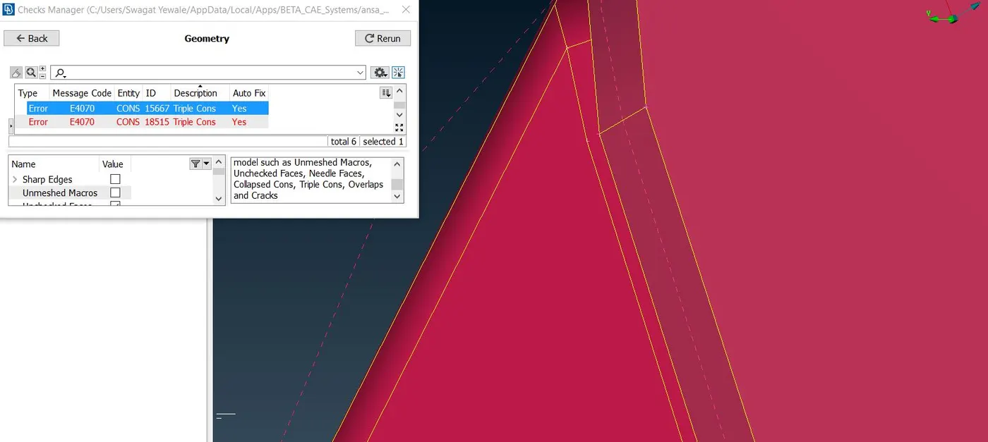
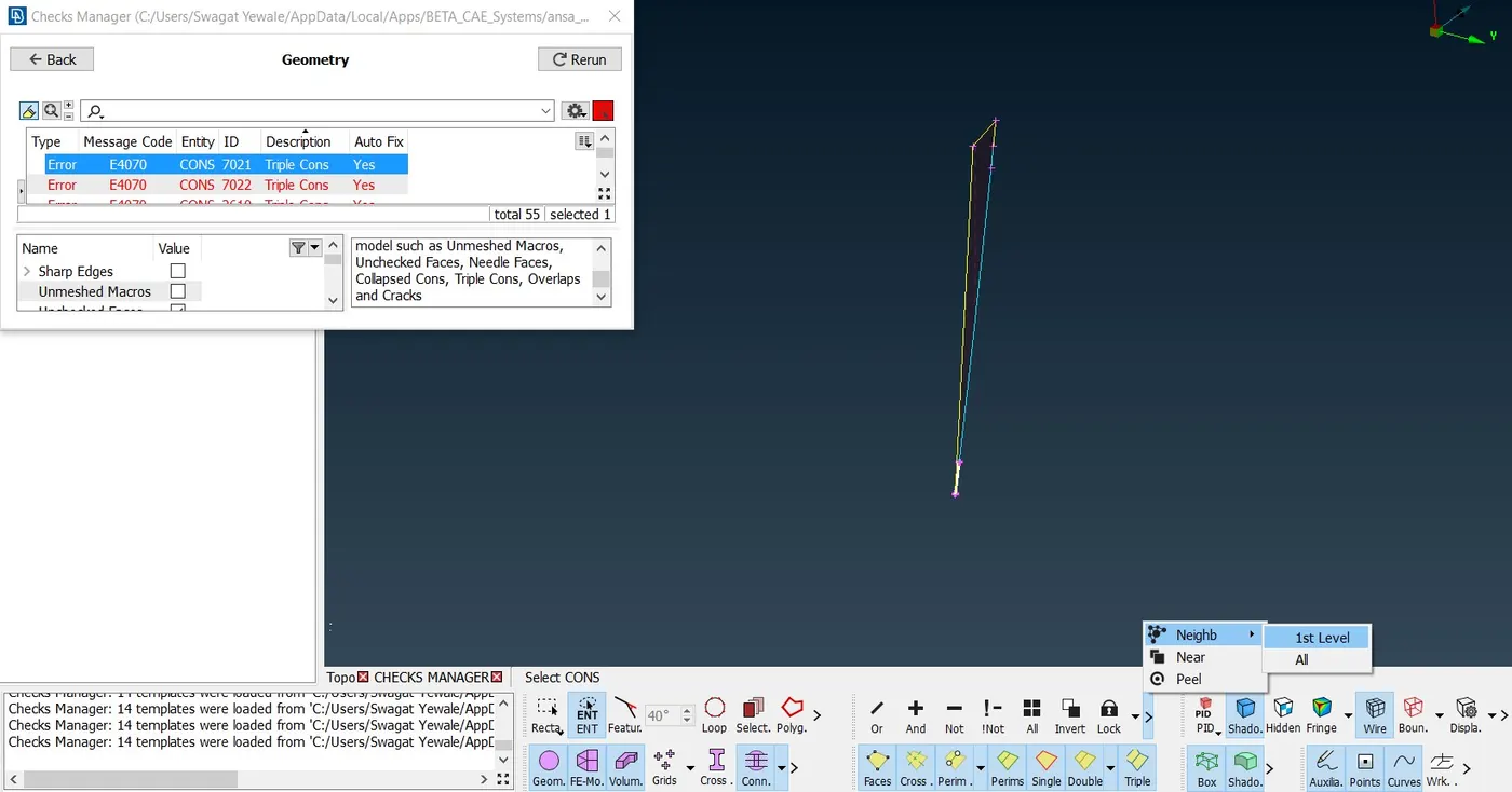
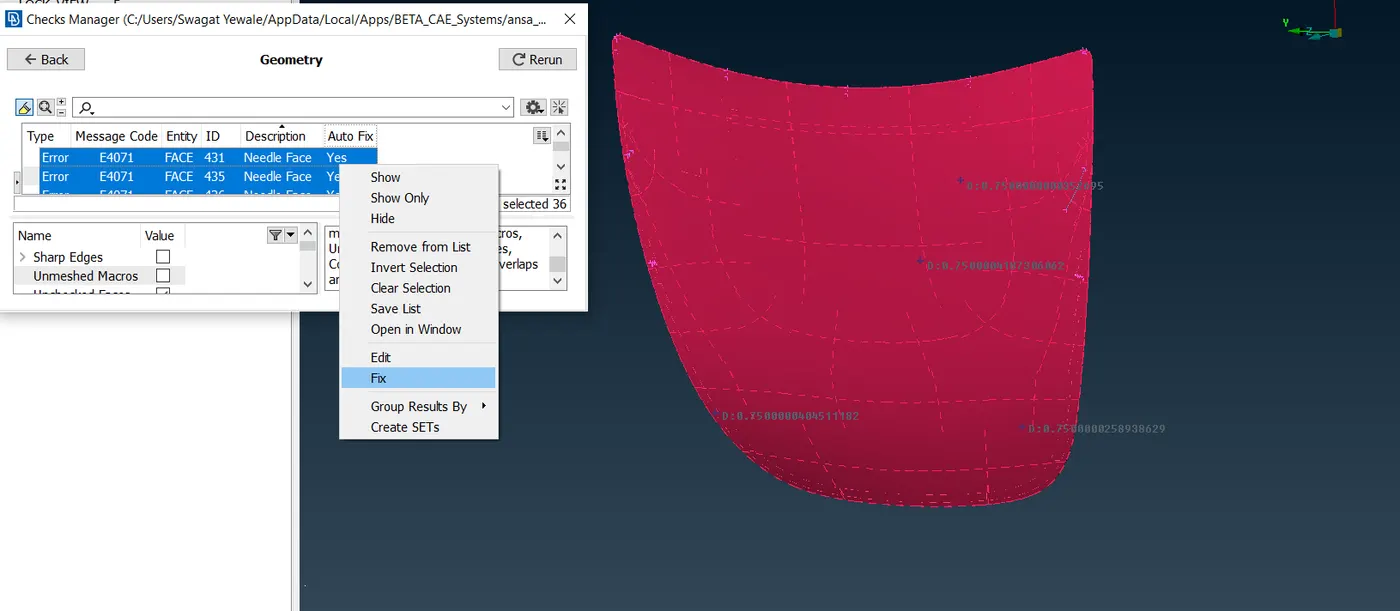
b) Needle face error :- For removing this error i right click on error and fix this error automatically. As this faces are very small to work on it we can neglect this faces by deleting it or auto fix option by ANSA.
c) Crack between coons :- For removing this type error i add new face by Faces>New>Fitted option. For removing this cracks better to use auto fix option because this cracks are very small to identify.
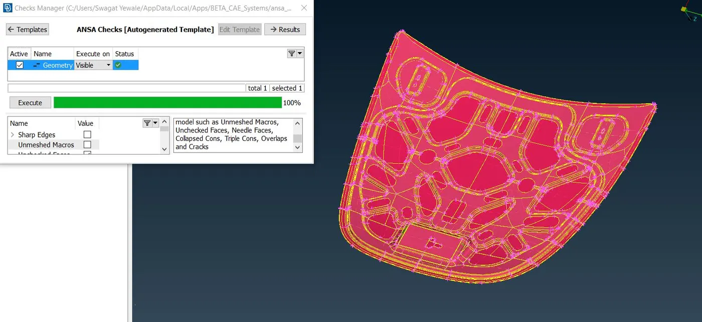
5) After eliminating all these errors in geometry check window on status it shows green tick.this means all geometric cleanup are done we can move further. Below figure shows result of my geometry check.
6) After geometry check i go for mid-surfacing.Mid-surfacing can be done in offset method(manual method) or auto midsurfacing(Mid-surface) . I went for the auto-mid surfacing (Face>Mid-surfacing>Skin) method bacause this method takes very less time as compared to offset(manual) method but drawback of this method is it deleted parent surface without our permission. In offset method there is option for keep the parent surface or not.
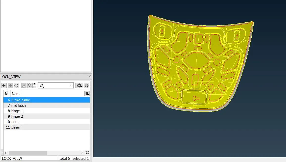
7) After creating mid surface i perform again geometry check while single coons error off. In midsurface perimeter are always songle coon due to it is having no thickness. Also i lock viewed of every midsurface part so that i can work on seperately.
8) After that i went for meshing, also assigning mesh properties and qualty parameters as shown in figure below
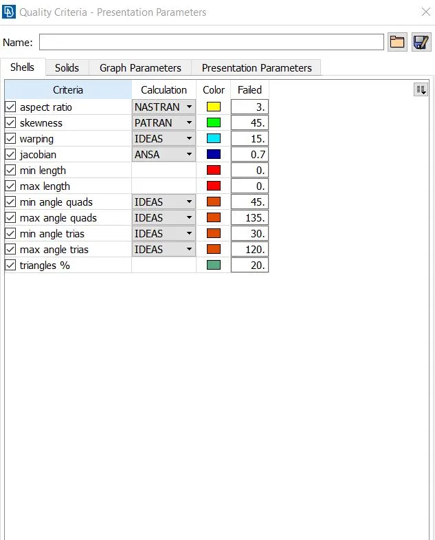
9) before meshing i choose mesh length as 5mm because in problem statement target length is 5mm. and check all points are spaced in 5mm length in between them. also i slide the all holes in model parallel to nearest parameter for good mesh flow purpose.after sliding holes in used marked in option for its lcoking purpose. In some areas i trying to compramise one feuture to save another feutures such as hem bend,fillet,etc in such areas i introduce new cut and deleting existing one for assuring given mesh quality criteria without material loss.Material loss is not at all accepted in preprocessing.
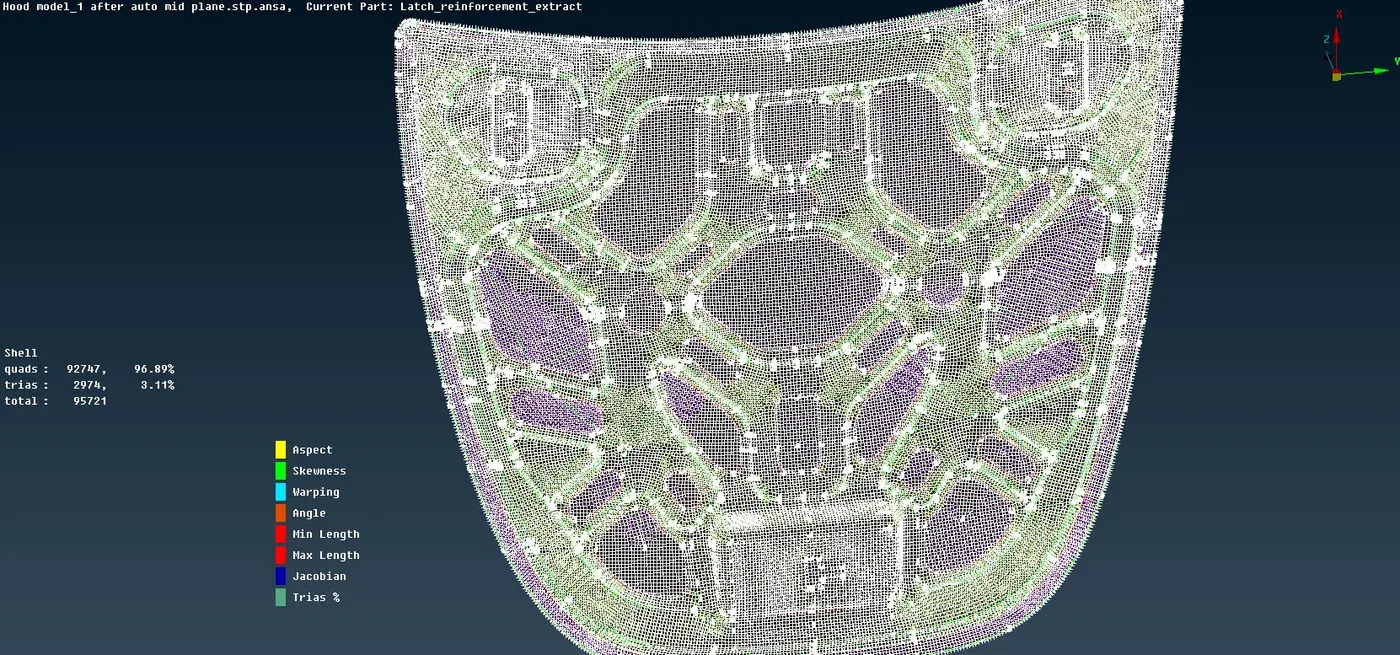
10) After that i perform meshing operation seperately to each part first i perform the complicated part and then move further to easier one.For meshing i use Mesh Generation>Best>select option.For better mesh flow pattern i discritize the part and perform meshing operation and again join those cuts. Creating extra cut makes mesh flow smooth and linear. For good mesh flow i used commands such as Reconstruct,smooth,swap,num+/-,Init,slide,Mark/Unmark,Move,Mv Point,etc.
11) At last i release the model to obtain FE model by using Elements>Release option and apply thickness to mesh by checking the draw shell as solid option. Now model is redy for applying boundary condition and structural analysis.
Learning Outcomes :-
1) We have to perform Topology and geometry cleanup operation as soon as CAD model is imported to ANSA.
2) Topology describes the how elements are bounded and connected to each another
3) For auto mid surface generation need closed volume also in auto mid surface generation parent surface is deleted.
4) Before starting meshing defeuturing is necessary for assuring all quality parameters.
5) Mesh flow has to be perpendicular to each other for getting better mesh flow pattern,discritise model.
6) Waviness pattern is not acceptable in mesh.
7) In mesh flow any tria should not originated with parameter of hole or feuture.
8) Minimize tria in mesh.
9) Smooter mesh flow is better for stree analysis,only finite element model is passed for the analysis.
Conclusion:
Geometry cleanup and topology is done on given sheet model (Car Hood) and model is converted into finite element model for strucural analysis.