Creation of 1D Connectors in Hypermesh.
Aim: Creation of 1D Connectors.
Objective:
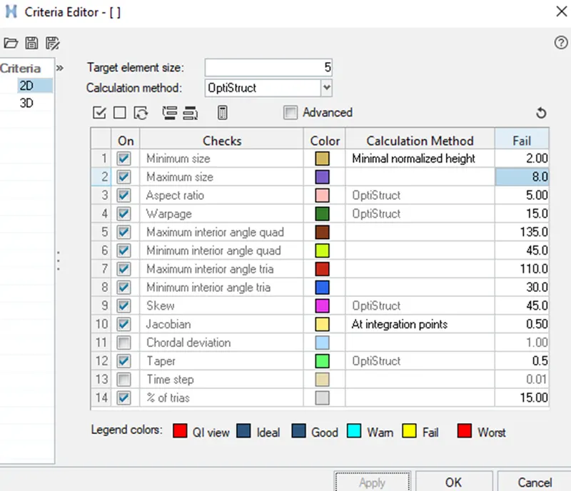
- For this challenge, you will have to mesh the given geometry. Provided below are the quality parameters that you have to follow.
Target Element size - 5 Units
|
S.N |
Quality Criteria |
Value |
|
1 |
Aspect Ratio |
5 |
|
2 |
Skewness |
45 |
|
3 |
Warping |
15 |
|
4 |
Taper |
0.5 |
|
5 |
Min. Length |
2 Units |
|
6 |
Max. Length |
8 Units |
|
7 |
Min angle Quad |
45 |
|
8 |
Max angle Quad |
135 |
|
9 |
Min angle Tria |
30 |
|
10 |
Max angle Tria |
110 |
|
10 |
Tria % |
15 |
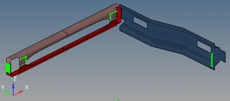
- Create connector and attach the various parts of the given model as given below:
A). Rear_truss_2 & Right_Rail_2:- Bolt Connector
B). Rear_truss_2 & Left_Rail_2:- Bolt Connector
C). Front_truss_2, Front_truss_1 & Left_Rail_1:- Hexa (Adhesive)
D). Right_Rail_2 & Front_truss_1:- Seam-Quad(angled+capped+L)
E). Left_Rail_2 & Front_truss_1:- Quad elements
F). Front_truss_2, Front_truss_1 & Right_Rail_1:- Spot weld with 2 Layers and 5 mm Diameter
G). Right_Rail_1 & Right_Rail_2:- Spot-weld with Rigid Elements
H). Left_Rail_1 & Left_Rail_2:- Spot-weld with Spring Elements
Introduction:
Connectors are a geometric representation of connections between entities. The advantage of connectors is the ability to create multiple connections at a single time. Hundreds or even thousands of connections that would normally have to be created manually one at a time can be mass created, even before the part is meshed. They can be used to create numerous types of connection elements such as:

Entities that are to be connected are referred to as link entities. The connector location can be defined as a node or node list, a geometric point, a line or line list, a surface, or even as elements or tags.
Hypermesh entities currently supported as link entities include ASSEMS, COMPS, ELEMS, SURFS, NODES, and TAGS. Any number of link entities of differing types can be added to a connector in any order. The connector sets the order of link entities during the realization process.
Connectors Terminology
- Link Entities - The entities that are being connected
- Connector Location - Where the entities are linked
- Connector Realization – The creation of the finite element representation of that connector
- Connector State – Whether an FE representation of a connector has been created
- Unrealized - The initial status of the connector entity upon creation
- Realized - The status only if creation of the FE weld representation at the connector was successful
- Failed – The status if creating the FE weld representation at the connector was not successful
- # of Layers – Number of FE weld layers to attempt to generate for the connector
- Connect When – Specifies when the link entity information is added to the connector
Import Model:
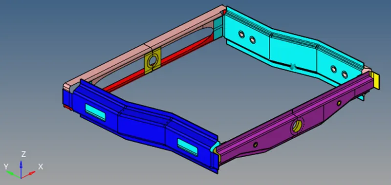
2D Topo View of the geometry shows following features:
Inserting quality criteria as per objective:
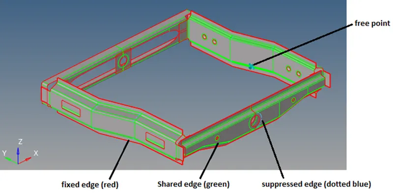
Geometry clean-up topology repair:
- Removing surface fillets
Removing surface fillets smaller than 2 units of radii.
Go to, Geom -> Defeature -> surf fillet

Click on find and then remove the fillets.
In this case we don’t have any fillets smaller than 2 units.
- Toggle
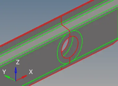
Toggle 'suppressed edge (dotted blue)' to make it ‘shared edge (green)’.
Extracting Mid-Surface:
The model is composed of sheet metal so, no need to extract mid-surface.
Meshing the model:
Go to, 2D -> Automesh
Set, element size as 5 and mesh type as quads. Then select the component and click mesh.

Select the displayed surfaces and click on mesh.
Components meshed individually are shown below. For symmetric components one half of the component could be meshed and then the mesh can be reflected on the opposite side.
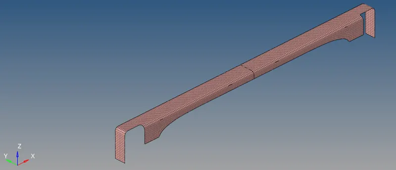
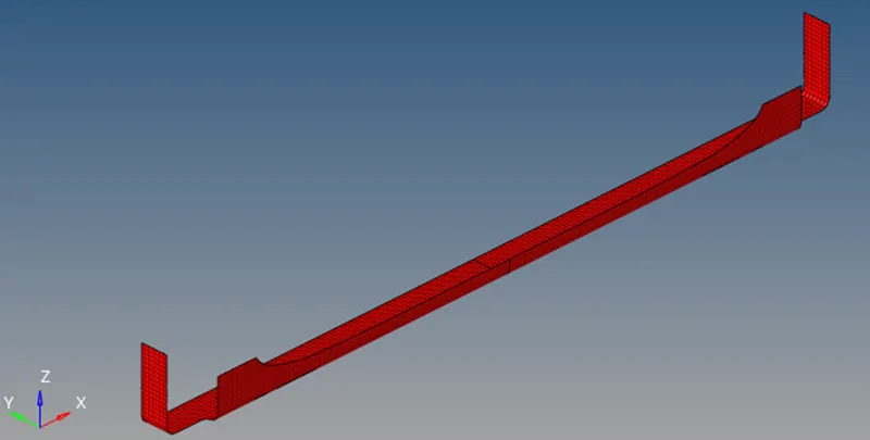
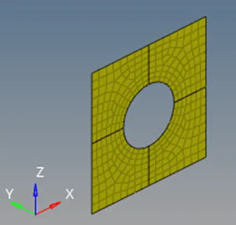
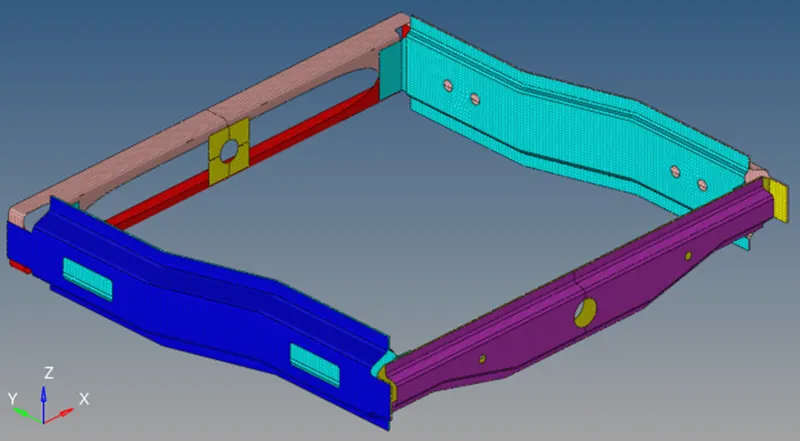
Final meshed model is as shown below:
Assigning Material and Property to each of the components:
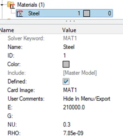
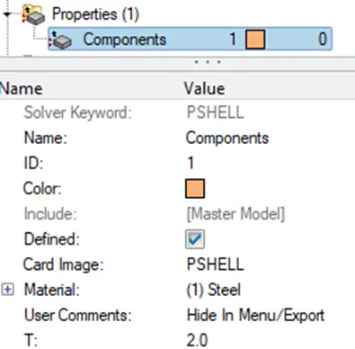
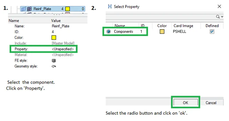
To assign property to a component, select the component, click on ‘property’ and then select the property.
Using connectors to connect two components:
A). Rear_truss_2 & Right_Rail_2:- Bolt Connector
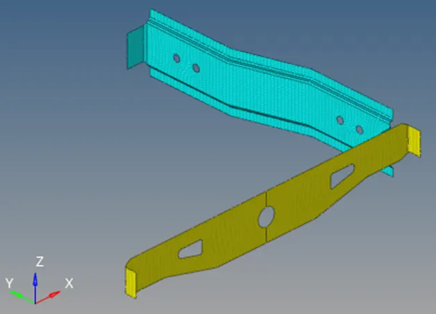
Go to, 1D -> Connectors -> bolts
Choose the following options:
Type = blot (general)
Change ‘consider existing holes only' to ‘create holes if none’

Select the nodes and both components
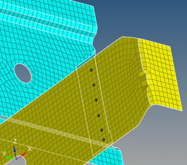
Click on ‘create’.
We get 6 unrealised bolts (shown in red).

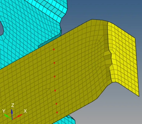
On increasing the tolerance to 5, all the bolts are now realised with RBE2 connectors.
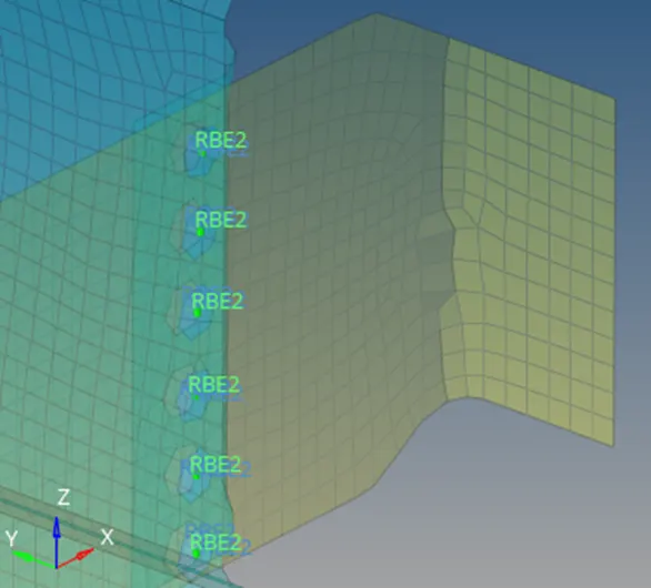
B). Rear_truss_2 & Left_Rail_2:- Bolt Connector
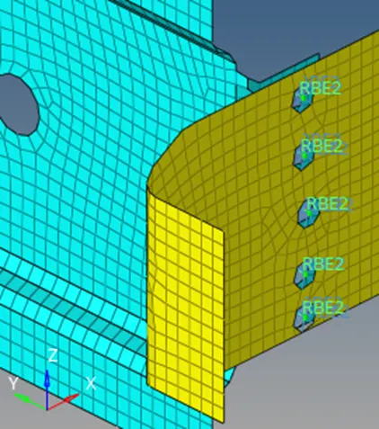
Rear truss and left rail are as shown below.
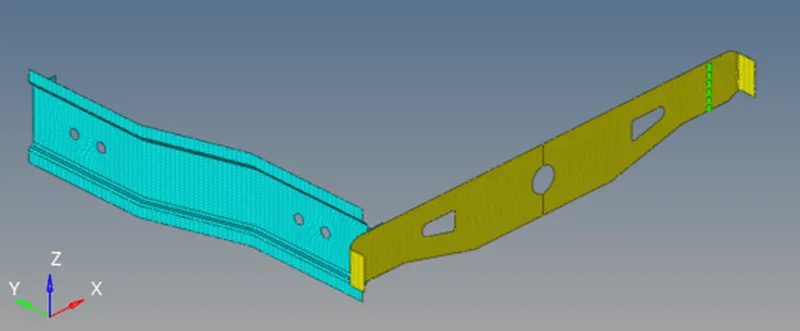
Upon creating bolt connectors, some of the bolts are not realised, this is because the gap between two bolts is not sufficient enough resulting into overlapping of two bolts.
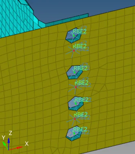
After maintaining sufficient gap, all the bolt connectors are now realised, as shown below.
C). Front_truss_2, Front_truss_1 & Left_Rail_1:- Hexa (Adhesive)
Front truss 2, Front truss 1 and Left Rail 1 is as shown below.

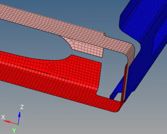
To create ‘adhesive’,
Go to, 1D -> connectors -> area -> type = adhesives

Select elements, components to be connected and tolerance (distance between two components). And click on create.
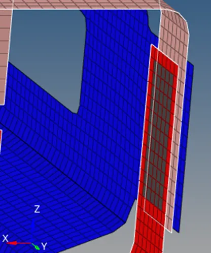

Realised connectors are as shown below,
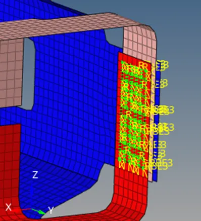
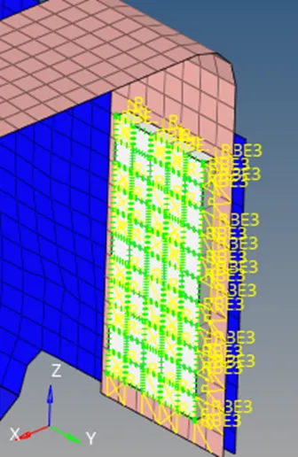
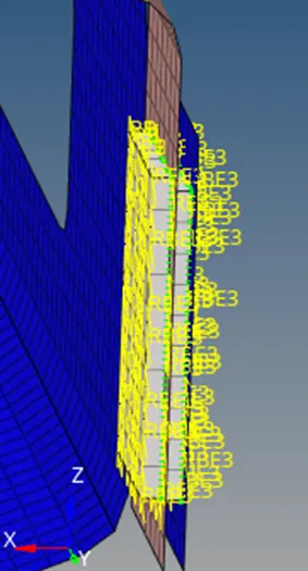
Again, creating ‘adhesive’ between ‘front truss 1’ and Left rail 1’
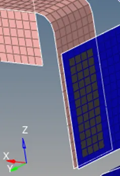
Adhesive connectors are as shown below,
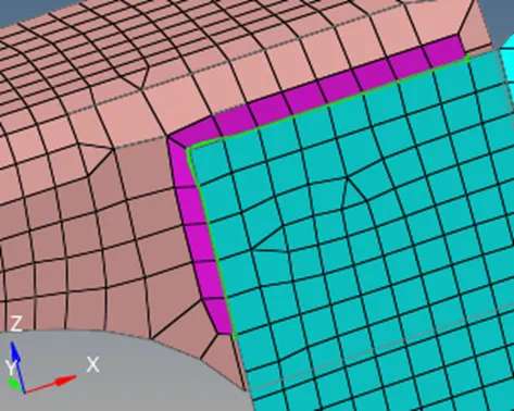
D). Right_Rail_2 & Front_truss_1:- Seam-Quad(angled+capped+L)
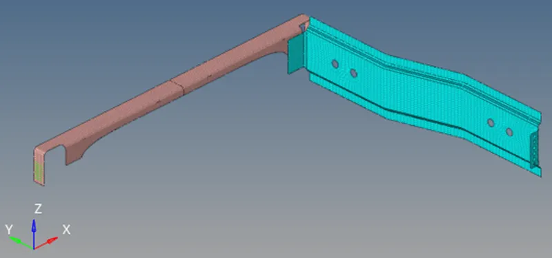
To create seam weld,
Go to 1D -> Connectors -> seam
Select, type = seam-quad (angled + capped + L)

Realised seam weld is as shown below,
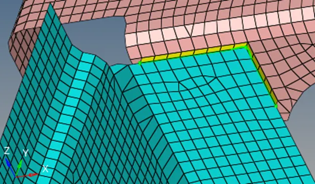
E). Left_Rail_2 & Front_truss_1:- Quad elements
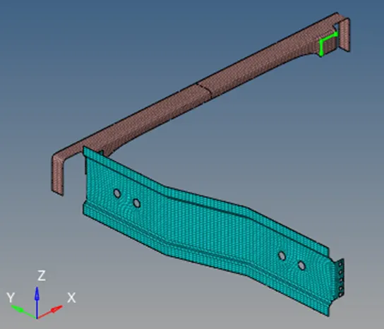
Go to, 1D -> connectors -> seam
Select, type = quads

Then select nodes, components, tolerance and spacing. And click on ‘create’.

Realised connector is as shown below,
F). Front_truss_2, Front_truss_1 & Right_Rail_1:- Spot weld with 2 Layers and 5 mm Diameter
Go to, 1D -> connectors -> spot

Select the nodes, spacing, type, diameter and tolerance. And click on ‘create’.
Note: The node should be selected in a straight line to realise this type of connector.
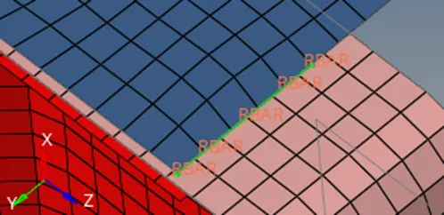

Again, selecting the nodes in straight line and creating the spot weld connectors.
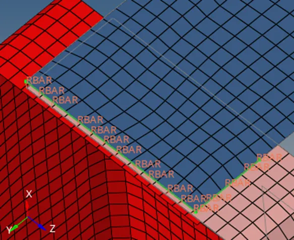
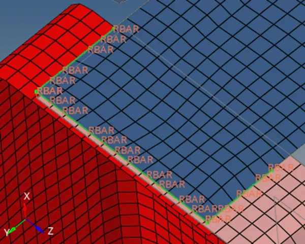
Similarly, the spot weld between front truss 1 and front truss 2 is realised, as shown below,
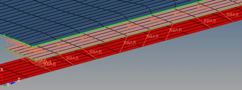
G). Right_Rail_1 & Right_Rail_2:- Spot-weld with Rigid Elements
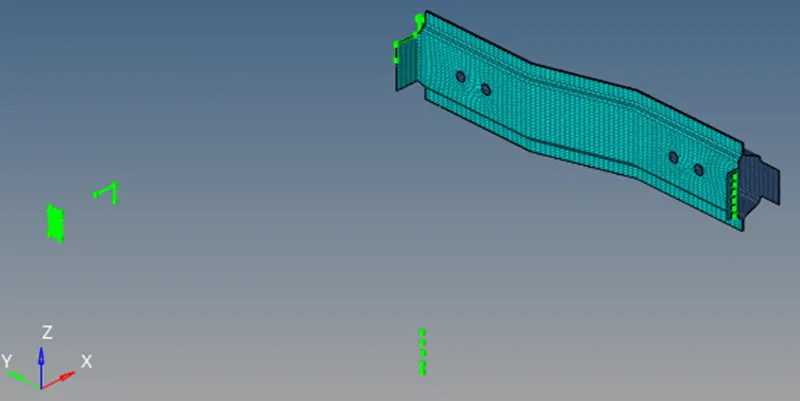
Go to, 1D -> connectors -> spot

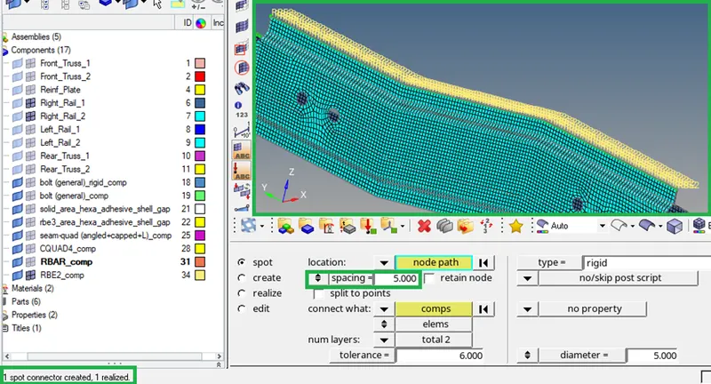
Select the appropriate spacing, tolerance, node path, type etc. and click on ‘create’.
The distance between the nodes (as shown below) is 5 and 3 units. So, we can select spacing to be 5 and tolerance should be greater than or equal to 3.
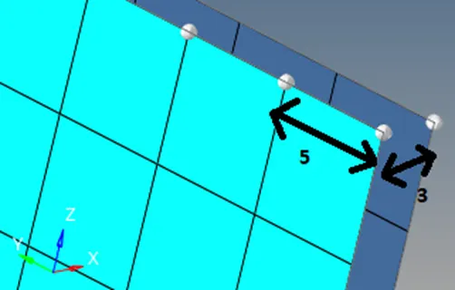
In this case we have chosen, spacing = 5 and tolerance = 6. Hence, the spot weld connector is realised.
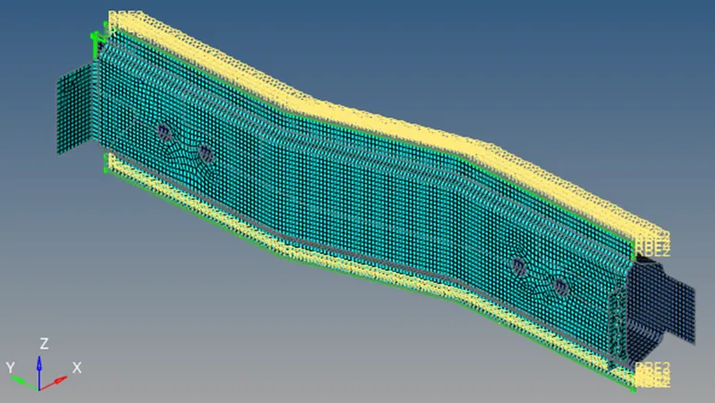
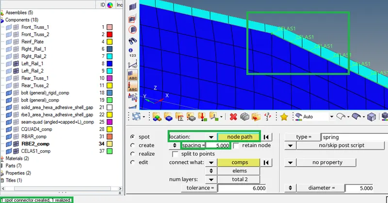
H). Left_Rail_1 & Left_Rail_2:- Spot-weld with Spring Elements
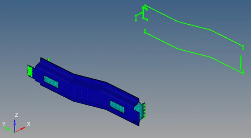
Go to, 1D -> connectors -> spot

Select the appropriate spacing, tolerance, node path, type etc. and click on ‘create’.
The realised spot weld is as shown below,
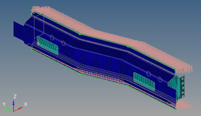
Note:
a. At least two nodes are required to make a spot weld.
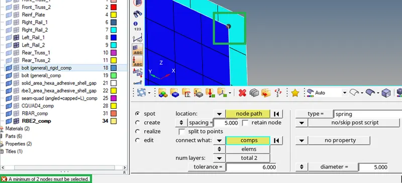
b. Spacing
Spacing is the maximum distance between two nodes. Consider the following example.
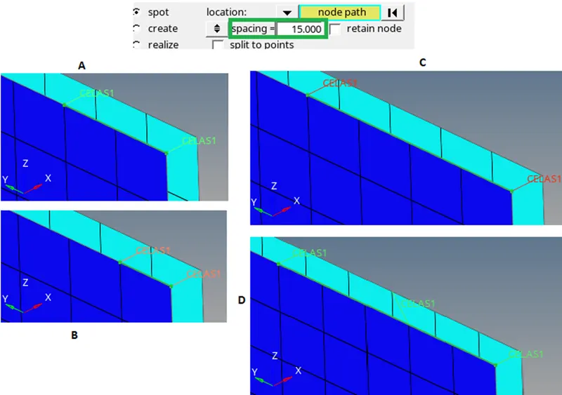
When the spacing is 15, then a distance between two realised connector nodes, at max be 15.
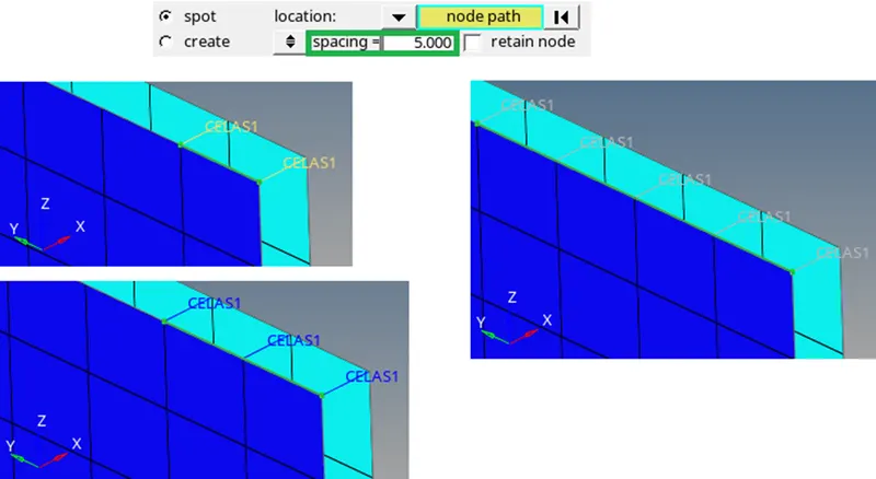
In above example, the distance between two nodes is 5 and spacing is also 5.
c. In this example, distance between the nodes (as shown below) is 5 and 3 units. So, we can select spacing to be 5 and tolerance should be greater than or equal to 3.
Following, error may occur if we increase/ decrease the spacing or while creating connectors at curves/ bends.

In above example spacing is greater than 5. So, the connector is not realised.
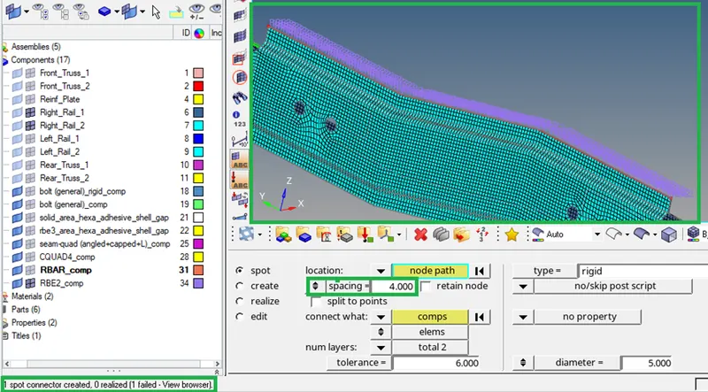
In above example spacing is smaller than 5. So, the connector is not realised.
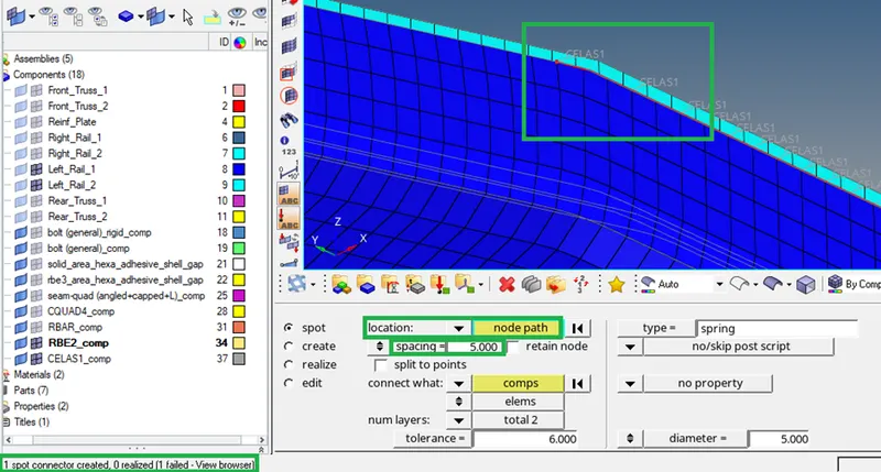
In above example because of curve in the geometry the connector is not realised.
So, resolve the error we can insert the connectors piece by piece, as shown below.
Reference:
ebook-Practical-Aspects-of-Finite-Element-Simulation, Altair