Week 9-Creation of 1D Connectors Challenge
CHALLENGE - 10: Creation of 1D Connectors
AIM:
- To mesh the given geometry by following the mentioned criteria.
- Deploying the different types of connection to the given component.
OBJECTIVE:
- To study about different types of connectors used in FEA.
- To understand about deploying the different types of connection to the given component.
THEORY:
Connectors are geometric entities (not FE) primarily used to create spot and seam welds, but also used to create adhesives, bolts and masses. They are simply a database of information defining specific requests for connections at specific locations.They are a medium to create both solver independent and/or solver dependent connections between geometric and/or FE entities. They can be created interactively or from different master connection files (.xml, .mcf, .vip).
Types of Connectors:
- Spot:
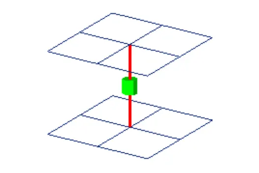
Connections at a point. Spot welds, rivets, etc. - Bolt:
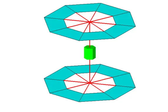 Connections at hole locations.
 - Trim Mass:
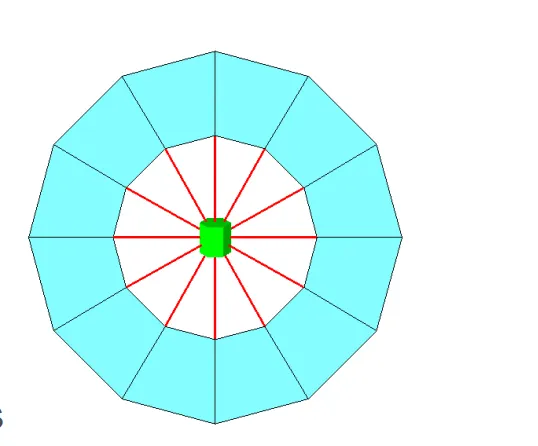
Non-physical mass. Simplification through replacement of parts
with mass only or add mass to existing part. - Seam:
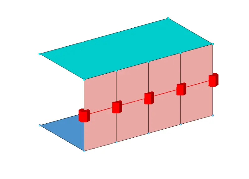
Connections along a length.
Seam welds.
Connects geometry only. - Area:
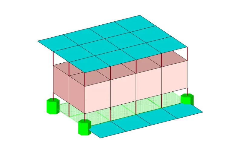
Connection of areas.
Adhesives.
Connectors: Terminology
- Link Entities - The entities that are being connected.
User can explicitly define link entities or specify a search tolerance
Can be components, elements, surfaces, nodes, or tags
Typically components are linked. - Connector Location - Where the entities are linked
Nodes – created at the node location
Points – created at the point location
Lines – created for the line. line may be split into multiple projection locations as specified by the offset, spacing, and density values
Elements – created at the element location (adhesives only)
Surface – created at the surface location (adhesives only) - Connector Realization – The creation of the finite element representation of that connector
Rigids, springs, etc., or custom configurations such as ACMs, CWELDS, etc. - Connector's Module -

1D Page → connectors
- Spot
- Bolt
- Seam
- Area
[create, edit, and realize that style of connectors.] - Apply Mass – adds a mass value to entities.Used to represent mass of parts that are not present in the model.
- FE Absorb – Create new connectors from existing elements of recognizable FE representations of welds, bolts, adhesives, etc.
- Add Links – Add link entities to existing connectors.
- Unrealize – Delete FE representations of welds / bolts / adhesives associated with existing connectors.
- Compare – Checks the MCF against displayed model file.
- Quality – Check for duplicate connectors, combine connectors, check quality of realized elements.
- Connector State –
Whether an FE representation of a connector has been created.
- Unrealized - The initial status of the connector entity upon creation.
Newly created or imported connector before the first realization. Editing the connector definition (i.e. add or delete a link entity from the connector), the connector removes the welds it created, and reverts back to an unrealized state. Manual unrealization.
- Realized - The status only if creation of the FE weld representation at the connector was successful.
- Failed – The status if the creating the FE weld representation at the connector was not successful.
If the creation of the FE representation is unsuccessful (due to low tolerance, insufficient link entities, etc.) the connector icon is displayed as failed (red).
Seam Welds:
The process of joinng the workpiece which are made of similar or dissimilar materials along a continuous seam is known as seam weld. In hypermesh, seam panels under connectors will help to represent the Seam weld connection between the components.
- Weld Angle: Angle between the normal projection of the nodes and slant length of the weld element. It is recommended to defined weld angles between 0 and 90 degree.
- Cap Angle: Angle between the normal of the first slant weld element and its adjacent side element. To define seam weld for 0 to 45 degree cap angle, it is recommended to select ≤ 10 degree and for the 45 - 90 degree cap angle, it is recommended to select ≥ 75 degree.
- Runoff Angle: Angle between the normal of the first slant weld element and its adjacent weld element. It is recommended to define weld angles between 0 and 10 degree.
Spot Weld:
Spot welding is a resistance welding process that is used primarily for welding two or more metal sheets together by applying pressure and heat to the weld area. Heat for the welding process will be obtained from resistance to electric current. Realized spot weld in Hypermesh will represent the connection between the components.
Bolt Connection:
Bolted joints are one of the most common elements in construction and machine design. A connection between structural members made with plates and bolts, as opposed to a riveted or welded construction. In Hypermesh, we use the RBE2 elements to represent the bolt connection, since it has more stiffness.
GIVEN CRITERIA:
For meshing:
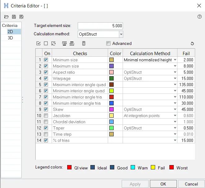
Target Element size - 5 Units
|
S.N |
Quality Criteria |
Value |
|
1 |
Aspect Ratio |
5 |
|
2 |
Skewness |
45 |
|
3 |
Warping |
15 |
|
4 |
Taper |
0.5 |
|
5 |
Min. Length |
2 Units |
|
6 |
Max. Length |
8 Units |
|
7 |
Min angle Quad |
45 |
|
8 |
Max angle Quad |
135 |
|
9 |
Min angle Tria |
30 |
|
10 |
Max angle Tria |
110 |
|
10 |
Tria % |
15 |
The connectors to be attached at the various parts of the given model
1. Right_Rail_2 & Front_truss_1:- Seam-Quad(angled+capped+L)
2. Left_Rail_2 & Front_truss_1:- Quad elements
3. Front_truss_2, Front_truss_1 & Right_Rail_1:- Spot weld with 2 Layers and 5 mm Diameter
4. Front_truss_2, Front_truss_1 & Left_Rail_1:- Hexa (Adhesive)
5. Rear_truss_2 & Right_Rail_2:- Bolt Connector
6. Rear_truss_2 & Left_Rail_2:- Bolt Connector
7. Right_Rail_1 & Right_Rail_2:- Spot-weld with Rigid Elements
8. Left_Rail_1 & Left_Rail_2:- Spot-weld with Spring Elements
9. Rest all the component left Join them with suitable connectors
PROCEDURE:
Step - 1: Importing the Geometry
- The first step is to import the given model. File name: frame_assembly_welding.hm
File → Import → Import Model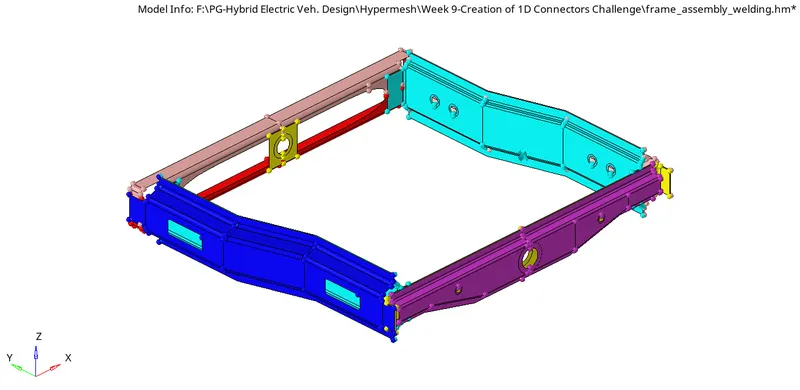
- After importing the model, check for any free edges, dameges in each components. View the geometry as 'By Topo' mode.
Step - 2: Examining geometry and criteria setting
- Before working on the model.We have to check the geometry if there are any errors like
- Damaged Geometry.
- Free edges in unnecessary areas.
- Unnecessary points on the lines.
- Unnecessary Connections and connectivity error.
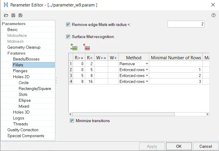
- Before meshing, we have to save/ set criteria as well as parameter settings as per given condition for proper meshing and geometry cleanup.
Preferences → criteria file setting/ Parameter file setting
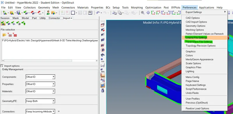
Criteria File:
Parameter file: Here in parameter file, the geometry cleanup option is also activated. So geometry cleanup will be done while batch meshing.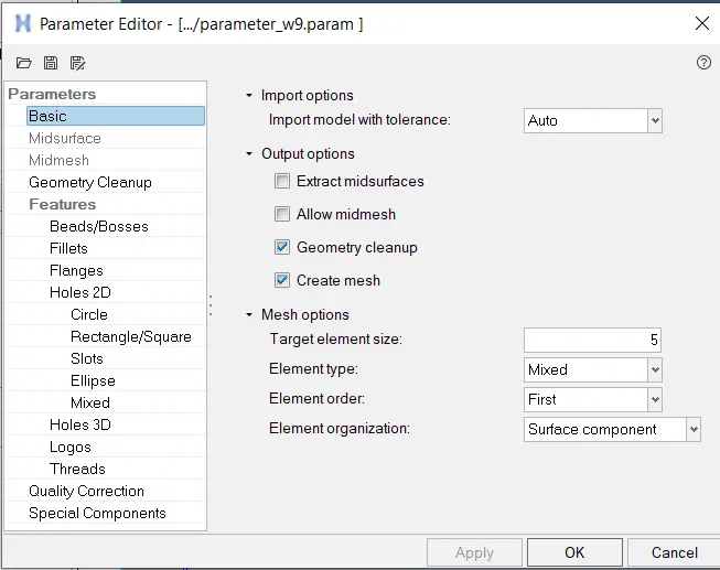
- To assign a property,Right click on the feature tree panel/right click → create → property.
- Do the same thing for the material also.
- After creating property and material.Select the property and give the material which you have created and thickness to the property.
- And then go and assign the property to the component which you have exracted the mid surface from it..
Here the mid-surface is given for each geometry.
Step - 3: Meshing
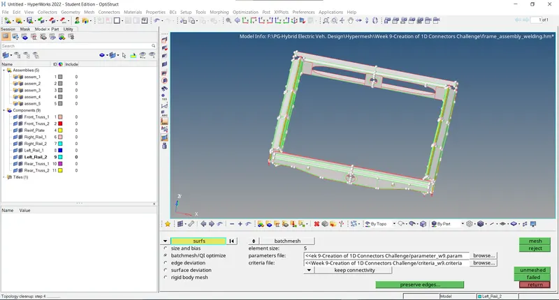
- We can perform automesh or batchmesh. Here we choose batchmesh. It will reduce the time for meshing. The geometry clean-up also take place while batch meshing, because we have given those settings in parameter file.
- Before meshing we should create midsurface for each component. But here we are already given with midsurface. So, proceed for meshing after checking geometry.
- Batch meshing is used here for meshing.
2D → automesh → batchmesh/ QI optimize → select criteria and parameter file which are already saved → select surface displayed → mesh
Step - 4: Mesh Quality checking
- The next step is to check the mesh flow, tria direction, free edge element, geometry capturing etc. Also check for duplicates, edges, penetration, normals etc. from 'Tool' tab.
- Also use rebuild mesh, clean-up settings, replace nodes and quick edit tab for mesh flow and quality adjustment.
2D → rebuild → select element → rebuild
2D → qualityindex → cleanup tools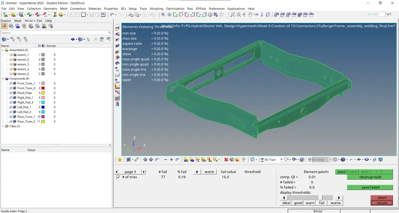
Step - 5: Deploying connection
- Before giving connection's to the components,Load the connector browser from the user interface panel. Open the connectors browser by,
- View → Browsers → HyperMesh → Connector
Use the Connector browser to view and manage connectors after creating connectors. Always check mesh after deploying connectors. If any area of mesh is disturbed by connector, remesh and adjust those areas.
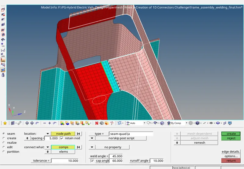
1. Right_Rail_2 & Front_truss_1:- Seam-Quad(angled+capped+L):
- Create connectors between the shell mesh of the Right_Rail_2 and Front Truss_1.
- Select 1D/2D → Connectors → Seam
- Now select the location, where the weld has to be created, by clicking the 'Node list' by path option.
- Tick checkbox of 'retain node' option, to retain the position of the nodes, while creating and realizing a connector.
- Specify the 'spacing' value as target element size and select the components which are to be joined by clicking the 'comps' option. specify the tolerence based on the distance between two component (Here we select as 10). Give weld, cap and runoff angle.
- Select the type as 'seam-quad(angled+capped+L)'. Then, click on the button 'create' to create seam weld.
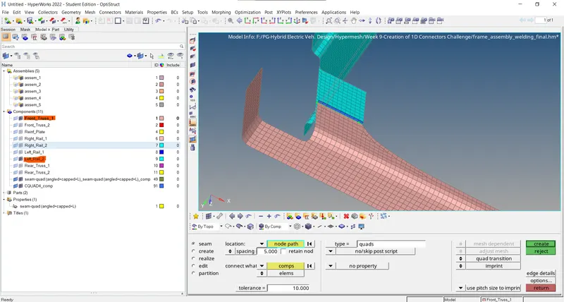
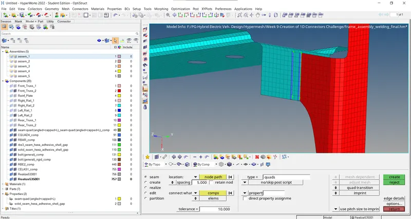
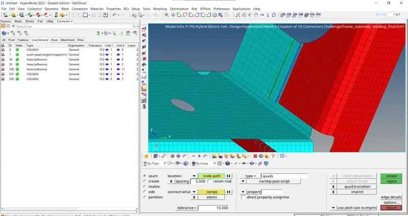
2. Left_Rail_2 & Front_truss_1:- Quad elements:
- Select 1D/2D → Connectors → Seam
- Now select the location, where the quad elements have to be created, by clicking the 'Node list' by path option.
- Tick checkbox of 'retain node' option, to retain the position of the nodes, while creating and realizing a connector.
- Specify the 'spacing' value as target element size and select the components which are to be joined by clicking the 'comps' option. specify the tolerence based on the distance between two component (Here we select as 10).
- Select the type as 'quads'. Then, click on the button 'create' to create quad elements.
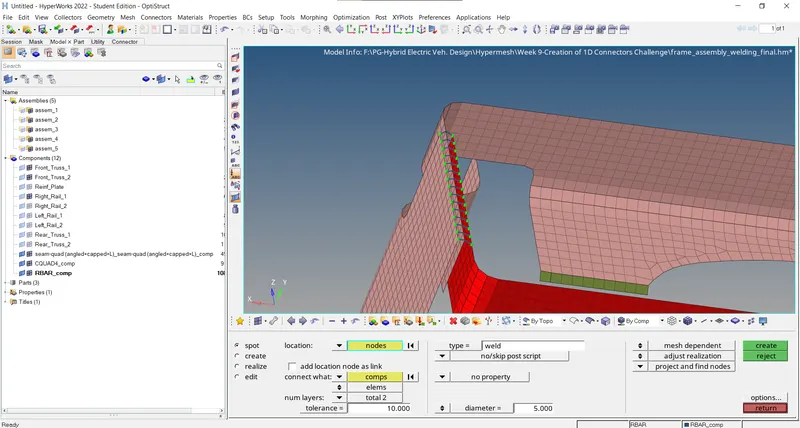
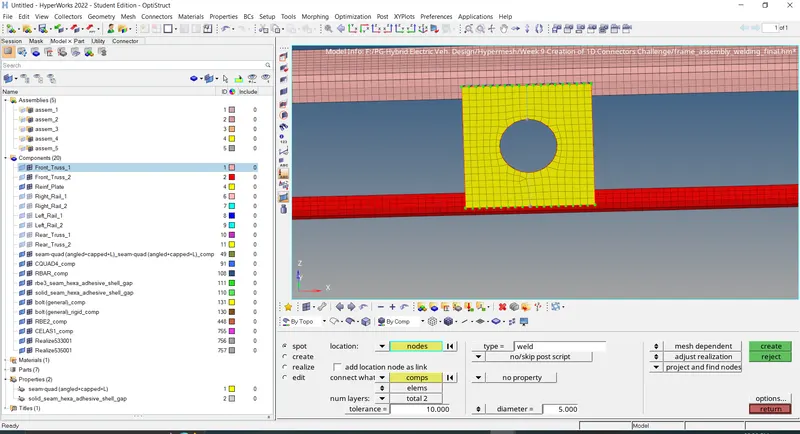
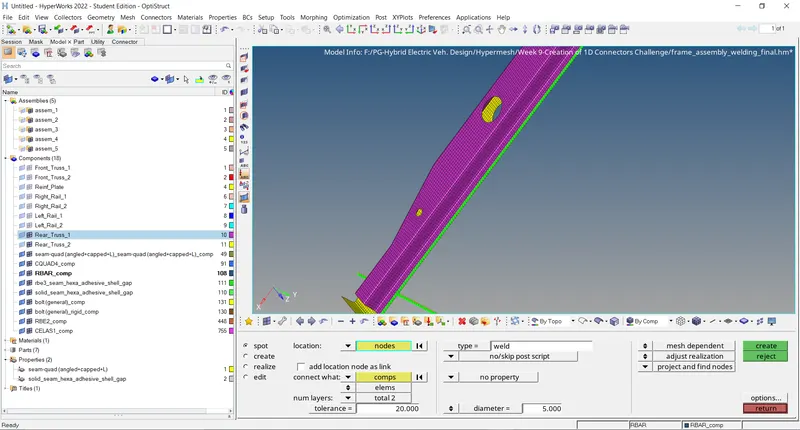
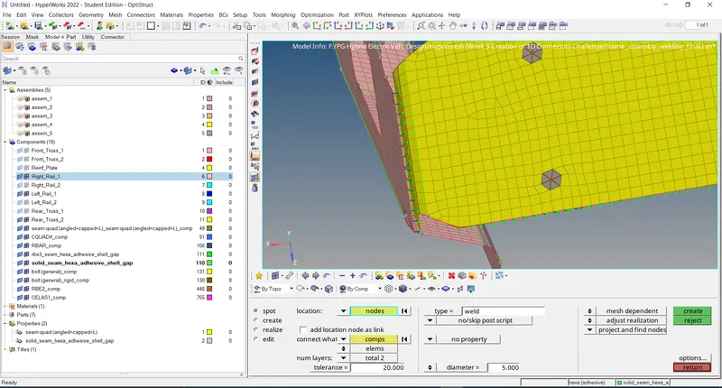
3. Front_truss_2, Front_truss_1 & Right_Rail_1:- Spot weld with 2 Layers and 5 mm Diameter:
- Select 1D/2D → Connectors → Spot
- Now select the location, where the weld has to be created, by clicking the 'Node list' by path option.
- Tick checkbox of 'retain node' option, to retain the position of the nodes, while creating and realizing a connector.
- Specify the 'spacing' value as target element size and select the components which are to be joined by clicking the 'comps' option. specify the tolerence based on the distance between two component (Here we select as 10).
- Select the number of layers(Number of Components) to be welded, under the 'num layers' option. Also specify the diameter given.
- Select the type as 'weld'. Then, click on the button 'create' to create spot weld.
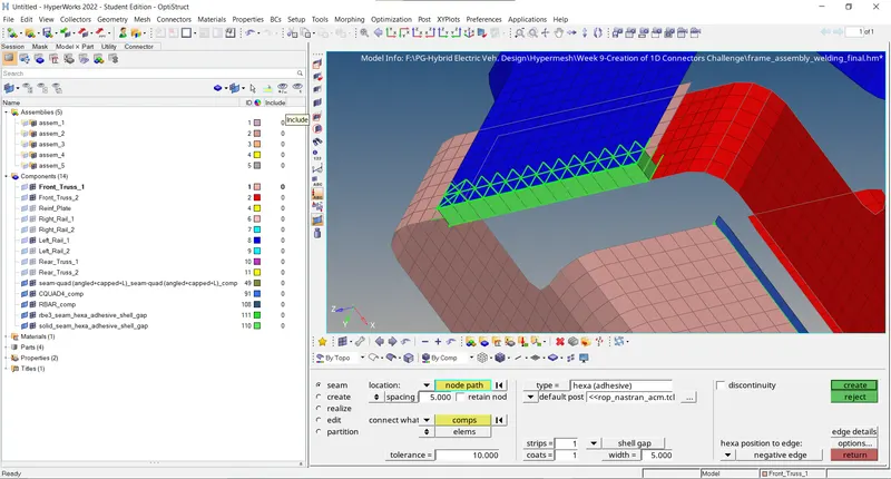
4. Front_truss_2, Front_truss_1 & Left_Rail_1:- Hexa (Adhesive):
- Select 1D/2D → Connectors → Seam
- Now select the location, where the Hexa (Adhesive) have to be created, by clicking the 'Node list' by path option.
- Tick checkbox of 'retain node' option, to retain the position of the nodes, while creating and realizing a connector.
- Specify the 'spacing' value as target element size and select the components which are to be joined by clicking the 'comps' option. specify the tolerence based on the distance between two component (Here we select as 10). If needed, we can specify strips and coats as well.
- Select the type as 'hexa (adhesive)'. Then, click on the button 'create'.
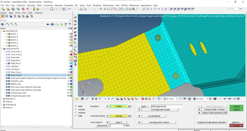
5. (Rear_truss_2 & Right_Rail_2) and (Rear_truss_2 & Left_Rail_2):- Bolt Connector
- In order to create a Bolt connection, if we had hole present in the components, we have to locate a centre node. Else there is option create hole automatically while deploying bolt.
- Now select 1D/2D → Connectors → bolt option.
- Under 'location', select the node, where you want the bolt.
- Then select the components, which are to be connected.
- Select the number of layers to be bolted, under 'num layers' option.
- Specify the 'tolerance' value, based on the distance between the two components. Here there is no hole, so choose create hole, if none.
- Select bolt type as 'bolt (general)'. Click on the 'create' button.
- After bolt creation, the mesh will be distorted. So correct it manually by using rebuild, element edit tool etc.
Rear_truss_2 & Right_Rail_2
Rear_truss_2 & Left_Rail_2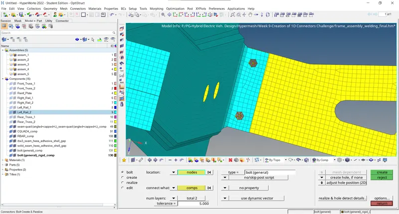
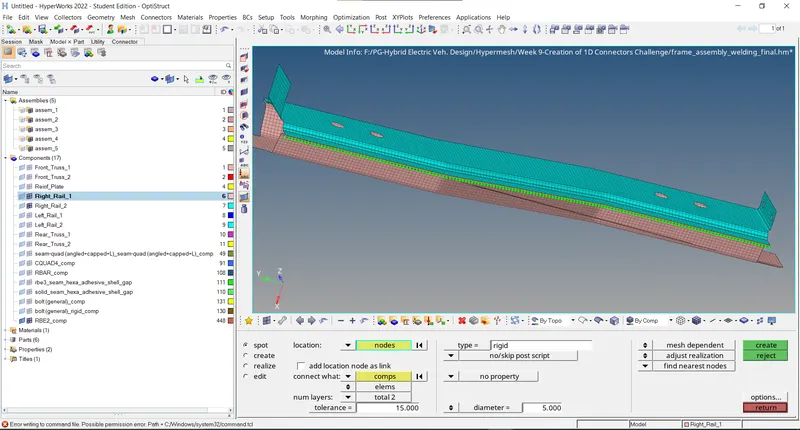
6. Right_Rail_1 & Right_Rail_2:- Spot-weld with Rigid Elements:
- To create Spot weld with Rigid Elements between the components, use the option,
1D → connectors → spot - Now select the location, where the weld has to be created, by clicking the 'Nodes' by path option.
- Tick checkbox of 'retain node' option, to retain the position of the nodes, while creating and realizing a connector.
- Select the components which are to be joined by clicking the 'comps' option. Specify the tolerence based on the distance between two component (Here we select as 10 or 15).
- Select the number of layers(Number of Components) to be welded, under the 'num layers' option. Also specify the diameter given.
- Select the type as 'Rigid'. Then, click on the button 'create' to create spot weld with rigid element.
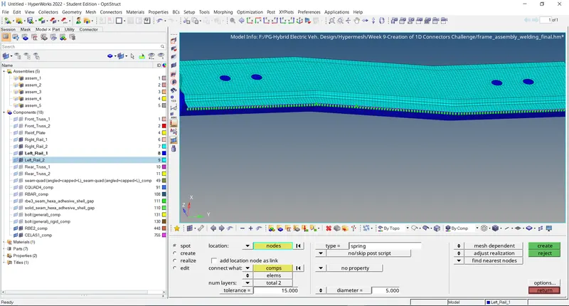
7. Left_Rail_1 & Left_Rail_2:- Spot-weld with Spring Elements:
- To create Spot weld with Rigid Elements between the components, use the option,
1D → connectors → spot - Now select the location, where the weld has to be created, by clicking the 'Nodes' by path option.
- Tick checkbox of 'retain node' option, to retain the position of the nodes, while creating and realizing a connector.
- Select the components which are to be joined by clicking the 'comps' option. Specify the tolerence based on the distance between two component (Here we select as 10 or 15).
- Select the number of layers(Number of Components) to be welded, under the 'num layers' option. Also specify the diameter given.
- Select the type as 'Spring'. Then, click on the button 'create' to create spot weld with rigid element.
8. Rest all the component left, Joined with suitable connectors:
The connectors are deployed at different location left by choosing the above mentioned methods.
- Front truss_1, front truss_2 and reinf plate: spot weld
- Front truss_2 and left rail_2: Quad element
- Front truss_2 and right rail_2: Quad element
- Left_Rail_1 & Left_Rail_2: spot weld with spring element
- Rear truss_1 and rear truss_2: Spot weld
- Right rail_1 and rear truss_2: Spot weld
Step - 6: Model Checking
- Quality Index: 2D → qualityindex,
Check for elements failing quality criteria after deploying connection.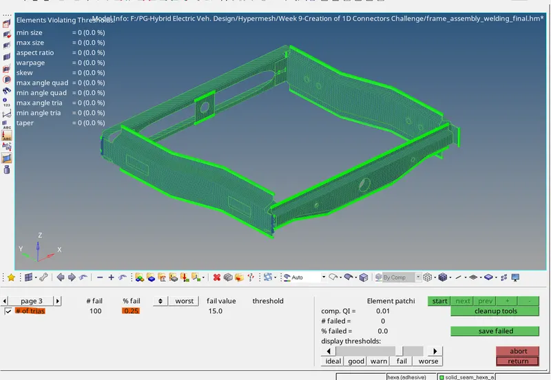
- Check for edges: It is checking element connectivity.
- Find edges of the model for perfection.
Tools → edges → select element dispalyed → find edges,
If no error noticed, delete edges . Click on return.
otherwise, you can click on preview equivalence and equivalence and try to fill that. If it not solve the issue, we have to use replace node tool.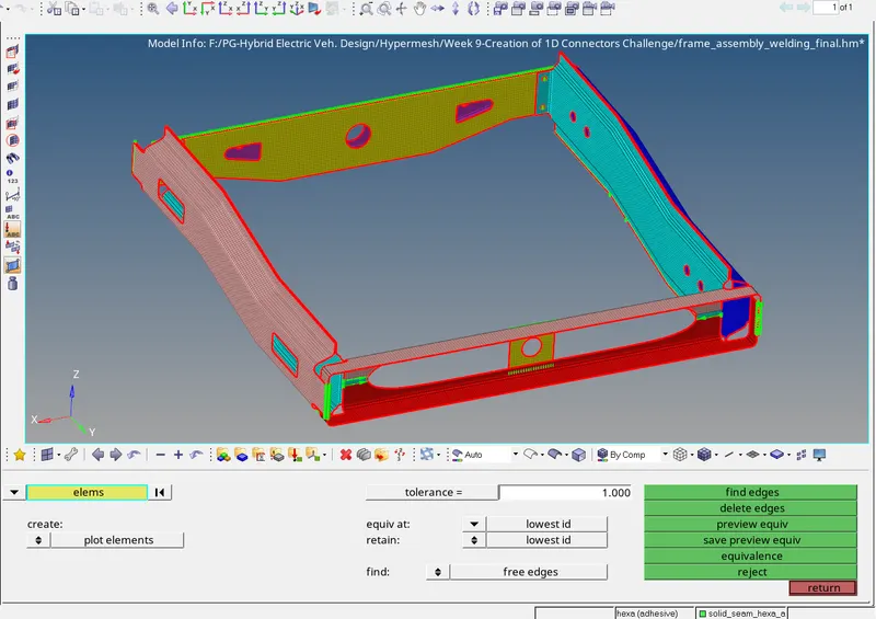
- Element to surface edge check: To check how the element is captured the surface geometry.
mesh → check → elements → comparison → click on element tab shown in source entity → Select element displayed → Proceeds → click surface tab in the target entity → select surface displayed → Tolerance = 0.2 → Run.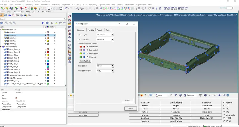
The yellow and pink color in mesh is okay. If there is defect, we used project tool to rectify it
- Check for Normals, Penetration & intersection:
- Tools → Normals → display → we can choose colordisplay or vector display.
The defected element's normals are reversed using the same tool by selecting the element. - Tools → penetration → select element displayed → check
Penetration is defined as the overlap of the material thickness of shell elements, while intersection is defined as elements that actually pass completely through one another.
RESULT:
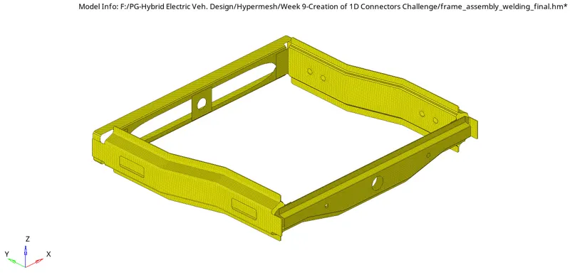
- Generated mesh on the given geometry as per the criteria using HyperMesh.
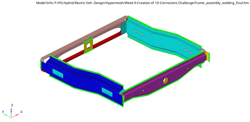
- Different connectors are deployed at different location of the given geometry components.
- Final Meshed model with connectors:
QualityIndex of final model:
CONCLUSION:
This challenge helped me to understand about various 1D connectors available in HyperWorks and their uses. This challenge is also very useful for getting knowledge about deploying connectors, various options available in connector tool option etc.