Week 2- 2R Robotic Arm Challenge
PROGRAM: Simulation of forward kinematics of a 2R Robotic Arm
AIM:
To Write a program in Matlab to simulate the forward kinematics of a 2R Robotic Arm and make a video of it.
THEORY:
A robotic arm is a type of mechanical arm, usually programmable, with similar functions to a human arm. The links of such a manipulator are connected by joints allowing either rotational motion or translational (linear) displacement.
A 2R robotic arm represents a robotic arm with two rotations. i.e. it has two links which rotate or work over a two-dimensional plane with each of links having a single degree of freedom.
If we are able to find out how the robotic arm move, we could specify the application of a robot. That is we can find out it's workspace (The possible location the robot can reach).
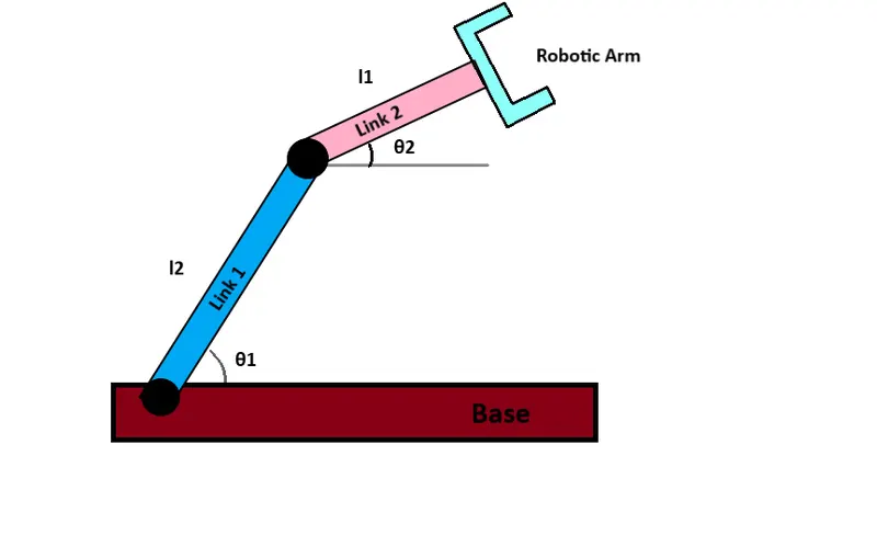
For a 2R Robotic Arm, there are two links and two rotational joints. Link 1 makes an angle `theta_1`with the x-axis and link 2 makes `theta_2`with the x-axis. Let's assume the link length to be `l_1 and l_2` respectively. First we need to specify the position of the manipulator if `theta_1 and theta_2` are given/known.
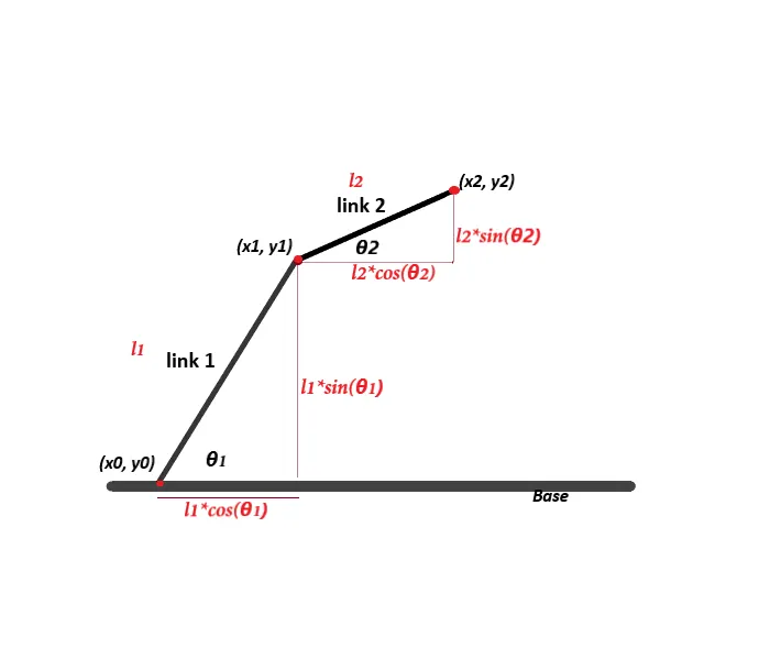
The starting and end points of link 1 and 2 are marked as shown in figure.
The starting point of link 1 is marked as `(x_0, y_0)`and is taken as (0, 0). The end point of link 1 and starting point of link 2 are same, i.e. `(x_1, y_1)`. From above figure,
`x_1 = l_1*costheta_1 and y_1 = l_1*sintheta_1`.
Similarly the end point of link 2 is `(x_2, y_2)`. i.e. `x_2 = x_1+l_2*costheta_2 and y_2=y_1+l_2*sintheta_2`. With these three points we could do the program in matlab.
CODE:
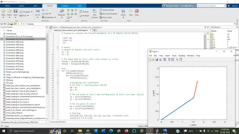
% Program to simulate the forward kinematics of a 2R Robotic Arm by Matlab

 clear all
 close all
 clc

% inputs
% Lengths of Robotic arm link 1 and 2
l1 = 2;
l2 = 1;

% The angle made by link 1 and 2 with respect to x-axis
theta1 = linspace(0,90,10);
theta2 = linspace(0,90,10);

k=1;
for i=1:length(theta1)
    THETA1=theta1(i);
    for j=1:length(theta2)
        THETA2=theta2(j);

        % Assigning link coordinates
        % For link 1- starting point (x0,y0)
        x0 = 0;
        y0 = 0;

        % The end point of link 1 and starting point of link 2 are same- (x1,y1)
        x1 = l1*cosd(THETA1);
        y1 = l1*sind(THETA1);

        % The end point of link 2
        x2 = x1+l2*cosd(THETA2);
        y2 = y1+l2*sind(THETA2);

        % Plotting
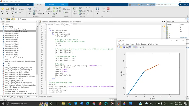
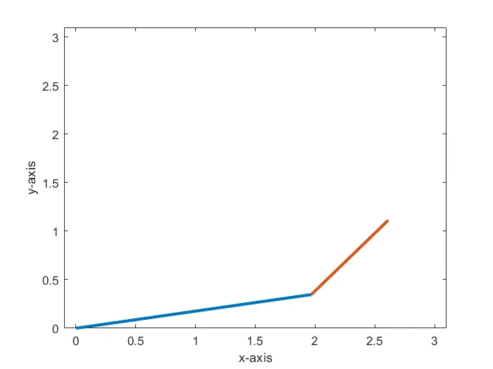
        plot([x0 x1], [y0 y1], [x1 x2], [y1 y2], 'LineWidth',2.5)
        axis([-0.1 3.1 0 3.1])
        xlabel('x-axis')
        ylabel('y-axis')
        pause(0.2)
        M(k)=getframe(gcf);
        k=k+1;
    end
end
% Making the Simulation video
movie(M)
videofile= VideoWriter('forward_kinematics_2R_Robotic_Arm.avi','Uncompressed AVI');
open(videofile)
writeVideo(videofile,M)
close(videofile)
EXPLANATION:
In the above program code, first we need to specify the inputs that we need to provide. Initially we provide command to store the value of length of link 1 and 2 in `l_1 and l_2`.
Then we need the angular movements of link 1 and 2, for simulation purpose we provide ten value each for `theta_1 and theta_2` by using linspace command. i.e.,
Then the command to assign link coordinates are provided. We take the starting point of link 1 as origin, i.e.