Week 9-Creation of 1D Connectors Challenge
week9 challenge
objective:mesh the given components at given parameters and create the connectors on the components and Attach the various parts of the given model .
procedure:
step1 :
- mesh the all component at given parameters and
- check quality creteria and fix those element.
step2:
create the connectors on the component at given model
- seam quad (angled+capped+L) for the Right Rail 2 & Front truss 1
- isolate the right rail2 and front truss 1
- select the connector option from 1D/2D menu .
- now select the seam option and select the where want create connector by selecting the node list or line list.
- then select the type of weld that anlged +capped+ L shaped and spacing depends on element size and the tolerence.
- then select the components right rail2 and front truss 1.
- select the create option and returns it.

above fig1 shown is tool path way.
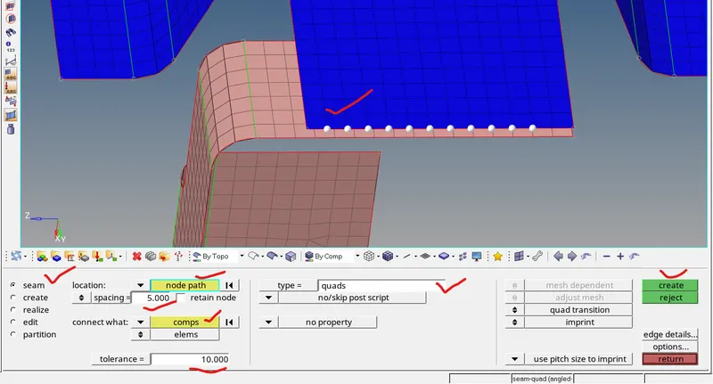
above fig2 is selecting the node list.
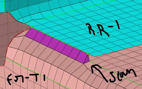
above fig3 is seam weld is created between front truss1 and right rail 2.
2.Left Rail_2 & Front truss 1:- Quad elements
similar procedure for quad element like we did for the quad (angled+capped+L)
- isolate the Left Rail_2 & Front truss 1
- select the connector option from 1D/2D menu .
- now select the seam option and select the where want create connector by selecting the node list or line list.
- then select the type of weld that quad and spacing depends on element size and the tolerence.
- then select the components Left Rail_2 & Front truss 1
- select the create option and returns it.

above fig shown is for tool path way
above fig is selcect the node list.
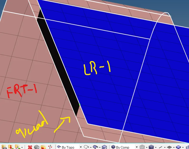
above fig is quad weld created.
3. Spot weld with 2 Layers and 5 mm Diameter for Front_truss 2, Front_truss_1 & Right_Rail 1:
- isolate the Front_truss 2, Front_truss_1 & Right_Rail 1
- select the connector option from 1D/2D menu .
- now select the spot option and select the where want create connector by selecting the node list or line list.
- then select the type of weld that is spot weld with 2 layer and 5mm diameter and give the serch tolerence 10.
- first select the components Front_truss 2 and Front_truss_1
- select the create option and returns it.
- then select the node list for front truss 1 and right rail 1 and select the component and create it.

above fig is tool path way for spot weld.
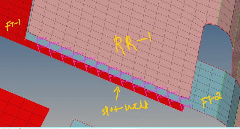
above fig is connectors are created on the component.
4.Hexa (Adhesive) for the components Front truss_2, Front truss_1 & Left Rail 1:
- isolate the Front_truss 2, Front_truss_1 & left Rail 1
- select the connector option from 2D menu .
- now select the area option and select the where want create connector by selecting the elements.
- then select the type of adhesive that is hexa adhesives and give the serch tolerence 10.
- first select the components of Front_truss 2 and Front_truss_1
- select the create option and returns it.
- then select the elemeny for front truss 1 and left rail 1 and select the component and create it.

above fig is for toolpath way for adhesives:
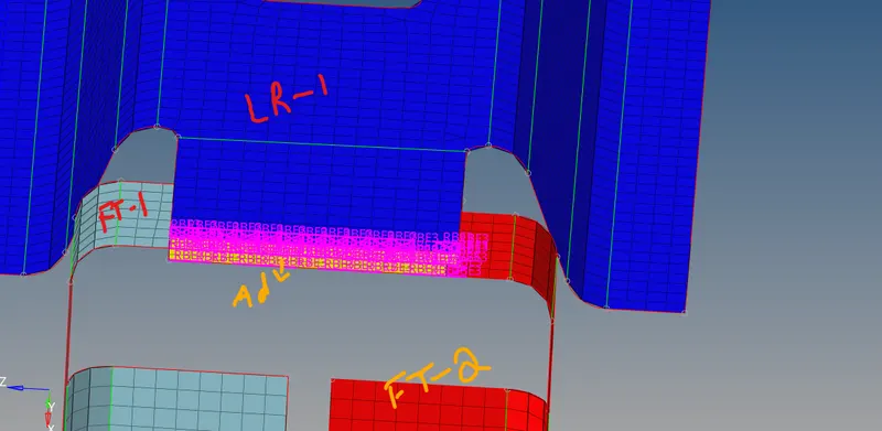
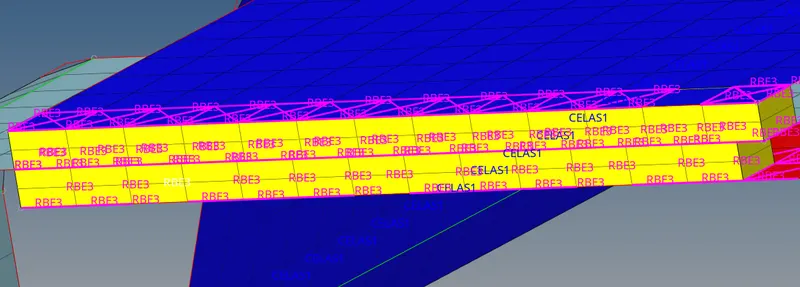
above fig is adhesives is created on the components.
5.bolt connectors for Rear_truss_2 & Right_Rail_2
- isolate the Rear truss 2 & Right Rail 2
- select the connector option from 1D/2D menu .
- now select the bolt option and select the where want create connector by selecting the node list .
- then select the type of bolt and search tolerence is 10.
- then select the components Rear_truss_2 & Right_Rail_2 and then click the create the option.

above fig is for tool pathway for Rear_truss_2 & Right_Rail_2.
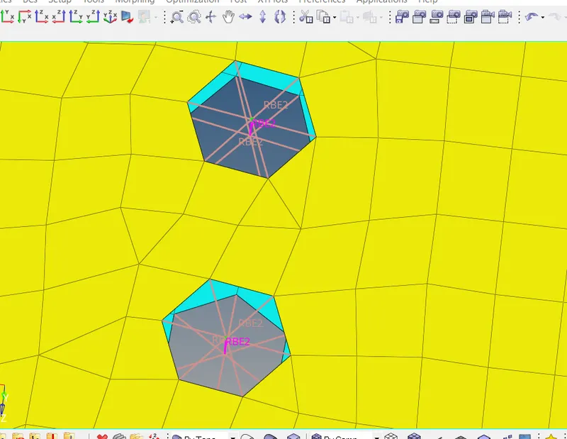
above fig. is bolt connector are created on the Rear_truss_2 & Right_Rail_2.
6. Rear_truss_2 & Left_Rail_2 bolt connectors:
- similar procedure for this component as explain in the above in bolt connnectors.
- but in this component selected type bolt is bolt(CBAR).
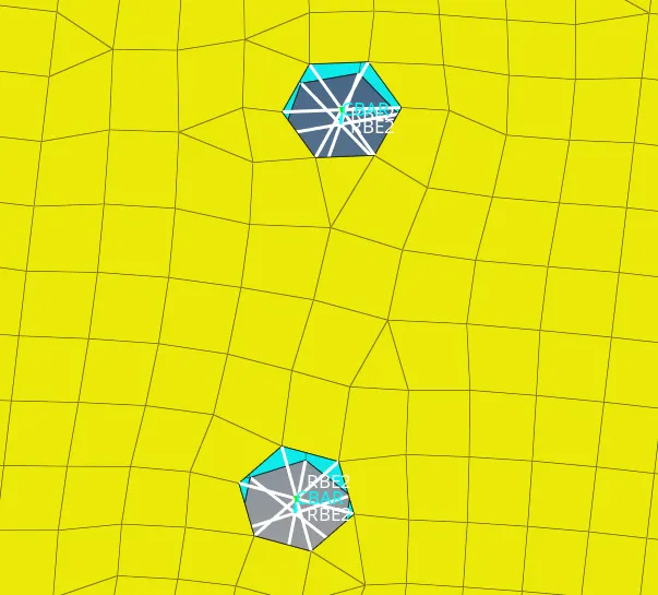
above fig bolt connector are created on Rear_truss_2 & Left_Rail.
7. Spot-weld with Rigid Elements on the Right_Rail_1 & Right_Rail_2 :
- isolate the Right Rail 1 & Right Rail 2.
- select the 1d panel from that select the spot weld.
- now select the independent and dependent nodes.
- then select the type of 1D elemnt that is rigids and search tolerence is 10.
- now select the creare option .

above fig is toolpath way.
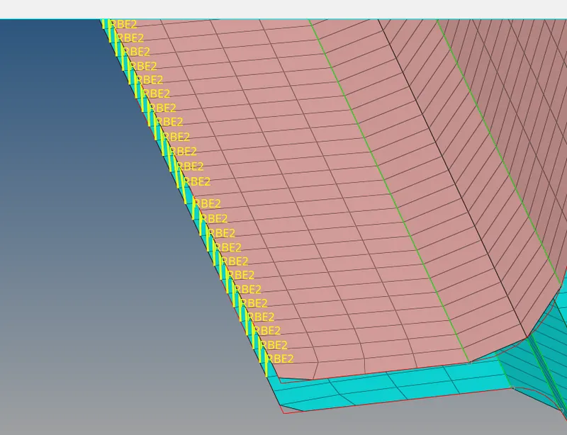
above fig rigids element are created on the Right_Rail_1 & Right_Rail_2.
8.Spot-weld with Spring Elements on the Left Rail 1 & Left Rail 2.
- similar procedure for this component where done the above for rigids .
- in this component selected 1D element is spring.
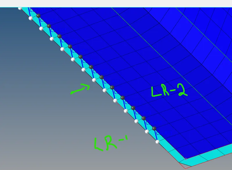
similaraly done for left component and joined with them.
learning outcomes: learned about the connectors like bolt,weld,adhesive etc... and learned how to connect with component or join them with component.
conclusion: completed the mesh for the given components and created the connectors with respective of the component in the given model.
Thank you