Week 9-Creation of 1D Connectors Challenge
REPORT
Objective:
To create mesh on the given model and join the components with suitable connectors as mentioned
CAD Model Images:
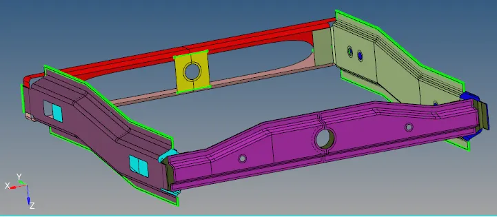
Procedure:
A) Right_Rail_2 & Front_truss_1:- Seam-Quad(angled+capped+L) weld
- The components were first imported into the Hyperworks software.
- We begin by cleaning the components. After the cleanup, the model was ready for the 2D mesh.
- The 2D mesh parameters were set such as target element size etc. and the model meshed. Then, the 2D mesh was generated.
- after that for generated seam-quad, 2D>connectors>seam>location(nodelist)>spacing(5)>comp(selected)>type(seam-quad(angled+capped+L))>create
- If the connectors are realized, then they will be in green color. If the connectors are not realized, they will be in yellow color (unrealized). If the connector fails, it is displayed in red color.
- Thus, the failed connectors are rectified by going into View>Browsers>Hypermesh>Connectors. The failed connectors are realized thereafter.
- After the weld, if the mesh in the weld region is distorted, then it is re-meshed to ensure the proper flow of the mesh.
- These procedures are followed for all the mentioned connectors below.
- Thus, the connector was generated between the two components.
Components after seam- quad weld connection
B) Left_Rail_2 & Front_truss_1:- Quad elements weld
1. 2D>connectors>seam>location(nodelist)>spacing(5)>comp(selected)>type(quad)>create
2. Thus, the connector was generated between the two components.
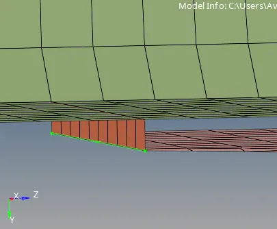
Components after quad connection
C) . Front_truss_2, Front_truss_1 & Right_Rail_1:- Spot weld with 2 Layers & 5 mm Dia
1. 2D>connectors>spot>location(nodelist)>spacing(5)>comp(selected)>num layers(total 3)>diameter(5) type(plot)>create
2. Thus, the connector was generated between the two components.
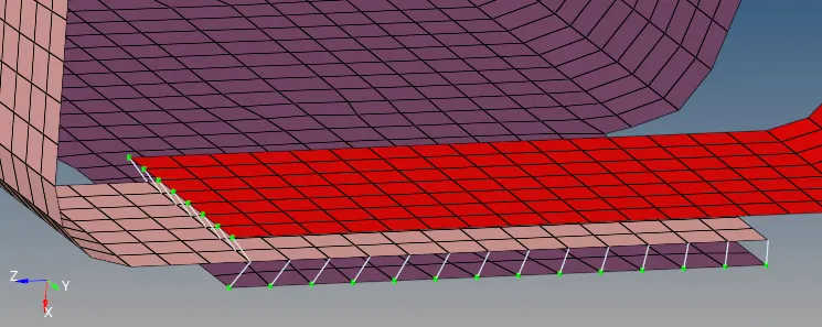
Components after spot weld
D) Front_truss_2, Front_truss_1 & Left_Rail_1:- Hexa (Adhesive)
1. 2D>connectors>seam>location(nodelist)>spacing(5)>comp(selected)>tolerance(10)>diameter(5) type(hexa(adhesive))>create.
2. Thus, the connector was generated between the two components.
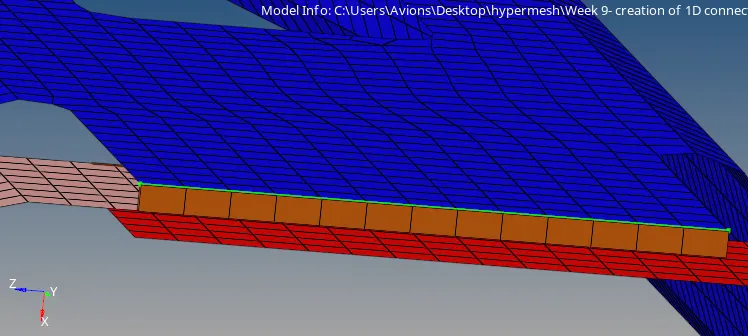
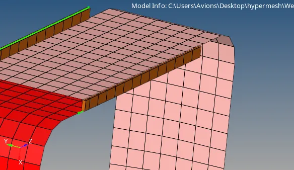
Components after seam (hexa (adhesive))
E) Rear_truss_2 & Right_Rail_2:- Bolt Connector
F) Rear_truss_2 & Left_Rail_2:- Bolt Connector
1. 2D>connectors>bolt>location(nodelist)>num layers(total 2)>comp(selected)>type (bolt(general))>create.
2. Thus, the connector was generated between the two components.
Components after bolt connection
G) Right_Rail_1 & Right_Rail_2:- Spot-weld with Rigid Elements
1. 2D>connectors>spot>location(nodelist)>comp(selected)> type(rigid)>create
2. 2. Thus, the connector was generated between the two components.
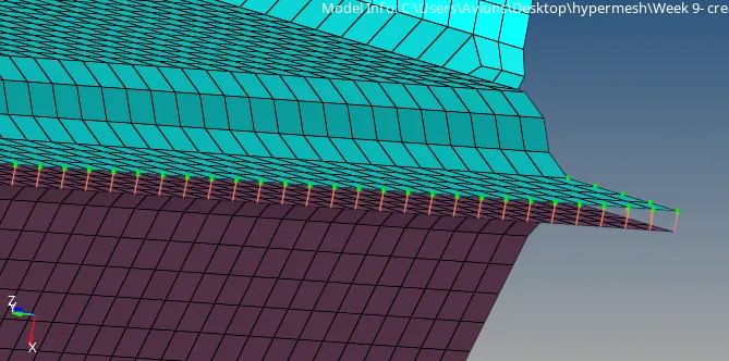
Components after spot weld with rigid elements
H) Left_Rail_1 & Left_Rail_2:- Spot-weld with Spring Elements
1. 2D>connectors>spot>location(nodelist)>comp(selected)> type(spring)>create
2. Thus, the connector was generated between the two components.
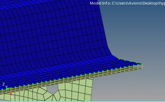
Components after spot weld with spring elements
I) Reinf_Plate, Front_truss_1 and Front _Truss_2
1. The reinforcement plate is connected with the front truss 1 and front truss 2 with the help of seam-quad( angled+capped +L) weld.
2. 2D>connectors>seam>location(nodelist)>spacing(5)>comp(selected)>type(seam-quad(angled+capped+L))>create
3. Thus, the connector was generated between the two components.
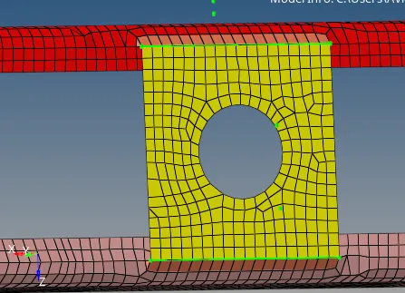
Components after seam quad weld