Week 4-1D Element Creation Challenge
REPORT
Objective:
1. To mesh the model with the given element size of 5units.
2. To create 1D elements on the component with the given cross-section and degree of freedom.
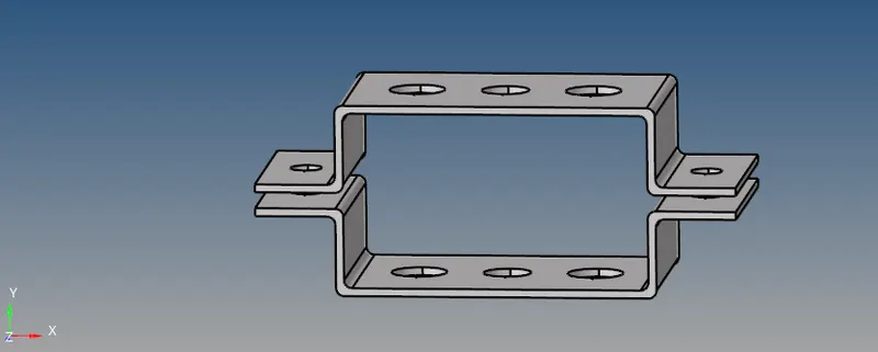
CAD Model Image:
Procedure:
- The model (bracket) was imported into the Hyperworks software.
- We begin by creating the mid surface of the model. Initially, we create a mid surface of the upper body of the bracket by changing the extraction options of the mid surface command. Starting with the "offset+planes+sweep" command, mid surfacing was performed but it was unable to capture the fillet edges. After that, the "offset+plane" command was used as the extraction option but was also unable to capture the mid surface properly as it had undesirable features and was not deployed. After tweaking the "skin offset" option, all the surfaces along with the edged fillets were obtained properly.
- After the mid surface is created, the mid surface is a 2D representation of the 3D model, we assigned material as steel to it in order to give a thickness. Then the Card image of "MAT1' was selected based on the solver and the properties were populated. Then the two different properties were created and were assigned to two components (upper and lower bodies of the bracket). PSHELL elements were chosen as it was mid surfacing.
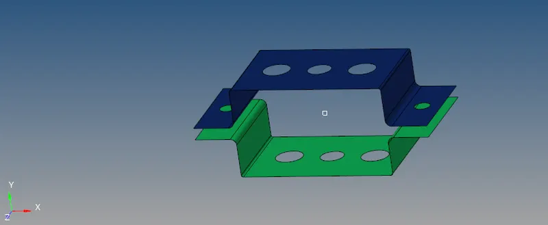
Component after Mid-Surfacing
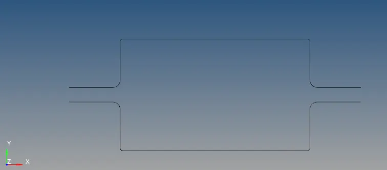
Component after Mid-Surfacing (Front View)
3. After this step, washer-splits were created near the holes to enhance the mesh quality near holes and to improve mesh efficiency and results. The mesh was created on the mid surfaces using the element size of 5 units. Initially, the mesh did not capture the fillet edges properly and the washer-splits as well, therefore, the number of nodes at these critical regions was increased until the curvature was captured properly.
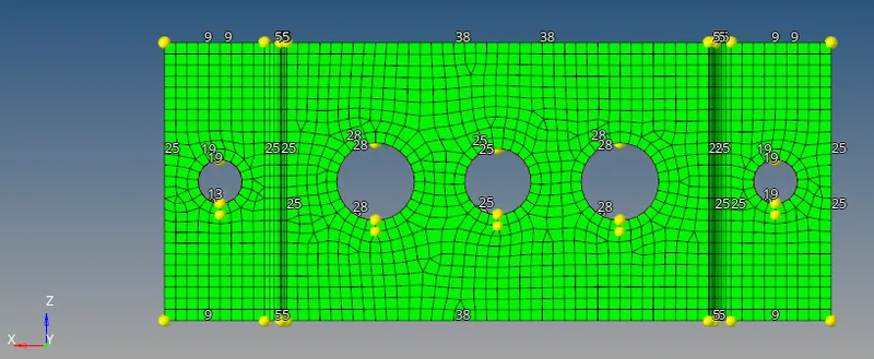
Mesh Generation
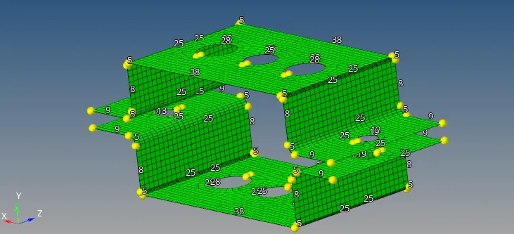
Mesh generation
4. Once the mesh was generated, RBE2 links were created. This was done by choosing the "Rigids>selecting nodes by the path and selecting multiple nodes>create". Translational DOFs were constrained according to the question. Similar steps were followed for the other connecting RBE2 link as well.
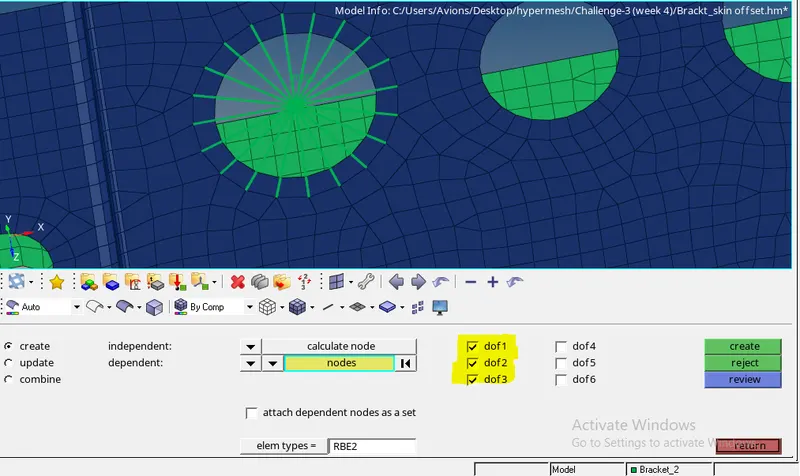
RBE2 Link creation
5. RBE3 links were also created. This was done by choosing the "rbe3>selecting nodes by the path and selecting multiple nodes>create". All DOFs were constrained according to the question. Similar steps were followed for the other connecting RBE3 link as well.
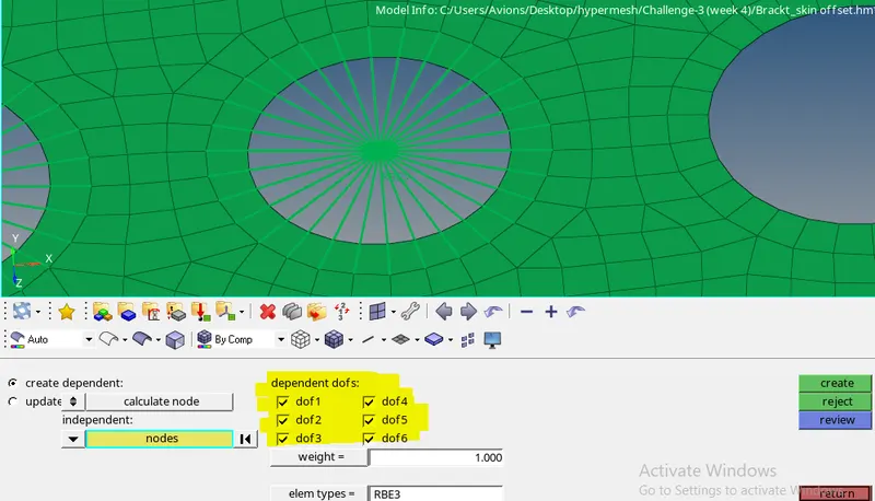
RBE3 Link creation
6. Similarly, RBE3 links were again created. This was done by choosing the "rbe3>selecting nodes by the path and selecting multiple nodes>create". Only x and y DOFs were constrained according to the question. Similar steps were followed for the other connecting RBE3 link as well.
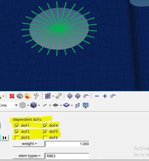
RBE3 Link creation
7. 1D element Creation:
a) ROD Element
The ROD element was created by selecting the following commands "rods>nodes selection>CROD>create".
Once the element was created, it was crucial to assign the cross-section to the element. It was done by "1D>HyperBeam>standard section>create". Then the Hyperbeam windows opened and according to the question, a box of necessary dimensions was created. This was done by "create>standard section>Hypermesh>const.perimeter box". Then the properties of the ROD element had to be given > therefore, the property was created with"create>property>Card image=PROD>Beam section=rod box". Similar steps were applied for CBEAM and CBAR elements creation as well.
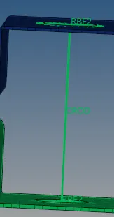
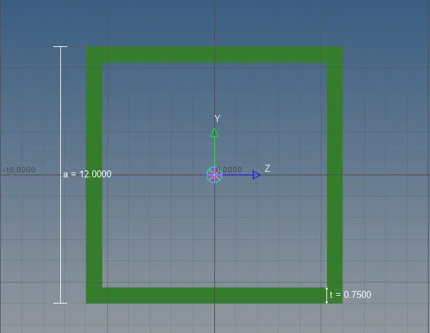
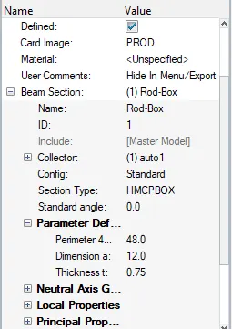
CROD element Cross Section of CROD Element Properties of Cross Section
b) BEAM Element
The BEAM element was created by selecting the following commands "bars>nodes selection>element type=CBEAM>orientation=nodes selection along axis>create".
Once the element was created, it was crucial to assign the cross-section to the element. It was done by "1D>HyperBeam>standard section>create". Then the Hyperbeam windows opened and according to the question, an I-section of necessary dimensions was created. This was done by "create>standard section>Hypermesh>I section". Then the properties of the Beam element had to be given > therefore, the property was created with"create>property>Card image=PBEAM>Beam section=I-section".
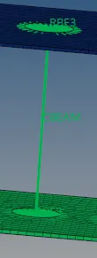
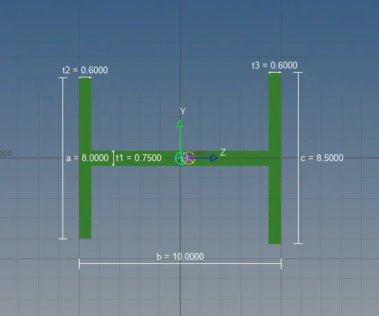
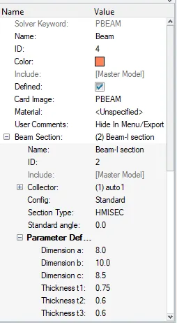
CBEAM element Cross Section of CBEAM Element Properties of Cross Section
c) BAR Element
The BAR element was created by selecting the following commands "bars>nodes selection>element type=CBAR>orientation=nodes selection along axis>create".
Once the element was created, it was crucial to assign the cross-section to the element. It was done by "1D>HyperBeam>standard section>create". Then the Hyperbeam windows opened and according to the question, an X-section of necessary dimensions was created. This was done by "create>standard section>Optistruct>Cross". Then the properties of the Beam element had to be given, therefore, the property was created with"create>property>Card image=PBAR>Beam section=X-sec".
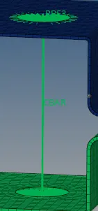
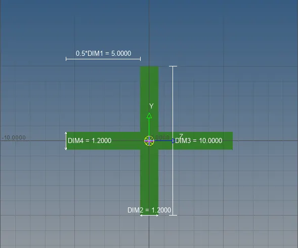
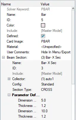
CBAR element Cross Section of CBAR Element Properties of Cross Section
d&e) Once the mesh was generated, RBE2 links were created. This was done by choosing the "Rigids>selecting nodes by the path and selecting multiple nodes>create". The center node of the link was selected and a mass of 10 was applied. This was done by "1D>mass>node selection>mass=10>element type=CMASS1". Similar steps were applied for the other hole as well at 'e'.
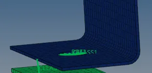
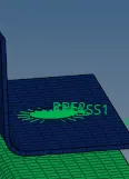
Mass of 10 at 'd' with RBE2 link Mass of 10 at 'e' with RBE2 link
f) Joining the two components by Spring elements
The Two components were joined by spring elements marked as 'f'. The spring elements were generated by 1D>selection of nodes>dof1>element type=CELAS1.
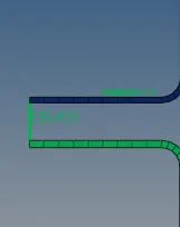
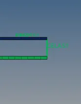
Two Components joined by Spring Elements 'CELAS1'
Results and Final Model Image:
After taking into account all these steps, the final model was generated and is shown below:
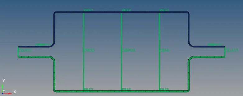
1D Traditional element Representation
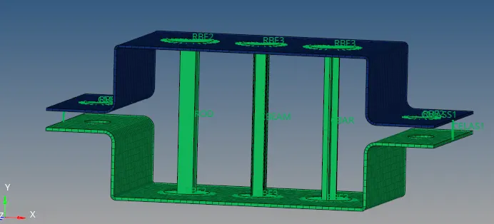
1D Detailed element Representation
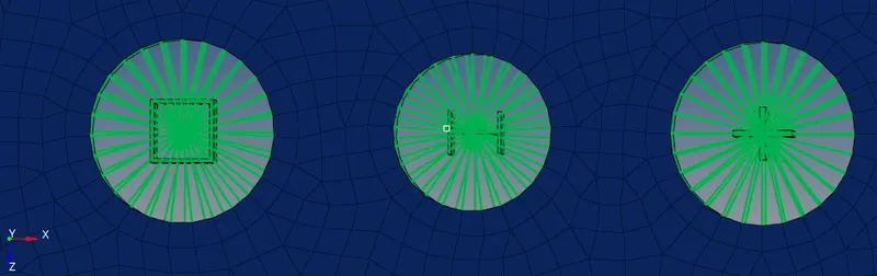
1D detailed cross-sections BOX,I-sec and X-sec for ROD, BEAM, and Bar element respectively (left to right)
While carrying out the 2D Detailed representation, it can be seen that the filleted edges have not been compromised at all and the mesh has captured it properly. This was of main concern because it depends on the type of mid surfacing options chosen at the time of mid surfacing. Several extraction options were changed and the best one was chosen which captures the geometry perfectly.
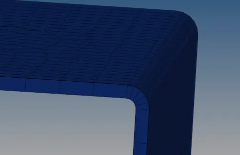
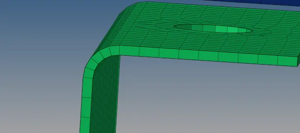
2D Detailed representation of Fillet edges