Week 12:Project 2-Meshing of Rear Wheel Holder challenge
REPORT
Objective:
To clean the model, and mesh, follow all quality criteria and assign thickness
CAD Model Images:
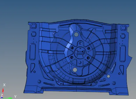
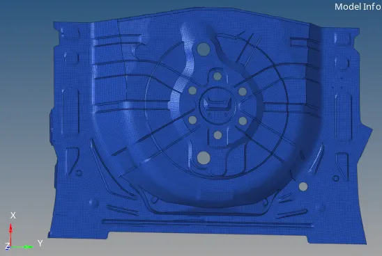
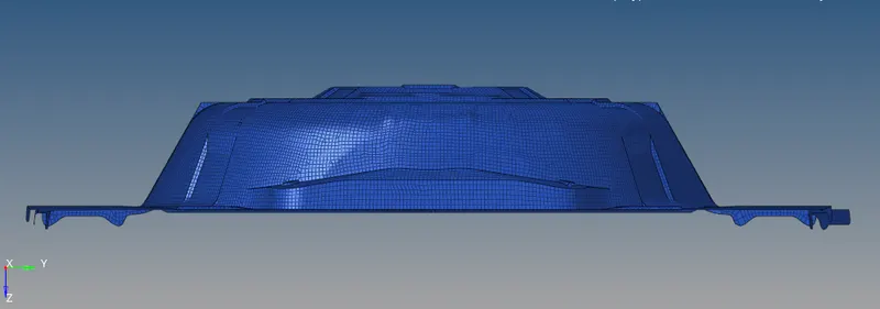
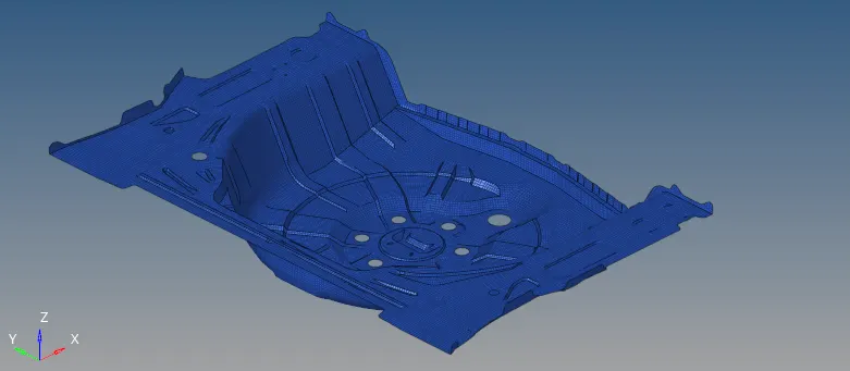
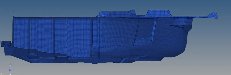
Rear-wheel Holder (Model)
Procedure with Required Images:
1. The FE models were first imported into the Hyperworks software.
2. We begin by cleaning the models. The surfaces were cleaned of any irregularities such as buttons etc.
3. Once the model is cleaned, we begin to generate the mid-surface of the model. It can be done both manually and in auto mode. The model is mid-surface using auto mode which captured the mid-surface quite well.
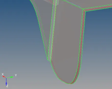
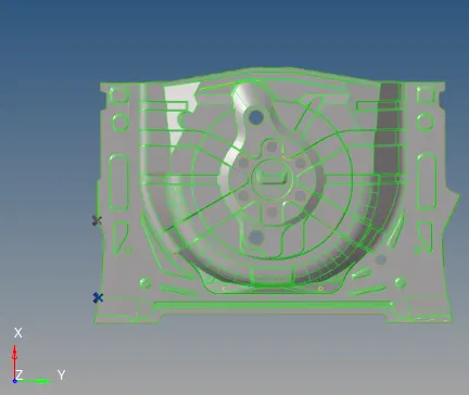
Mid-Surfacing
4. After the mid-surface is generated, it is also cleaned up and checked for errors under the topology mode. Errors such as surface overlapping can occur which were rectified.
5. Some edges which were not stitched were toggled using the quick edit option. F11>toggle.
6. Some surfaces which were missing were also filled using the filler surf option to maintain a good curvature throughout, F11>toggle edge. Some points which were unnecessary were replaced using the replace point option under the quick edit panel.
7. Excess points in the model causes extra nodes in the model after meshing which unnecessarily increase the nodes. Therefore, the number of points was minimized by removing or replacing them.
8. Now, we move on to meshing the model. there are various methods to mesh the model, but we chose the batch meshing option. The reason is the time taken to mesh the model manually. Initially, started with manually meshing, taking each surface into account, and then meshing. Many options such as "split-surf nodes" were used to split the surface through nodes in order to maintain a good mesh flow. But it consumed a lot of time and hence has not been opted.
9. We procced through the batch meshing option. The reason for selecting batch-meshing is faster meshing and the elements can be rectified later based on the quality criteria. Therefore, the parameter file was chosen based on the max. length(8mm) and the min. length (2mm) which was in the range of the Target element length(5mm).
10. The parameter file of "durability_5mm. param " was chosen as a parameter file and the same followed for the criteria file as well.
11. Once, the meshing was done, we begin to check the elements for quality and mesh flow.
12. The surface was observed and the concentrated tria elements were removed. We begin by meshing the elements again and removing all trias possible. F12>elem>size:5>type: mixed>mesh.
13. Removing trias entirely is not necessary until and unless they are on edges, features, or fillets.
14. Therefore, most of the trias were removed which were there and the tria elements were minimized as much as possible. According to the question, the percentage of tria elements was kept below 10 %.
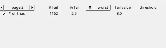
Trias Percentage
15. To ensure proper mesh flow, The elements were smoothened using the smooth command, shift+F12>elem>smooth. The mesh connectivity is also a very important factor, which ensures that the load gets distributed smoothly when applied.
16. To achieve this, the nodes which were not connected together were connected by using the replace node command, F3>replace(node)>with(node)>replace, and the nodes were connected together.
17. After the mesh is generated, the required thickness is assigned. The thickness value is taken by taking the average thickness of the entire model. Since the model had variable thickness along with its geometry, an average value was taken and was assigned.
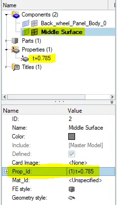
Thickness property
18. To assign the thickness, we first need to create the property. Create>Property. Property>Thickness(value).
19. Now, we go to the middle surface collector>click> Prop-id>select prop. To view the applied thickness, we enable the '2D detailed element representation' option.
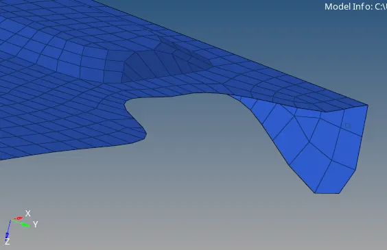
Without thickness
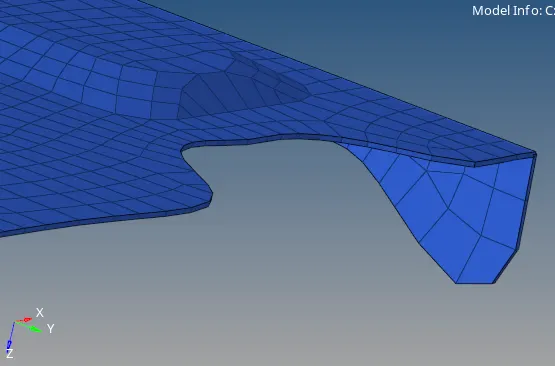
Thickness applied to model
Results and final model Image:-