Week 6-Meshing of Hood Challenge
REPORT
Objective:
1. Generating Midsurface and geometry clean up on the given component
2. Generating mesh on the given component with low tria concentration and proper mesh flow
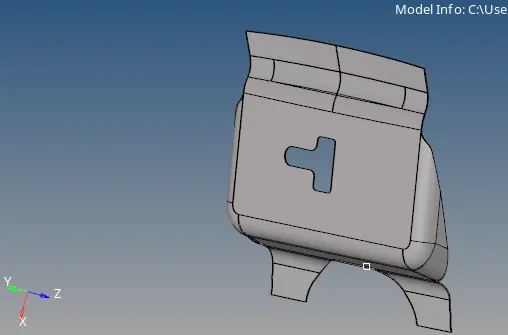
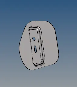
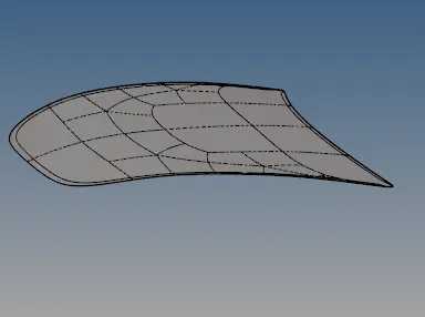
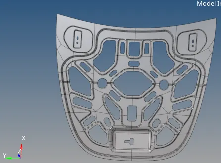
CAD Model Image:
Procedure:
- The model was first viewed of any irregularities or any issues it might have. We begin by first identifying them. This is done "Geometry color mode>By Topo".
- This option visually populates all the areas which have issues and need cleanup. As far as the model is concerned, it had many missing surfaces which needed to be filled and thus the necessary operations were performed.
- As each component was to be taken separately, we begin by performing operations of individual components.
- First, The Latch component of the hood was mid-surfaced. After mid-surfacing was done, it was cleaned up using the auto clean up command. It populates and all the necessary edges were suppressed and modified accordingly.
- Then the mid surface was meshed using the mixed meshed option and a target element size of 5mm. Then elements were checked and all the parameters such as warpage, max. length etc were satisfied. for this, the elements were quality checked 'using the 2D>quality check'. All the elements were checked and rectified. Since the primary goal was also to check for trias and minimize the number of trias, they were dragged out using the 'drag trias ' option.
- The mesh was also checked for proper flow and the elements were repeatedly enhanced to achieve that. The nodes which were not aligned were aligned using '1D>node edit>align'.
- Then the entire region was smoothened using the smooth command to enhance mesh flow.'2D>smooth>elements'
- Similar operations were performed for other respective components as well.
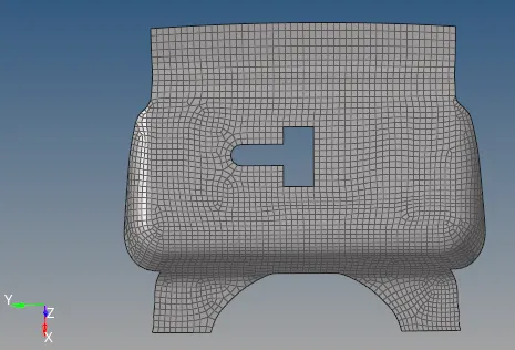
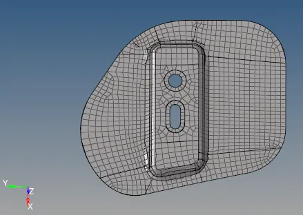
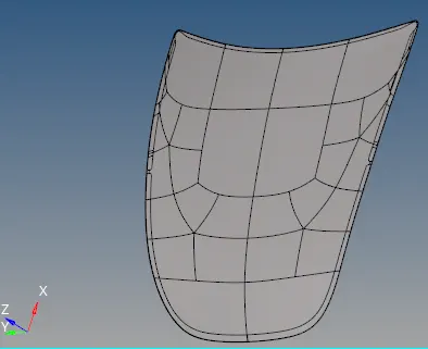
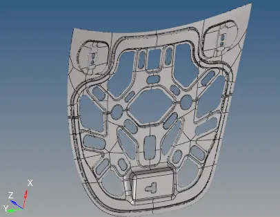
The meshed surfaces of each component
9. After the meshing was completed , the mesh was optimisd using'2D>quality index'. All the components which were failed were optimised respectively. Most of the elements which still cannot be optimised are only due to max and min length criteria.But, majority of the elemnts satisfied the mesh conditions and a proper mesh flow was generated .
Results and final image model:
Pictures below shown are the final mesh generation on the components. Care has been taken to maintain a smooth mesh flow and reduction of tria elements as much as possible.
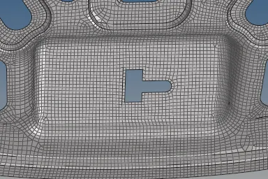
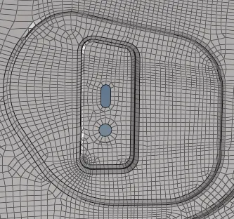
Final mesh of Latch Final mesh of Hinge
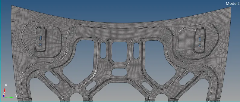
Final mesh on top section of the inner part
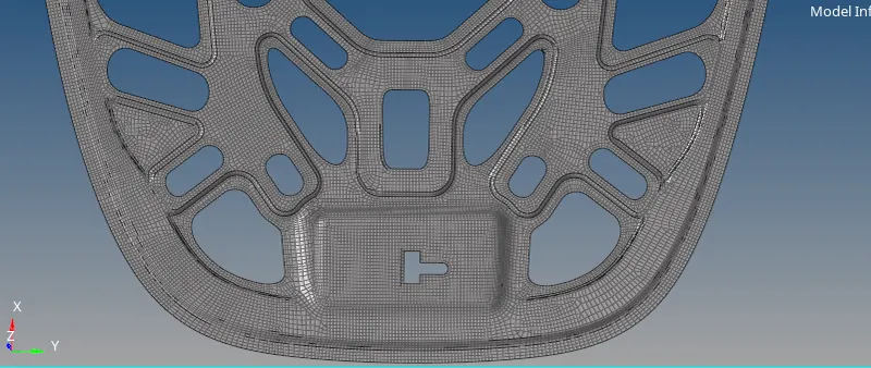
Final mesh on bottom section of the inner part