Week 9-Creation of 1D Connectors Challenge
AIM: To create mesh and assign connectors between various components on given models by using hypermesh.
OBJECTIVE
- To perform geometry cleanup and discretize the components using shell mesh.
- To create a connection between Right Rail 2 & Front truss 1 by using Seam-Quad (angled+ capped+ L) elements.
- To create a connection between Left Rail 2 & Front truss 1 by using Quad elements.
- To create a connection between Front truss 2, Front truss 1 & Right Rail 1 by using Spot weld with 2 Layers and 5 mm Diameter.
- To create a connection between Front truss 2, Front truss 1 & Left Rail 1 by using Hexa (Adhesive).
- To create a connection between Rear truss 2 & Right Rail 2 by using Bolt Connector.
- To create a connection between Rear truss 2 & Left Rail 2 by using Bolt Connector.
- To create a connection between Right Rail 1 & Right Rail 2 by using Spot-weld with Rigid Elements.
- To create a connection between Left Rail 1 & Left Rail 2 by using Spot-weld with Spring Elements.
- Rest all the component left Join them with suitable connectors.
PROCEDURE:
1. CAD MODEL:
Open the hyperwork software, and then we have to set user profile interface i.e. Optistruct or RADIOSS. Optistruct is implicit solver which handles small deformations. And RADIOSS is explicit solver which handles large deformation. So we will use Optistruct as user interface.
First we have to import the required file i.e. frame_assembly_welding, which is in .hm format. So to import the .hm file format model in hyperworks, we have to follow: File--->Import---->Model----> select file--->Import. Once model is opened, then we will switch the geometry color mode from “auto mode” to “By Topo”. Once mode is changed model will look like as shown in picture below.
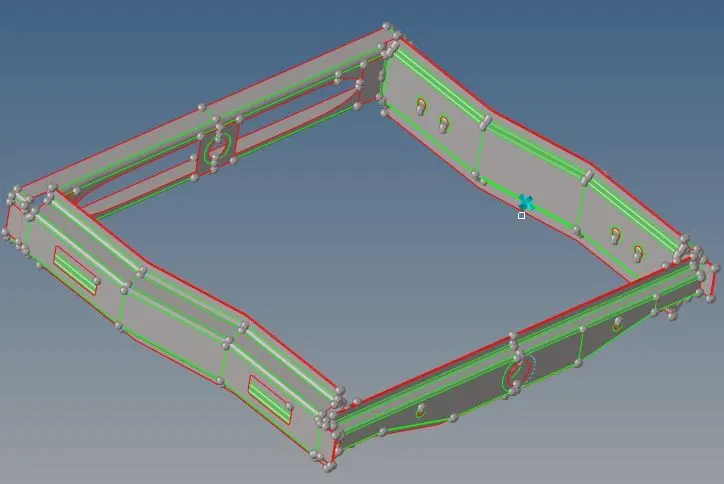
Figure 1: CAD model of frame assembly welding
Frame assembly model consist of following components as shown in picture below:
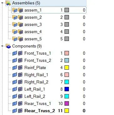
Figure 2: Components of frame assembly welding
2. Geometry cleanup:
To perform geometry cleanup operation, we will use autocleanup panel. Cleanup operations include the equivalencing of "red" free edges, fixing of small surfaces (relative to the element size), and detection of features such as beads. It also performs specified surface editing/defeaturing operations like the removal of pinholes (less than specified size), removal of edge fillets, and the addition of a layer of washer elements around holes.
To perform this operation, we have to follow:
Geometry---->autocleanup---->select surface: all---->autocleanup
In order to resolve those errors which are not auto detected, we have to manually perform spline / filler, ruled options to repair geometrical errors by following Geom---->Surfaces---->select spline/filler or ruled.
Spline/filler subpanel option helps to create surfaces by filling in gaps, such as a hole in existing surface. And ruled subpanel option helps to create surfaces by interpolating linearly between lines or nodes.
Once geometrical errors are resolved model will look like as shown in picture below.
As we will perform defeaturing, which will help us to provide good meshing flow by eliminating unnecessary CONS on flat surfaces. To suppress these unnecessary CONS we have to perform toggle function by following
Geom---->edge edit---->toggle.
So, same procedure will required for all the components of the given model as per requirement.
3. Quality criteria parameters
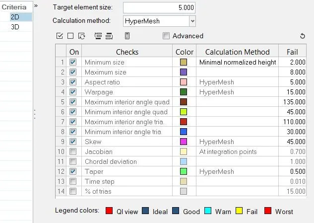
Figure 3: Quality criteria parameters
4. Discretization of component:
4.1 2D Shell elements:
A mesh is a network that is formed of cells and points. A meshing is the process of subdividing the structure from infinite number of points to the finite number of node and elements. This process is also known as discretization.
And we have to maintain the distance between two nodes equal to the average target length i.e. 5mm. This can be done by following certain steps i.e.
2D---->automesh---->select surface---->element size---->mesh type: Trias---->mesh.
In order to fix quality meshing we will use some of useful function such as remesh, rebuild mesh, smooth, split elements, align nodes, replace nodes etc.
We will also use normal panel which is under tool. Normal panels help to display and reverse the normal of elements or surfaces.
Once discretization is done, we need to verify the connectivity between the nodes throughout. To verify and correct connectivity we will use equivalence by following certain steps.
Tool---->edges---->select element---->preview equivalence---->equivalence
we can also increase the tolerance value if the nodes are not getting highlighted. Once meshing is done, model will look like as shown in picture below.
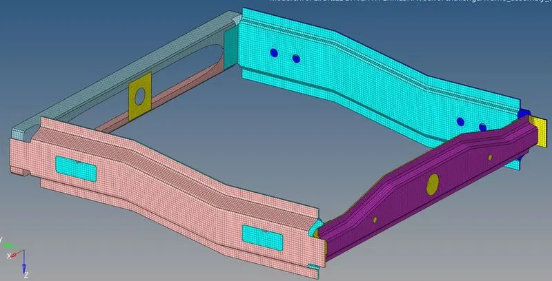
Figure 4: Discretization of frame assembly welding
4.2 Element quality checking
During meshing we have to take care of element quality. Element quality help us to understand how much the element has deviated from the ideal element. Because during meshing poor elements will misrepresent the geometry and will lead to inappropriate results. To perform quality check operation, we have to follow certain steps i.e.
2D---->quality index
In quality index we have cleanup tools which helps us to fix element quality such as drag tria elements, element optimize, split quad element and combine tria element etc.
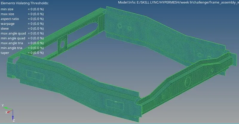
Figure 5: Element quality checking of frame assembly welding
5. To create connectors
Connectors are geometric entities, which are primarily used to represent the CAD geometric connections in terms of FEA. Connection can be created as a spot-weld, seam-weld, adhesive, bolts and masses. A realized connector will be considered as successful representation of a CAD model in preprocessing and connecting parts considered as connected.
5.1 To create a connection between Right Rail 2 & Front truss 1 by using Seam-Quad (angled+ capped+ L)
Seam weld is the process of joining the workpiece which are made of similar or dissimilar material along a continuous seam is known as seam weld.
To create Seam-Quad (angled+ capped+ L) connection, we have to follow:
1D---->Connectors---->Seam option.
And then we have to follow steps as shown in picture below in order to establish connection.

Figure 6: Seam-Quad (angled+ capped+ L) connection
Once connection is established, model will look like as shown in picture below.
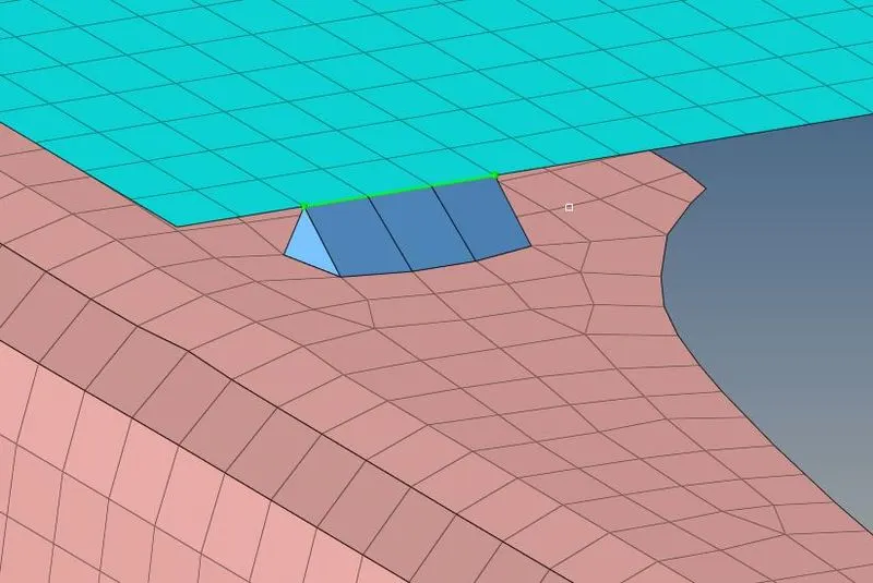
Figure 7: Seam-Quad (angled+ capped+ L) connection
5.2 To create a connection between Left Rail 2 & Front truss 1 by using Quad elements.
To create Seam-Quad connection, we have to follow:
1D---->Connectors---->Seam option.
And then we have to follow steps as shown in picture below in order to establish connection.

Figure 8: Quad elements connection
Once connection is established, model will look like as shown in picture below.
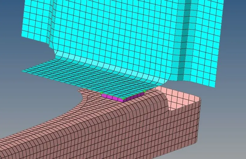
Figure 9: Quad elements connection
5.3 To create a connection between Front truss 2, Front truss 1 & Right Rail 1 by using Spot weld with 2 Layers and 5 mm Diameter.
Spot welding is a resistance welding process that is used primarily for welding two or more metal sheets together by applying pressure and heat to the weld area.
Heat for the welding process will be obtained from resistance to electric current. Realized spot weld in Hypermesh will represent the connection between the components.
To create a spot weld connection, we have to follow
1D---->Connectors---->Spot option.
And then we have to follow steps as shown in picture below in order to establish connection.

Figure 10: Spot weld with 2 Layers and 5 mm Diameter connection
Once connection is established, model will look like as shown in picture below.
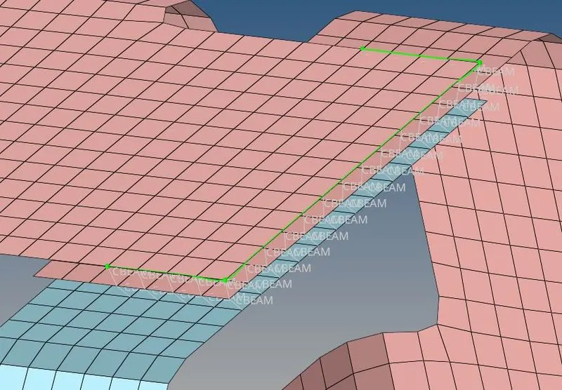
Figure 11: Spot weld with 2 Layers and 5 mm Diameter connection
5.4 To create a connection between Front truss 2, Front truss 1 & Left Rail 1 by using Hexa (Adhesive).
To create Hexa (Adhesive) connection, we have to follow:
1D---->Connectors---->Seam option.
And then we have to follow steps as shown in picture below in order to establish this connection

Figure 12: Hexa (Adhesive) connection
Once connection is established, model will look like as shown in picture below.
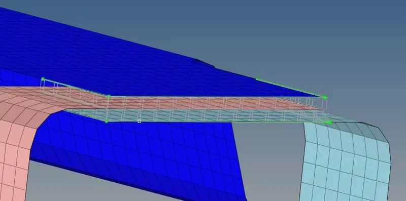
Figure 13: Hexa (Adhesive) connection
5.5 To create a connection between Rear truss 2 & Right Rail 2 by using Bolt Connector.
Bolt joints are one of the most common elements in construction and machine design. A connection between structural members made with plates and bolts, as opposed to riveted or weld connection. In hypermesh, we use the RBE2 elements to represent the bolt connection
To create bolt connection, we have to follow:
1D---->Connectors---->bolt option.
And then we have to follow steps as shown in picture below in order to establish this connection.

Figure 14: Bolt connection
Once connection is established, model will look like as shown in picture below.
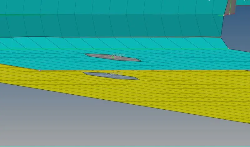
Figure 15: Bolt connection
Now if we need to change the bolt type. Then we need to realize the connector by following steps as explained in picture below.

Figure 16: Bolt connection
Once connection is established, model will look like as shown in picture below.
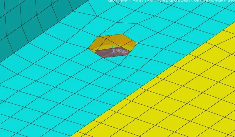
Figure 17: Bolt connection
5.6 To create a connection between Rear truss 2 & Left Rail 2 by using Bolt Connector.
To create bolt connection, we have to follow:
1D---->Connectors---->bolt option.
And then we have to follow steps as explained in earlier case. Once connection is established, it will look like as shown in picture below.
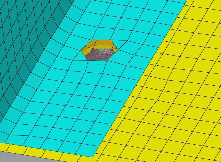
Figure 18: Bolt connection
5.7 To create a connection between Right Rail 1 & Right Rail 2 by using Spot-weld with Rigid Elements.
To create a spot weld connection, we have to follow
1D---->Connectors---->Spot option.
And then we have to follow steps as shown in picture below in order to establish connection.

Figure 19: Spot-weld with Rigid Elements connection
Once connection is established, model will look like as shown in picture below.
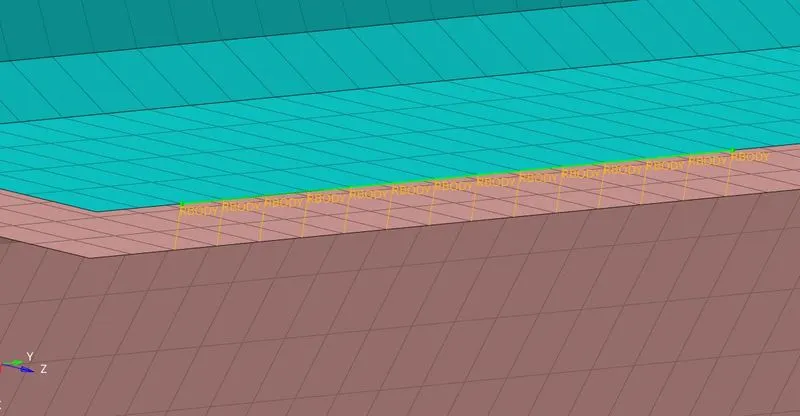
Figure 20: Spot-weld with Rigid Elements connection
5.8 To create a connection between Left Rail 1 & Left Rail 2 by using Spot-weld with Spring Elements.
To create a spot weld connection, we have to follow
1D---->Connectors---->Spot option.
And then we have to follow steps as shown in picture below in order to establish connection.

Figure 21: Spot-weld with Spring Elements connection
Once connection is established, model will look like as shown in picture below.
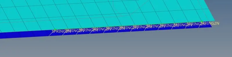
Figure 22: Spot-weld with Spring Elements connection
5.9 To create connections for Rest of all the.
5.9.1 Connection between reinforcement plate and Front truss 1 & 2
Now we have to create seam-quad connection, we have to follow:
1D---->Connectors---->Seam option.
Once connection is established, model will look like as shown in picture below.
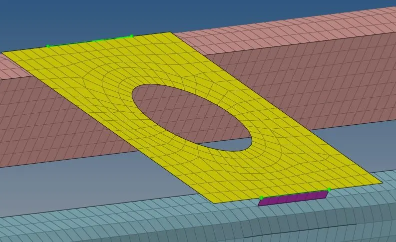
Figure 23: Quad elements connection
5.9.2 Connection between Rear truss 1 and Rear truss 2
To create a spot weld connection with rigid elements, we have to follow
1D---->Connectors---->Spot option.
Once connection is established, model will look like as shown in picture below.
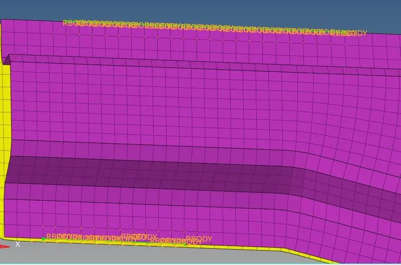
Figure 24: spot weld connection with rigid elements
Result and Conclusion
So, 2D shell elements with Connections are created and realized Successfully.
Finally, the entire connections with meshed components are shown below.
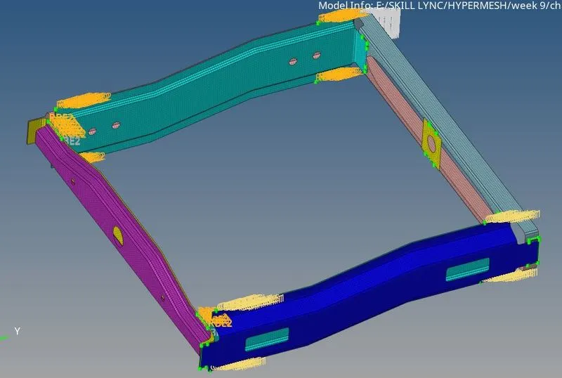
Figure 25: CAD model of frame assembly welding