MESHING COMPARISON OF A SHEET METAL COMPONENT USING MANUAL, BATCH AND CASTING METHOD IN ANSA
AIM: To perform a mid surface extraction and meshing by using skin, casting and then batch meshing method by using ANSA.
OBJECTIVE:
- Geometry cleanup of a sheet metal component.
- Middle surface extraction using manual, skin face auto generation.
- Assigning quality presentation parameters and mesh parameters.
- To perform manual and batch meshing with quality checking.
- To perform casting method with quality checking on parent geometry.
- Comparison of all three meshing results.
CAD MODEL:
First, we have to Import the required CAD file in ANSA software by using GUI option. Once model is open, model looks like as shown in picture below.
This CAD model is having uniform thickness of 1mm throughout. So, we can say this is sheet metal component.
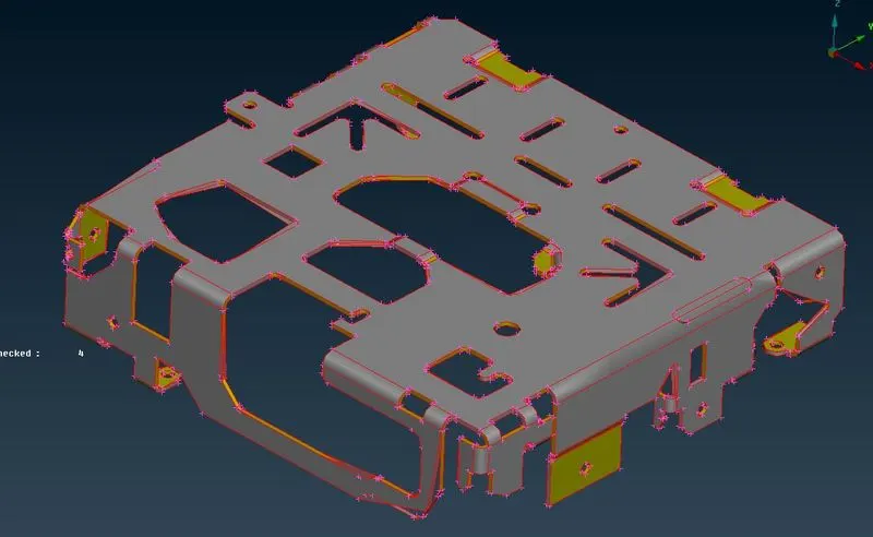
Figure 1: CAD Model
PROCEDURE:
1. Geometry cleanup:
1.1 Topology cleanup
From model we can see each macros are not connected to each other. So in order to connect it, we will perform “TOPO” function which is available under Faces. Topo function will perform by box selection of visible component. Once topo will perform model will look like as show in picture below:
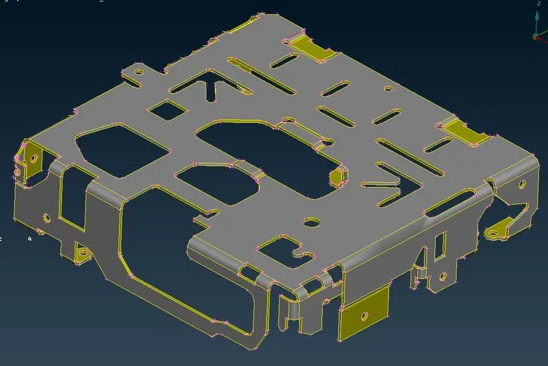
Figure 2: Topology cleanup
1.2 Geometry cleanup:
To perform geometry cleanup, ANSA is having default selection parameters template in its geometry macro. In template we will select all available options excepts sharp edges and unmeshed macros.
By selecting visible under execute on and then select execute to check the geometrical errors in the geometry.
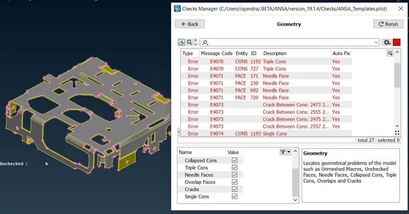
Figure 3: Geometry cleanup
In order to fix these geometrical errors, we can use either manual or auto fix option. As we can see Yes in Auto Fix check. So we will use auto fix option to solve these errors from the visible geometry. This action will help us to save time to solve errors.
In order to confirm result. we will rerun the above mentioned process for geometry checkup. Then after rerun the process found no errors as shown in picture below.
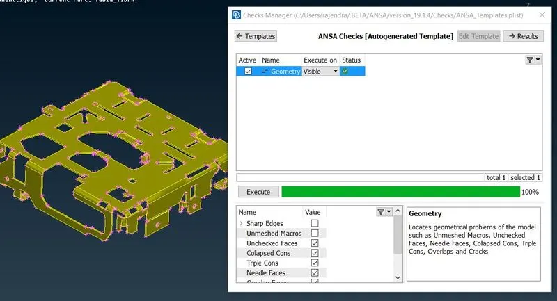
Figure 4: Geometry cleanup
2. Mesh Parameters and quality criteria
Before proceed to meshing, we have to assign different mesh parameters such as average Target length, minimum and maximum target length. And we have to keep element type is “Mixed”. According to these parameters our mesh model will get discretize.
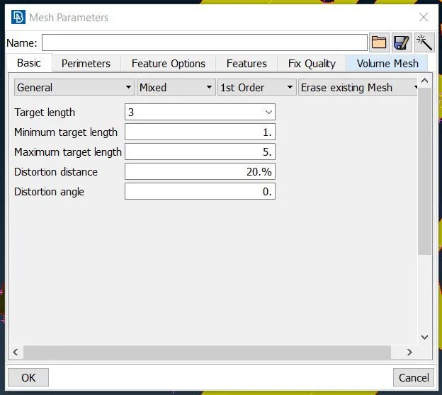
Figure 5: Mesh Parameters
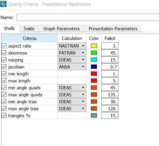
Figure 6: Quality criteria - Presentation Parameters
3. MID surface extraction and Meshing
3.1 Manual method
3.1.1 MID surface extraction by Manual Method:
Before going to middle surface extraction, we have to check orientation of faces for CAD model. In order to change orientation, we can use function TOP---->Faces---->Orient. Where, yellow color shows negative and grey color shows positive direction.
In manual method MID surface is extracted by using offset option which is available in
TOP---->Faces---->Orient.
So, we have to offset the top selected face by 0.5mm as shown in picture below.
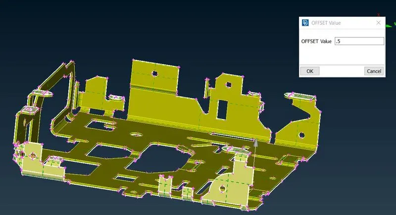
Figure 7: MID surface extraction by Manual Method
After middle mouse click middle surface get extracted automatically as shown in picture below.
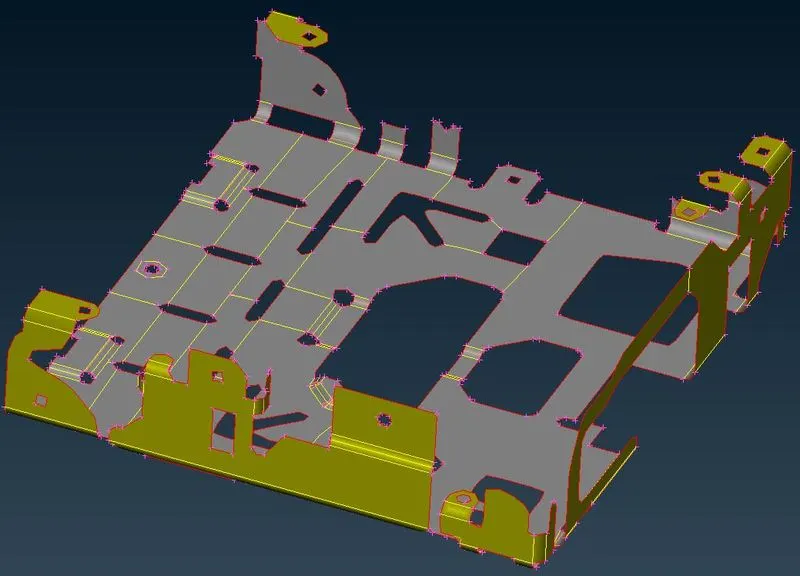
Figure 8: MID surface extraction by Manual Method
3.1.2 Discretization of component by manual method
A mesh is a network that is formed of cells and points. A meshing is the process of subdividing the structure from infinite number of points to the finite number of node and elements. This process is also known as discretization.
In ANSA, we have variety of options to perform meshing. Now, we will use “BEST” and “SPOT” option for meshing to generate FE elements on each and every surface of model.
During meshing we have to take care of quality criteria. Because on click of meshing option, it will generate improper meshing. So we have to improve meshing pattern in order to satisfy the quality criteria.
Meshing has been performed using BEST and SPOT mesh algorithm. Using Reconstruct, Fix quality function in shell mesh, we have achieved high quality surface mesh. To achieve the overall quality, reconstruct function examine the current mesh and performs re-meshing in order to optimize the overall quality of mesh.
After performing meshing, component will look like as shown in picture
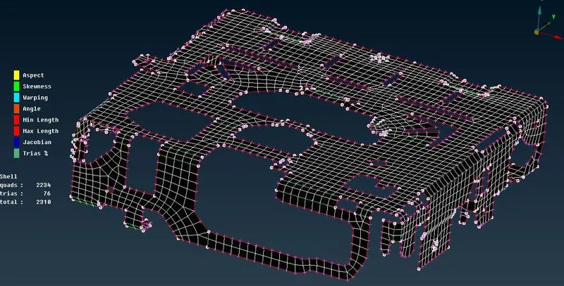
Figure 9: Discretization of component by manual method
3.2 Batch Meshing method
3.2.1 MID surface extraction by skin Method:
In this method, mid surface was extracted by using skin method. By using the mid surface command, original component is deleted and a new PID is generated as a skin as shown in picture below.
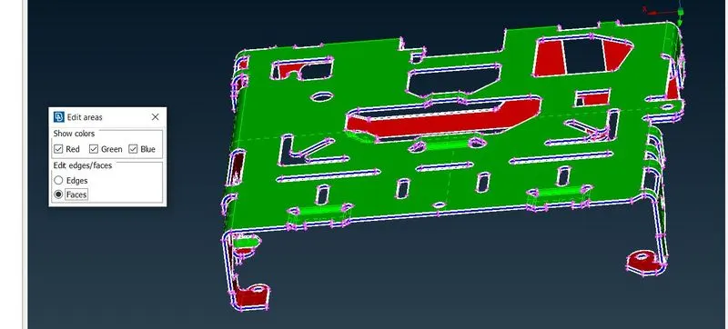
Figure 10: MID surface extraction by skin Method
Once mid surface is achieved, it will look like as shown in picture below.
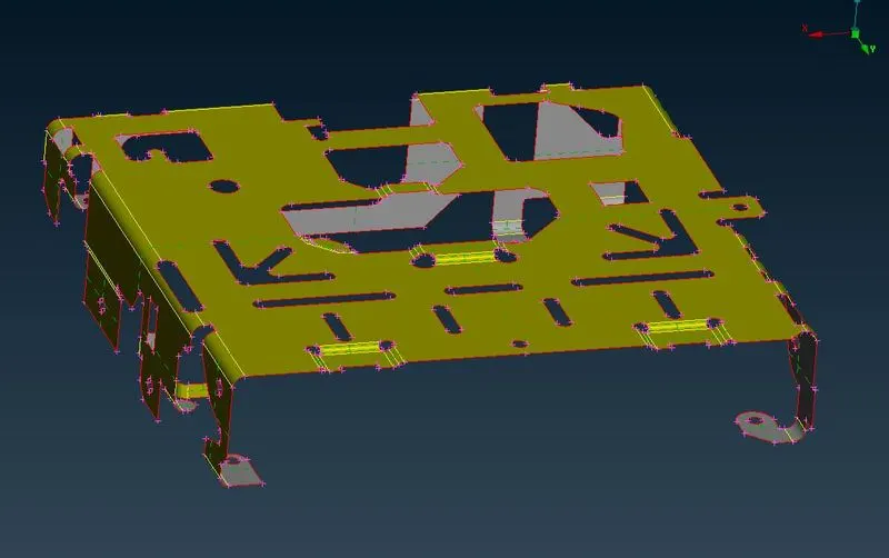
Figure 11: MID surface extraction by skin Method
3.2.2 Discretization of component by Batch Meshing method
Before starting batch meshing, we have to assign a new property identity for the generated mid surface.
First we have to open model browser (Ctrl+R) ---->New---->Part from visible---->OK
Now if we select latest created file in model browser, it will highlight mid surface part at right bottom that we have already assigned to it as shown in picture below.
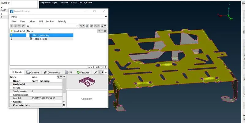
Figure 12: Discretization of component by Batch Meshing method
Then we have to open Batch mesh manager(Ctrl+B) ---->New---->Meshing Scenario.
This step should be done after assigning quality criteria parameters.
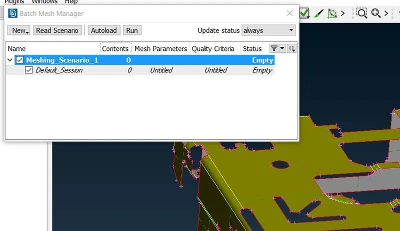
Figure 13: Discretization of component by Batch Meshing method
After double click on contents, new window will get pop up as shown in picture below:
Now we have to select appropriate part, and click on green color arrow in order to move selected part to meshing scenario list.
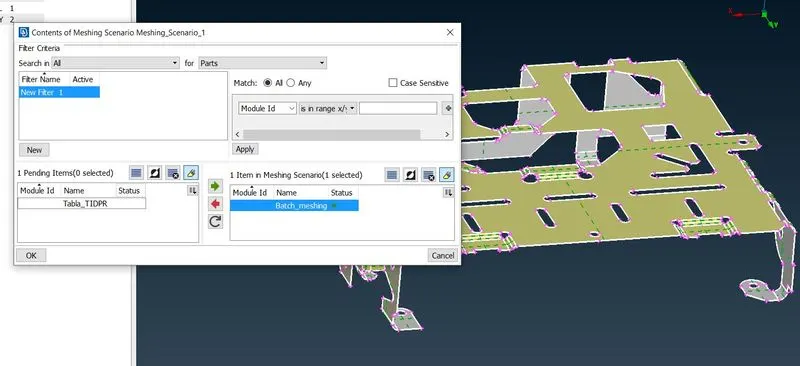
Figure 14: Discretization of component by Batch Meshing method
Now click on “OK” and then need to click on Run option in order to perform batch meshing. Mesh will generate as per quality criteria that we have already assigned. Once mesh will have performed it will look like as shown in picture below:
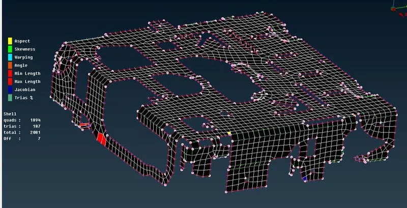
Figure 15: Discretization of component by Batch Meshing method
From above picture we can notice some of elements are failed. In order to rectify such errors, we have to work manually on these failed or off elements and have to recover these errors. Apart from these off elements, batch meshing also have done wrong defeaturing at some of fillet region as shown in picture below.
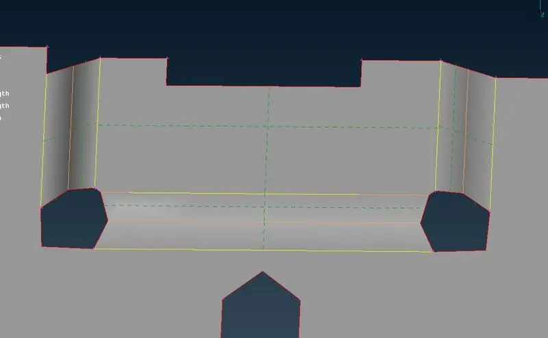
Figure 16: Discretization of component by Batch Meshing method
Now we have to work manually on these features and fix them either by deleting old double CONS and then to add new double CONS in order to capture fillet region accurately. Once some of the regions are captured accurately and then to perform meshing again on these areas. Now, we have no off elements in our model as shown in picture.
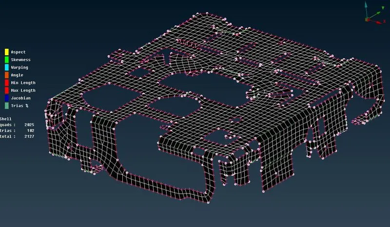
Figure 17: Discretization of component by Batch Meshing method
3.3 Casting Method
3.3.1 Automatic mid surface mesh generating using casting method
Before proceeding to casting method, we have to make sure geometry should be clean. In this method no separate mid surface is required. In order to perform casting method, we have to follow:
TOPO---->Faces---->Mid.surface---->Casting
Then we have to follow some parameters such as minimum thickness, target element length and keep the remaining options as it is. Then Click OK.
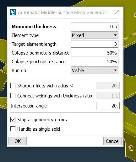
Figure 18: Automatic mid surface mesh generating using casting method
Once automatic middle surface mesh generator is finished, then we will get FE model like as shown in picture
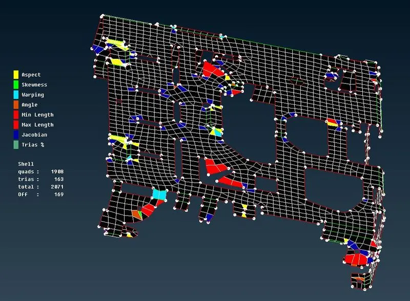
Figure 19: Automatic mid surface mesh generating using casting method
From picture we can analyze, FE model is having lot of issues such as in feature capturing, mesh flow along with quality criteria. In this case, we have FE model alone and it became very hard to capture feature areas without any surface.
Now we have fixed FE model with all issues that we have faced and then we have achieved FE model without any element fails as shown in picture below.
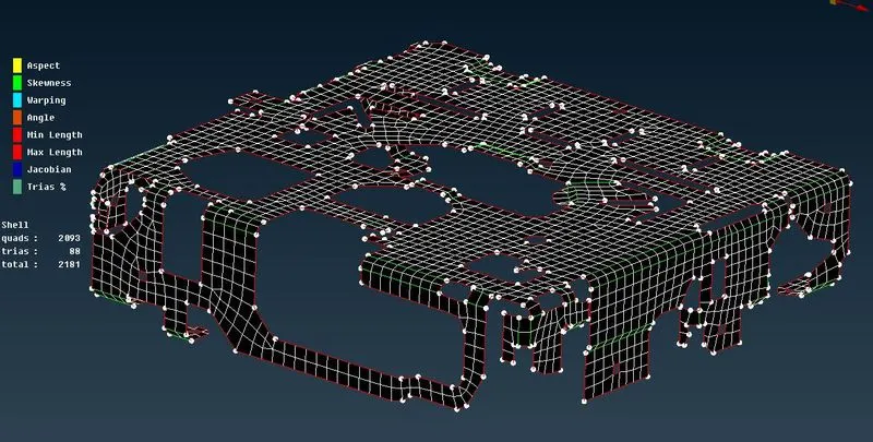
Figure 20: Automatic mid surface mesh generating using casting method
4. Comparison of results
Comparison of results for all meshing methods on same components are as follows:
|
Operations / Methods |
Manual Method |
Batch Meshing Method |
Casting Method |
|
Geometry Cleanup |
Mandatory |
Mandatory |
Mandatory |
|
Middle Extraction Method |
By using offset face method |
By using Mid.surface skin method |
Automatic Middle-Surface mesh generator |
|
Parent Component |
Available |
Not available. Use Undelete option to get parent geometry |
Available |
|
Meshing Method |
Manual meshing, e.g. Spot, Best etc. |
Automatic meshing, e.g. Batch mesh manager |
Automatic meshing, e.g. Automatic Middle-Surface mesh generator |
|
Time taken for complete meshing |
2 to 3 Hours. |
Less than 10min. |
Less than 10min. |
|
Number of Failing elements |
Zero. |
7 |
169 |
|
Time taken for removing element failing |
Zero minutes, because no errors. |
Approx. 4hours |
Approx. 5hours 30 minutes |
|
Number of Quads |
2234 |
2025 |
2093 |
|
Number of Trias |
76 |
102 |
88 |
|
Total number of elements |
2310 |
2127 |
2181 |
Table 1: Comparison of results
LEARNING OUTCOMES
- Preparation of CAD model for casting and batch meshing.
- Improving the mesh flow and quality issue for both casting and batch meshing.
- To rectify the model in complex regions due to defeaturing caused by casting and batch meshing.
CONCLUSIONS
Given sheet metal component is meshed successfully for manual, casting and batch meshing method.
Manual meshing gives good result compare to batch meshing method and casting method. Because manual meshing captures proper features and mesh flow obtained is good. However, it consumes more time to-do meshing. If we have adequate time, then we should prefer manual meshing.
And if we have time constrained to complete given task of preprocessing for given components, then we should go with batch meshing method. Because mid surface extraction is simple and gives off element less compare to casting method.
If no need for quality in less time, then we should prefer either of casting or batch meshing.