PREPROCESSING ON BOTTLE CAP USING ANSA
AIM: To perform preprocessing on components of bottle cap using ANSA Software.
OBJECTIVE:
- To perform Geometry operation on CAD model in order to clean geometrical errors.
- Extraction of mid surface from parent component.
- To set Mesh Parameters and Quality Criteria parameter.
- To perform meshing operation as per quality criteria on mid surface.
- To set Property Identity and thickness.
CAD MODEL:
Import the required file of Bottle Cap model using ANSA software. Once CAD model is open, it will looks as shown in picture below:
After analyzing the model, we have observed bottle cap model is symmetry about Y-axis except few places. So, we will work on half of the model and then rotate it around Y-axis using rotate option under Transform.
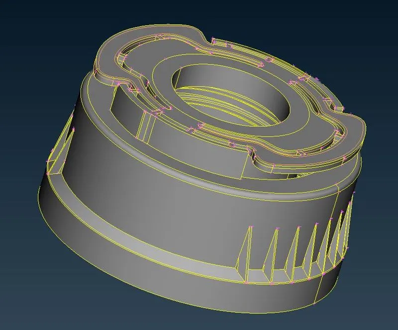
Figure:1 Bottle cap model
PROCEDURE:
1. Geometry Checkup
Before meshing, we have to check the parent geometry in order to eliminate the given errors. Following steps have need to follow for geometrical checkup as follow:
Left click on “Checks” in Tools option Select “Geometry” in options set “Visible” for Execute on (It helps to automatically selecting the visible component in graphical window) Now click on Execute.
Make sure, we have selected all required checks option in templates because error generates will depends upon these selected ANSA Checks option as shown in picture below. Here, in this case Sharp edges and unmeshed macros option are irrelevant. So we will select all checks except these two options.
Also, we have to select Visible option active in “Execute on”.
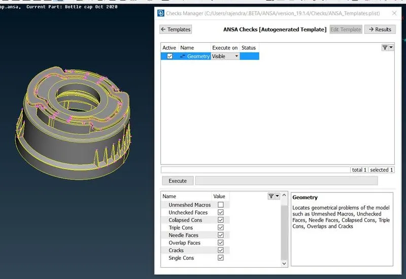
Figure:2 Geometry check for Bottle cap model
To fix all generated errors, we need to right click on all selected visible error and then have to click on fix option.
We can move to next stage only if there are no geometrical error remain.
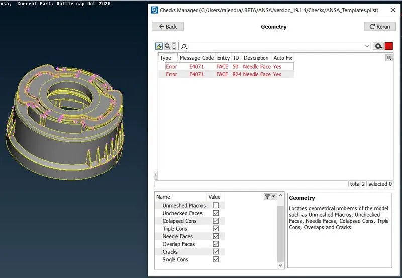
Figure:3 Geometry check for Bottle cap model
After we execute quality check operation for CAD model. Number of errors generated as shown in above picture. To check the exact location of error that where actually it is presented, we have to select show only. Then we will see only that error as shown in below picture.
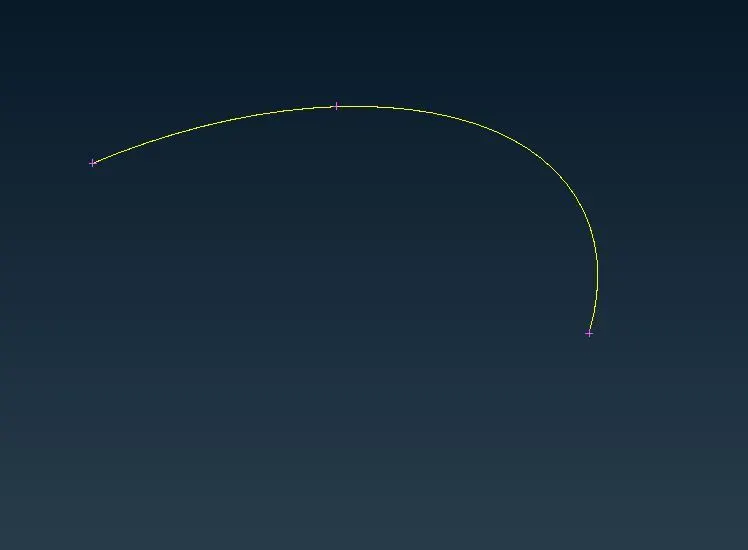
Figure:4 Geometry check for Bottle cap model
In order to rectify generated error, we have two options. Either we can use manual or auto Fix option. We will use auto fix because there is yes mentioned in auto fix. After auto fixing of generated errors ANSA will automatically suppress unrequired CONS and will give error free geometry as shown in picture below.
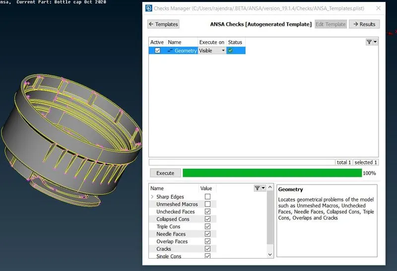
Figure:5 Geometry check for Bottle cap model
To check the accuracy of results, we can rerun the quality check operation again.
2. Mid surface extraction
Mid surface is the surface which lies in middle of bottom & top surface of the parent component. This process takes low storage space and also need low calculating time.
To carry out this operation we have two options. Either we can use auto mid generation or manual mid surface generation.
We are going with manual middle surface extraction because with automatic mid surface generation we will reduce our parent component. In manual mid surface exaction, we will use few common options such as curve middle, face offset etc.
Before taking offset for middle surface, we have to keep different measurements of the component thickness. And then have to make offset at exact middle of object as shown in below picture.
2.1 Symmetry in parent component
From CAD component we have noticed, there is symmetry in component about a plane except few surfaces.
So, we will extract middle surface for half of the portion. Then rotate this half mid surface about 180° around certain COG points using rotate option in Transform.
To divide the geometry in two halves exactly, we have to use “Plane Cut” option under “Faces” in “TOPO” in order to divide geometry exactly as shown in picture below:
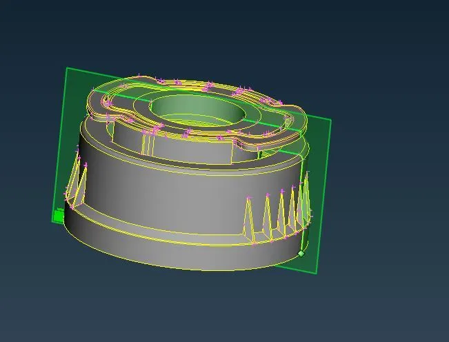
Figure 6: Symmetry in parent component
As CAD model is cut in two halves. One half will looks as shown in picture below:
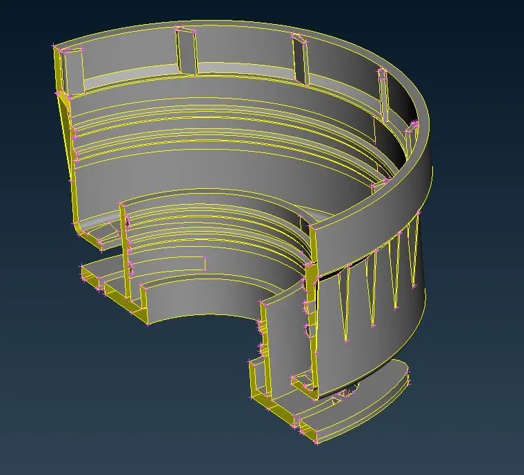
Figure 7: Symmetry in parent component
2.2 MID surface extraction
2.2.1 Face Offset option
Before proceeding to offset operation, make sure to measure thickness appropriately for particular surfaces.
Under “TOPO” module, we have to select “Face Offset”. Selection need appropriate surface to get offset from parent component as shown in picture below:
After which, we have to put value in numbers i.e. offset distance of -0.765mm. Then to confirm offset distance, press middle mouse selection. Then new window get popup, which will ask to set property identity for particular extracted face.
Also, face orientation helps to define direction of mid surface extraction.
SO, by following above mentioned steps. We can extract middle surface for the rest of faces in components.
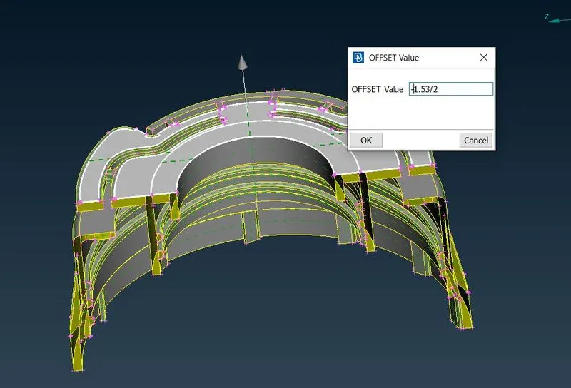
Figure 8: Mid surface extraction
As middle surface is extracted, it will look like as shown in picture below:
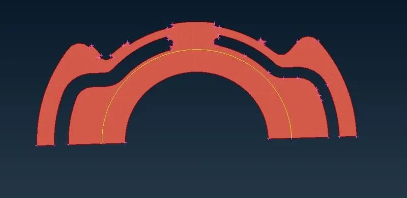
Figure 9: Mid surface extraction
2.2.2 CURVE MIDDLE option
To create curve in middle of two CONS. We have to follow certain steps as mentioned
Under “TOPO” module select “Middle” curve option. After selecting the curves in two groups, by pressing middle mouse button we can confirm our middle curve in particular CONS as shown in picture below:
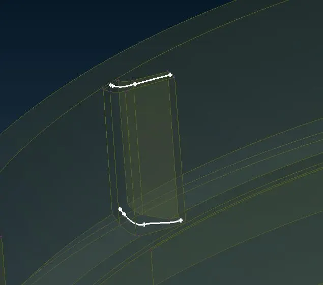
Figure 10: Mid surface extraction
Once middle curves are created, now we have to create new surface using these generated curves. For doing this operation. We need to follow certain steps as mentioned.
Under “TOPO” module, select “NEW FACES”. Once new face is created, we have to extend the face edge to the target surface as shown below
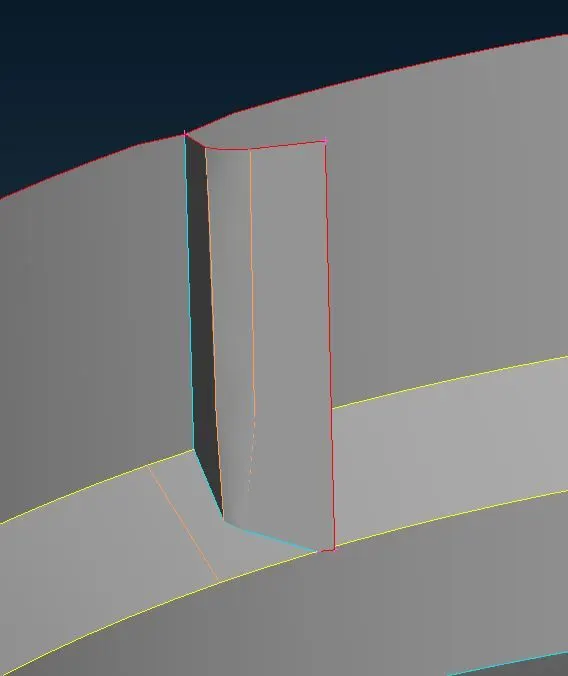
Figure 11: Mid surface extraction
2.3 Half Middle surface
Finally, half of middle surface has been generated as shown in picture below.
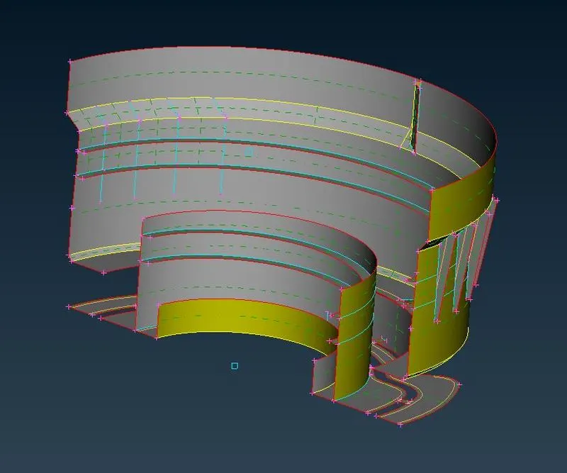
Figure 12: Mid surface extraction
Now, we have to copy and rotate this half of the extracted middle surface about two created COG points around 180°. After done the copy and rotate operation, a full middle surface has been captured as shown in below picture. Then following TOPO operation will help to join two separated middle surfaces.
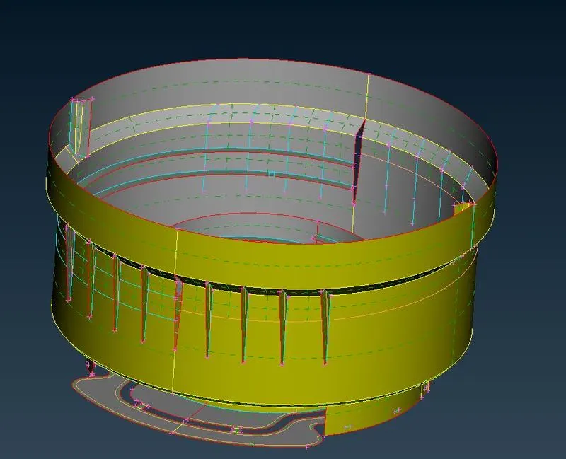
Figure 13: Mid surface extraction
To get pattern feature on the walls of bottle, we will copy and rotate it around certain axis with the help of these two created COG points as shown in picture below:
|
|
|
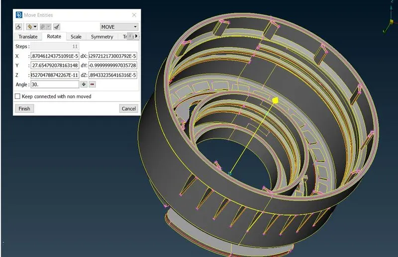
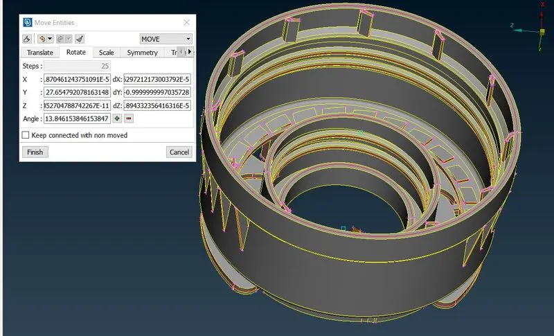
Figure 14: Mid surface extraction
So, finally full middle surface will look like as shown in picture below:
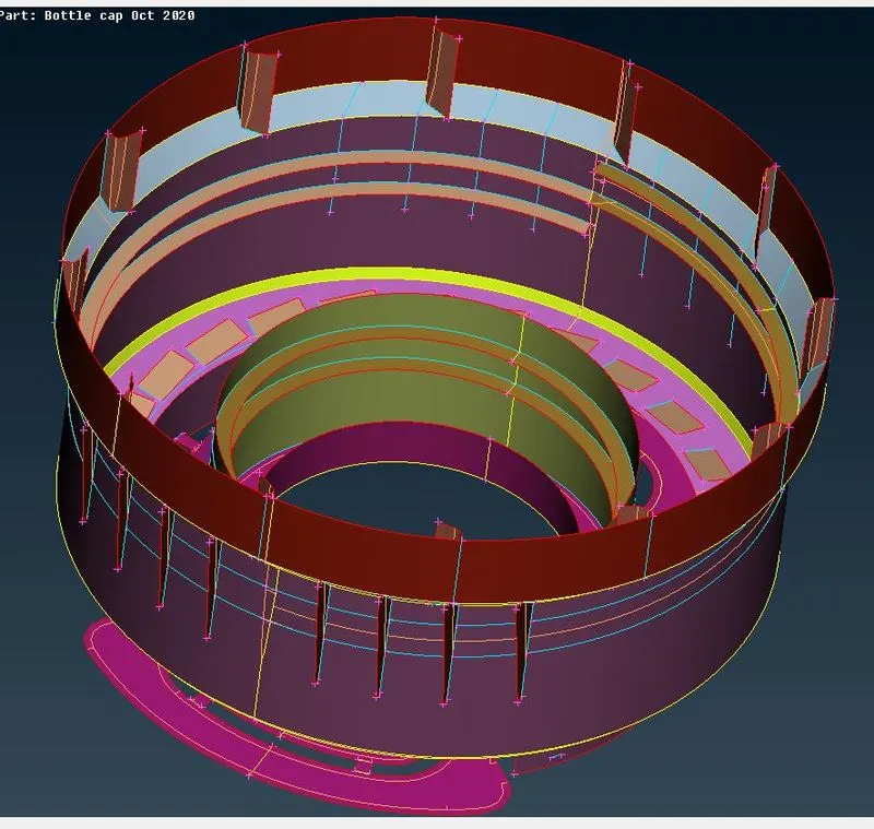
Figure 15: Mid surface extraction
3. Mesh Parameters and quality criteria
Now we have to give different mesh parameters such as average Target length, maximum & minimum target length. According to these parameters our mesh model will get discretize.
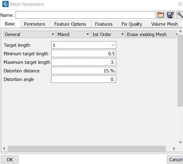
Figure 16: Mesh Parameters
After assigning mesh parameters we have to assign Quality criteria presentation parameters. Quality criteria helps to make understand whether our finite element model will fail or not.
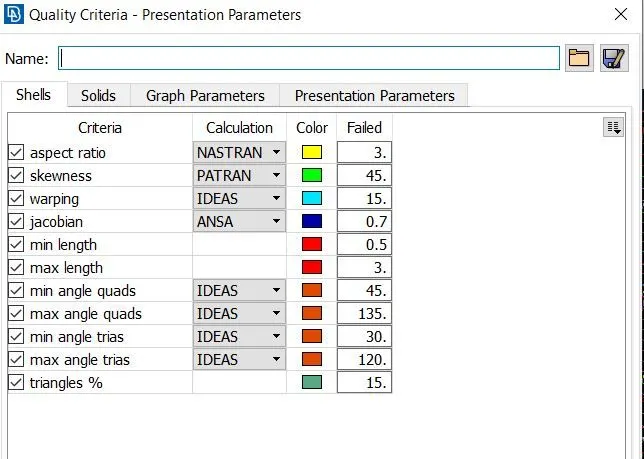
Figure 17: Quality criteria - Presentation Parameters
4. To perform shell meshing
A mesh is a network that is formed of cells and points. A meshing is the process of subdividing the structure from infinite number of points to the finite number of node and elements. This process is also known as discretization.
In ANSA, we have variety of options to perform meshing. Now, we will use “BEST” option for meshing to generate FE elements on each and every surface of model.
During meshing we have to take care of quality criteria. Because on click of meshing option, it will generate improper meshing. So we have to improve meshing pattern in order to satisfy the quality criteria.
Meshing has been performed using BEST mesh algorithm. Using reconstruct function in shell mesh, we have achieved high quality shell mesh. To achieve the overall quality, reconstruct function examine the current mesh and performs re-meshing in order to optimize the overall quality of mesh.
After performing meshing on Bottle cap, component will look like as shown in picture
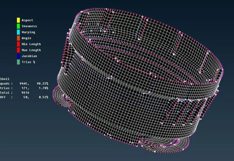
Figure 18: Mesh on Bottle cap model
In this case, after meshing few elements are failed due to of triple CONS. These are unavoidable.
SHELL AS SOLID
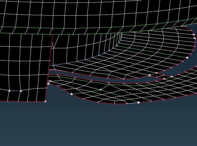
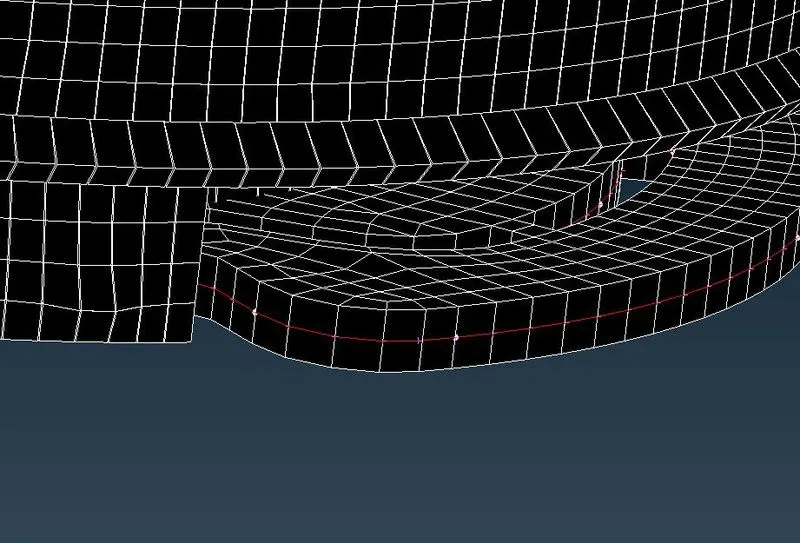
In order to assign thickness, we have to make sure our thickness value should be in property identity. So to activate thickness at final stage, we have to check draw shell as solid under presentation parameters.
 |
 |
|
Without Thickness |
With Thickness |
Figure 19: Shell as solid
Learning Outcomes
- Able to fix topological error.
- Able to do middle surface extraction.
- Creating of Mid surface using offset, Middle, Middle{curves} and Middle{Multi}.
- Aware with importance of quad and tria elements in shell meshing.
- Aware with the meaning of quality criteria parameters.
- Good in achieving better mesh flow, even in complex problems.
CONCLUSION
So, preprocessing is done successfully on given component i.e. Bottle Cap model like geometry checkup, mid surface extraction which is followed by meshing operation and then assigning thickness to middle surface.
Therefore, percentage of trias obtained in overall meshing is 1.78%.
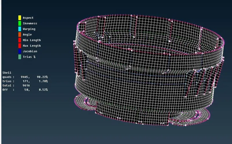
Figure 20: Mesh on Bottle cap model