PREPROCESSING OF REAR VIEW MIRROR MODEL USING ANSA
AIM: To perform preprocessing on components of rear view mirror model using ANSA Software.
OBJECTIVE:
- To perform geometry cleanup on different component of car rear view mirror model.
- Assigning mesh parameters and quality criteria parameter for 2D and 3D elements.
- To perform shell meshing on different components as per given quality criteria.
- To perform volumetric meshing after defined the closed volume in the model
- To perform tetrahedral meshing on different components as per quality criteria.
CAD MODEL:
First, we have to Import the required file i.e. Rearview mirror in ANSA software by using GUI option. Once model is open, it will look in graphical window as shown in image below:
Rear view model consist of four different components i.e.
- Handle,
- Spherical bearing,
- Mirror and
- Mirror Frame
|
1. Handle |
2. Spherical bearing |
|
3. Mirror |
4. Mirror Frame |
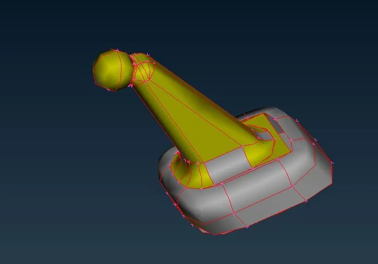
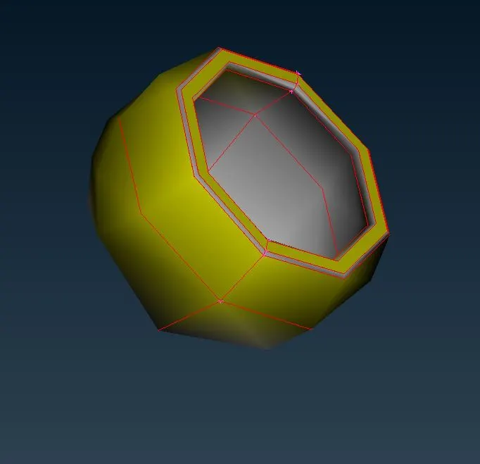
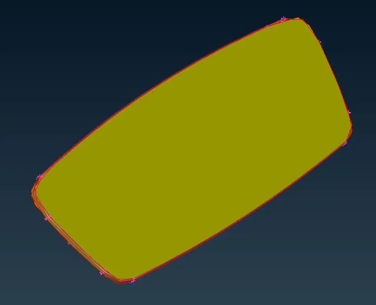
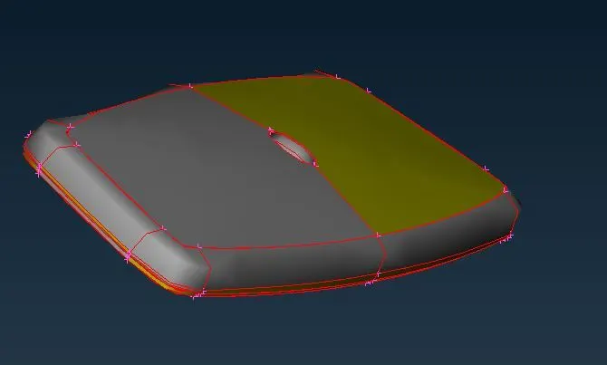
Figure 1: Components of Rear view mirror Model
PROCEDURE:
1. Geometry cleanup on different component of Rear view mirror model
(1) Topology Cleanup
After opening the given model, we have analyzed given CONS are not connected to each other (as shown in red color). So in order to connect these CONS, we need to perform topology operation using certain steps i.e. TOPO Faces Topo in a single box selection of components.
After done the topology cleanup, model will look like as shown in picture below.
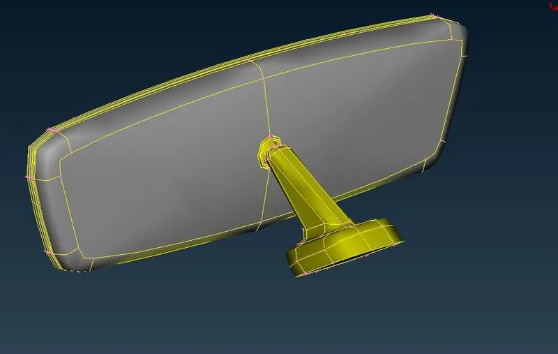
Figure 2: Topology cleanup
(2) Geometry Checkup
Before proceeding to meshing, we have to make sure that geometry is free from errors.
Ansa is having default template, where we have to filter our model for given errors. In this case, we have to select all except Sharp edges and unmeshed macros.
In order to check the geometry for errors, following steps have to follow for geometry checkup:
Left click on “Checks” in Tools option Select “Geometry” in options set “Visible” for Execute on (It helps to automatically selecting the visible component in graphical window Now click on Execute.
Error shown will depends on selected ANSA Checks option in template as shown in picture below.
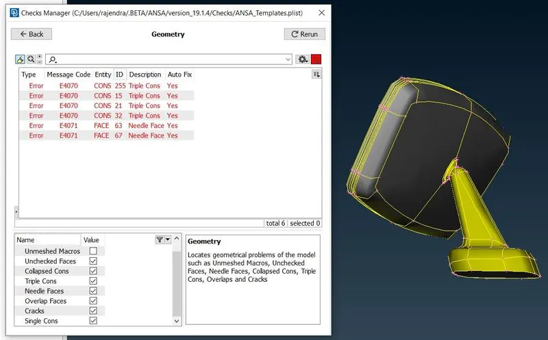
Figure 3: Geometry check
In order to check any particular error, right click on that error and select show only. It helps to identify particular error location in the component. In order to fix these error, we have two options. Either we can use manual or auto Fix. We will use auto fix because we noticed yes for Auto Fix in ANSA template, that means ANSA can fix these errors automatically.
we can move to next stage only if there are no geometrical error remains. So we will rerun the geometry checkup macro and check the model for results as shown in picture below:
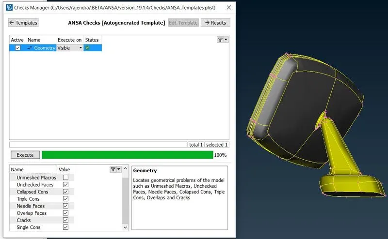
Figure 4: Geometry check
Now geometry is free from errors. So we can proceed to further steps.
2. Mesh Parameters and quality criteria
Before proceed to meshing, we have to assign different mesh parameters such as average Target length, minimum and maximum target length. And we have to keep element type is “Ortho Tria”. According to these parameters our mesh model will get discretize.
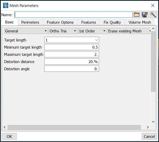
Figure 5: Mesh Parameters
After assigning mesh parameters we have to assign Quality criteria presentation parameters. Quality criteria helps to make understand whether our finite element model will fail or not. For 2D elements we will take care of minimum and maximum length only.
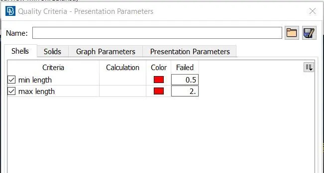
Figure 6: 2D element Quality criteria - Presentation Parameters
For 3D Tetra elements in case of volume meshing, we will take care of Tet Collapse quality criteria only.
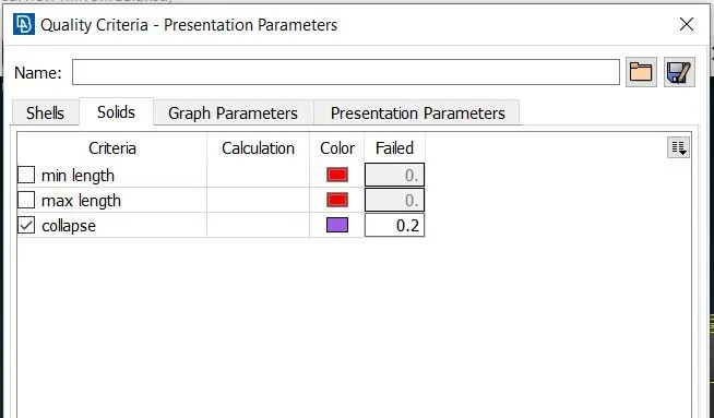
Figure 7: 3D element Quality criteria - Presentation Parameters
3. To perform shell meshing
A mesh is a network that is formed of cells and points. A meshing is the process of subdividing the structure from infinite number of points to the finite number of node and elements. This process is also known as discretization.
And we have to maintain the distance between two nodes equal to the average target length i.e. 1mm. This can be done by following certain steps i.e. MESH Perimeters Length for both Perimeters and Macros.
Before meshing we have to check topology cleanup requirement of components in model.
In ANSA, we have variety of options to perform meshing. Now, we will use “BEST” or “SPOT” option for meshing to generate FE elements on each and every surface of model.
And we will use only TRIA and ORTHO TRIA elements for meshing. Ortho Tria should be used in curved surfaces. Ortho Tria captures the feature more accurately then normal Tria. Quality with capturing ortho Tria is more accurately.
During meshing we have to take care of quality criteria. Because on click of meshing option, it will generate improper meshing. So we have to improve meshing in order to satisfy the quality criteria.
3.1 HANDLE
Before topology cleanup:
As shown in picture below, few double CONS are very nearer to each other. Which will surely fail for minimum length criteria while performing meshing.
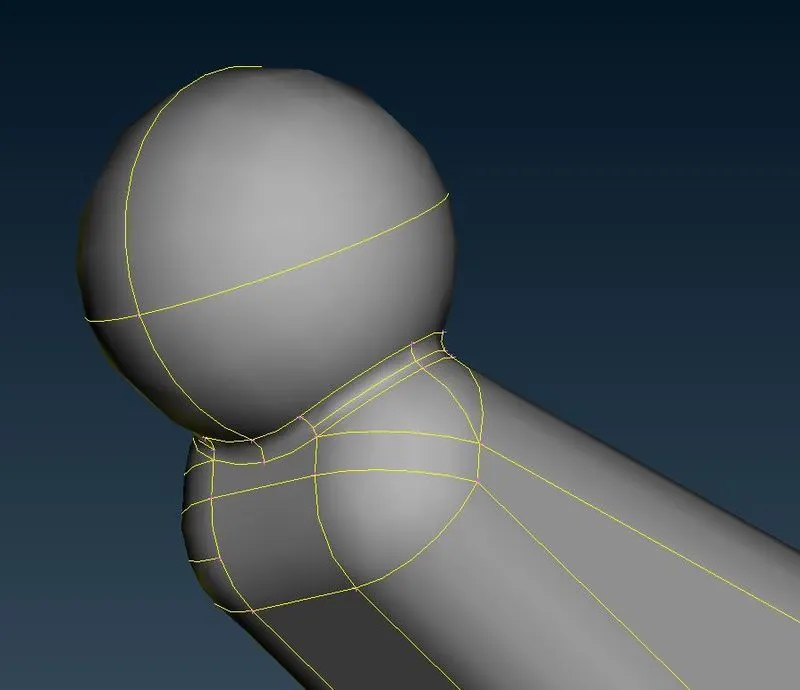
Figure 8: Topology cleanup Handle
After topology cleanup:
Such case of failure can be avoiding by suppressing appropriate CONS as shown in picture below.
Now, if we perform meshing on this region, element will satisfy quality criteria. And we will get proper mesh flow.
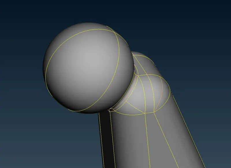
Figure 9: Topology cleanup Handle
SHELL MESH
As topology cleanup is finished according to required areas. Now we have to perform shell meshing surface by surface as per quality criteria.
To achieve the overall quality, reconstruct function examine the current mesh and performs re-meshing in order to optimize the overall quality of mesh.
After performing meshing on handle, it looks like as shown in picture below
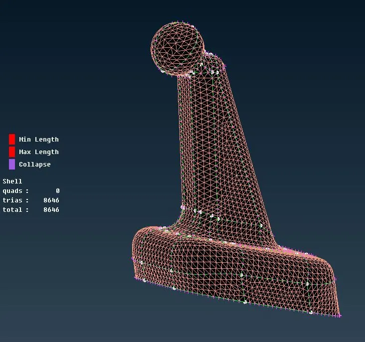
Figure 10: Shell mesh Handle
3.2 SPHERICAL BEARING
Before topology cleanup:
Before Topo cleanup, distance between two CONS on fillet region as shown below is very less. If we keep these double CONS and will perform shell meshing. Then most probably, meshing will get fail due to minimum length parameter in quality criteria.
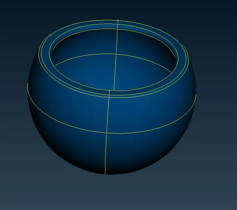
Figure 11: Topology cleanup Spherical Bearing
After topology cleanup:
In order to avoid such failure of quality issues, the unwanted CONS are suppressed using CUT and JOIN function in Macros. To generate middle double CONs on flat surface, we use Middle function in Curves. Once Middle curve is generated then we will use Project function in CONS under Topo to project the curve on face. And resultant component will look like as shown in picture below:
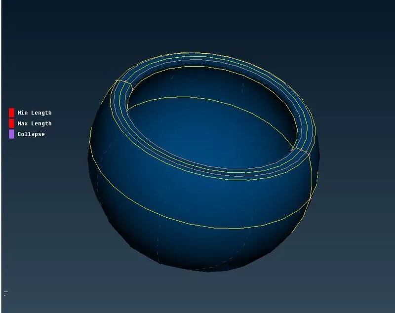
Figure 12: Topology cleanup Spherical Bearing
SHELL MESH
As we know, we can start meshing only if geometry cleanup is correctly done for entire component. Using BEST or SPOT function in mesh operation, mesh is done by selecting element type Ortho Tria in option list for better quality and quality criteria is satisfied as shown in picture below.
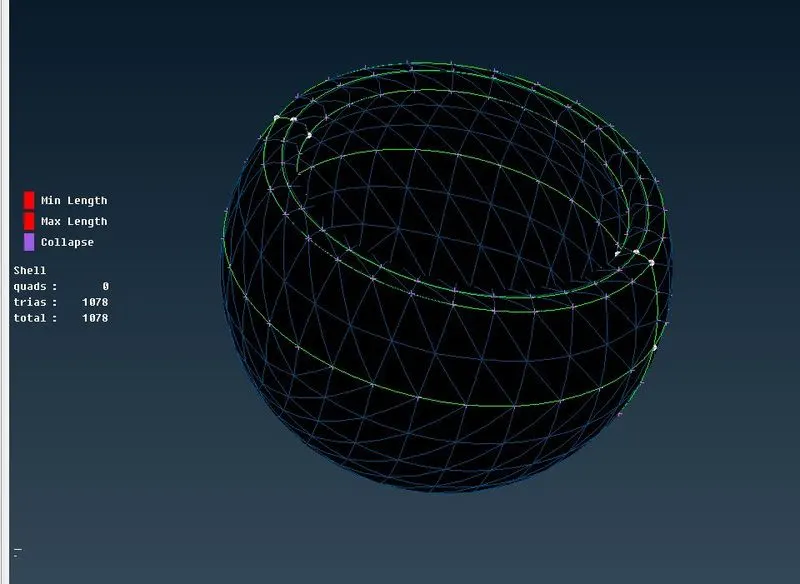
Figure 13: Shell mesh Spherical Bearing
3.3 MIRROR
For this component, we have no need to perform topology cleanup. So, we can directly approach to meshing.
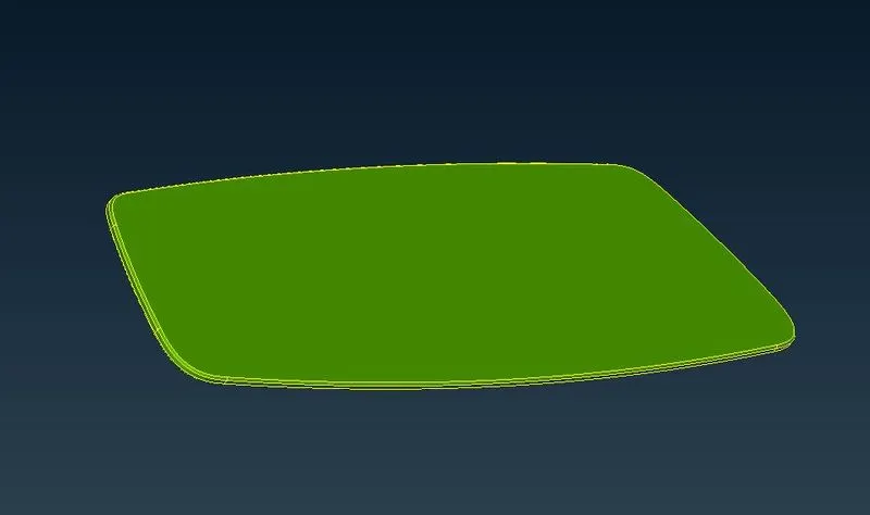
Figure 14: Topology cleanup Mirror
SHELL MESH
In order to capture proper mesh flow, we will perform mesh operation on this component surface by surface by considering quality criteria parameters as shown in picture below
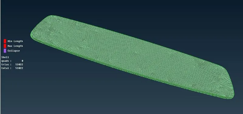
Figure 15: Shell mesh Mirror
3.4 Mirror Frame
Before topology cleanup
Without geometry cleanup, again double cons in component are very nearer to each other. So need to suppress one of them. Now before cleanup is looking as shown in picture below
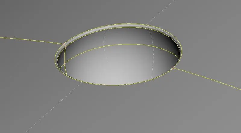
Figure 16: Topology cleanup Mirror Frame
Similarly, double cons are found nearer to each other on side edges of frame as shown in picture below
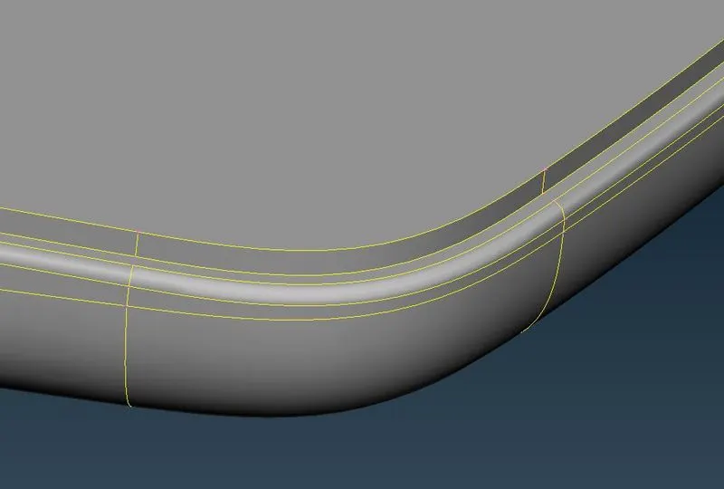
Figure 17: Topology cleanup Mirror Frame
After topology cleanup
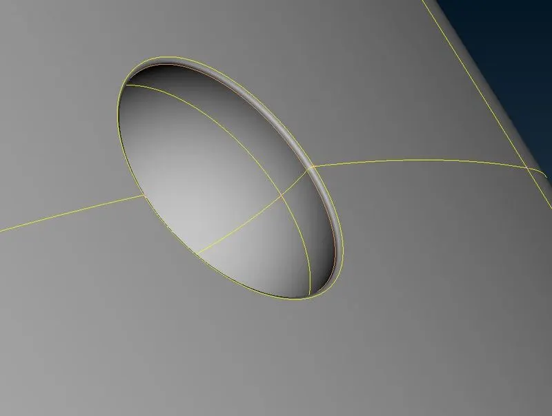
Similarly, we have to suppress unnecessary double cons. So that we can rectify minimum length criteria element issue. So, after geometry cleanup component looks as shown in picture below
 |
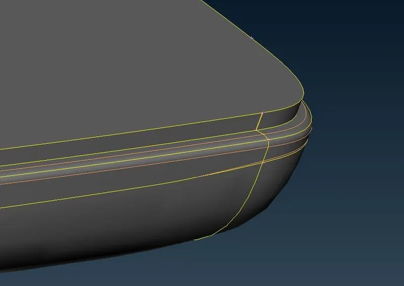 |
Figure 18: Topology cleanup Mirror Frame
SHELL Mesh
Using BEST or SPOT mesh function, we perform mesh operation on this component. Now, if elements are not proper then we have to reconstruct the mesh flow. This process will continue until we get proper mesh flow. So, Mesh flow will look like as shown in picture below:
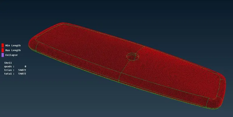
Figure 19: Shell mesh Mirror Frame
4. CONTORL VOLUME
Before proceeding to volume meshing. We have to assign volume for the geometry in the option list as shown in picture below. While doing 2D meshing, we have to make sure there should be no opening.
For 3D meshing, we will use element type Tetra rapid for two of the component in model and Tetra FEM for remaining two components.
To create this list, in “Volume Mesh” module we have to select “Manual” option in defines under “VOLUMES” and have to use box selection for selecting certain component.
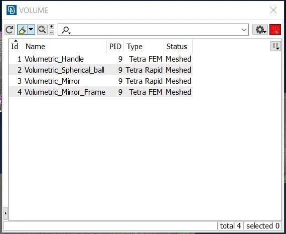
Figure 20: Control volume list
5. TETRAHEDRAL MESHING
5.1 HANDLE
To perform tetrahedral meshing on handle, we will use algorithm type Tetra FEM to generate meshing in interior of volume as shown in picture below.
Also we have to make sure, there should be no kinks and dips on the surface of components. If we get any collapse, we have to rectify those elements by moving nodes manually. Some of the methods that can helps use for improving the quality of elements are as follow:
- Manual adjustment
- Drag node
- Auto quality improvement
So, we have no TET collapse issues in this component.
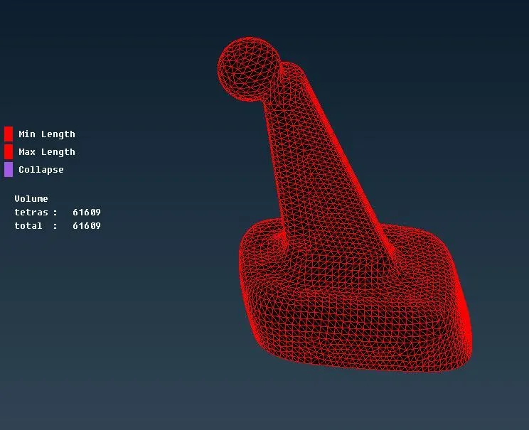
Figure 21: Solid mesh Handle
As we will take sectional view for this component. It looks like structure shape of meshing element near the face is maintained good and get lost as proceed away form face.
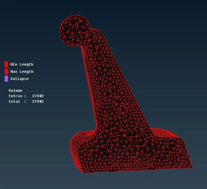
Figure 22: Solid mesh Handle
5.2 SPHERICAL BEARING
In this case, we will use Tetra rapid algorithm to generate tetrahedral element. After volumetric meshing we have no Tet collapse issue as shown in picture
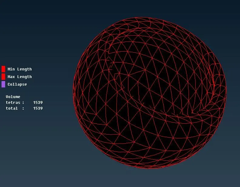
Figure 23: Solid mesh Spherical Bearing
And here is a section view for spherical bearing as shown
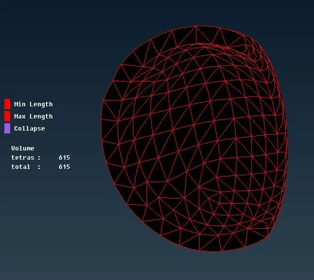
Figure 24: Solid mesh Spherical Bearing
5.3 MIRROR
Similarly, tetrahedral meshing is done using Tetra rapid algorithm on this component with no Tet collapse issues as shown in picture
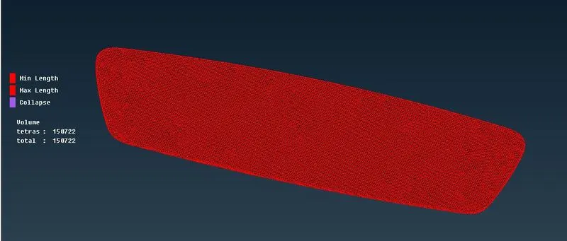
Figure 25: Solid mesh Mirror
And sectional view for this component as shown in picture
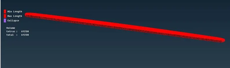
Figure 26: Solid mesh Mirror
5.4 Mirror Frame
Now we will use Tetra FEM algorithm to generate tetrahedral element on mirror frame model. After performing 3D meshing, we found meshing with zero or no Tet collapse issues as shown in attached picture.
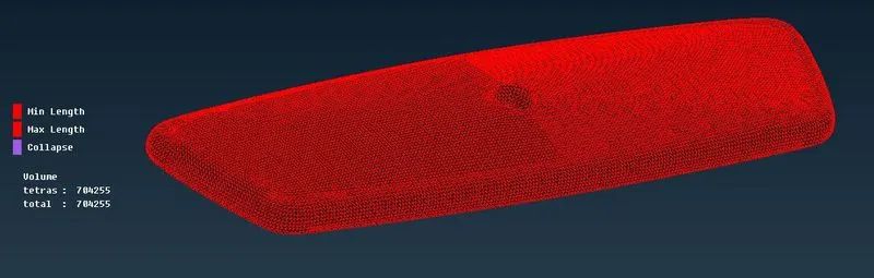
Figure 27: Solid mesh Mirror Frame
And sectional view for this component looks like as shown in picture
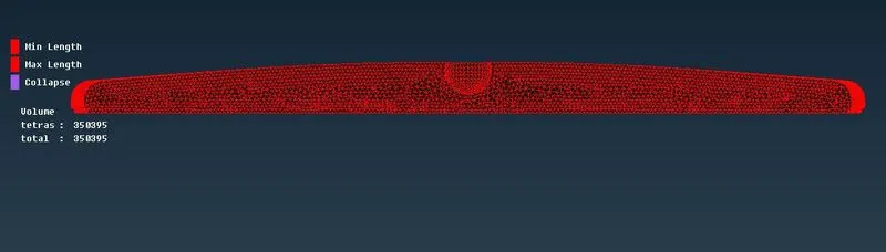
Figure 28: Solid mesh Mirror Frame
Learning Outcomes
- 3D meshing on solid object.
- Learnt how to fix quality issues in 3D meshing
- Aware with different types of algorithm in volume generation.
- Aware with the use of Ortho Tria elements on curved surfaces.
CONCLUSION
So, preprocessing is done successfully on given components of rearview mirror model such as geometry checkup, shell meshing using Trias and Ortho Trias, quality checking for 2D meshing, defining control volume, generating tetrahedral volume meshing using different algorithms with no compromise of quality issues.
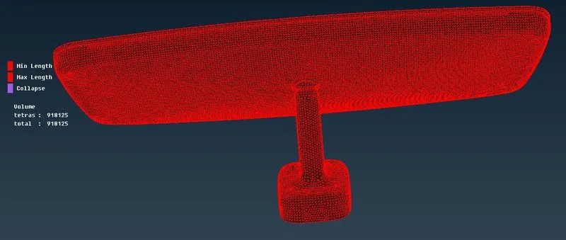
Figure 29: Mesh on rear view Mirror model