CREATING CONNECTIONS FOR REAR DOOR USING ANSA
AIM: To create connections for rear door of car using ANSA Software.
OBJECTIVE:
- To assign property identity for every subpart.
- To create RBE2 Element in order to represent bolt connection.
- To create RBE3 Hexa RBE3 element in order to represent spot weld connection.
- To create RBE3 CBUSH RBE3 element in order to represent weather strips.
- To create seam weld connection.
- To create mass concentration element in order to represent door handle.
CAD MODEL:
First, we have to Import the required file i.e. Side Door in ANSA software by using GUI option. Once rear door model is open, model looks like as shown in picture below:
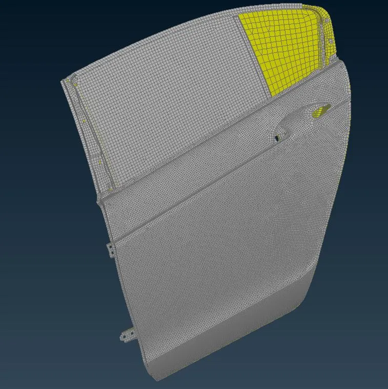
Figure 1: Rear Door CAD Model
PROCEDURE:
1. Assigning property identity card
After opening the given model, now model is in entity mode. So, for visualization purpose we will shift mode from entity(ENT) to property identity mode(PID). As we shifted to PID mode, we have noticed that whole model is in single PID card as shown in picture below. If whole model will be in single PID, then we could not single different parts for connection.
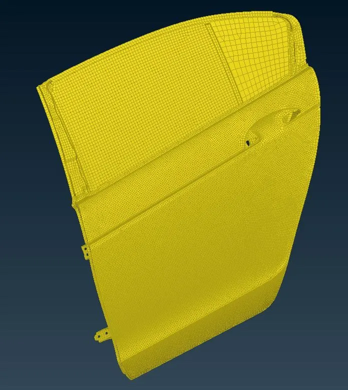
Figure 2: Assigning property identity card
So to avoid such issues, we have to segregate the parts from group and have to assign different PID to different component of similar groups. So, once PID is assigned. Model will looks as shown in picture below.
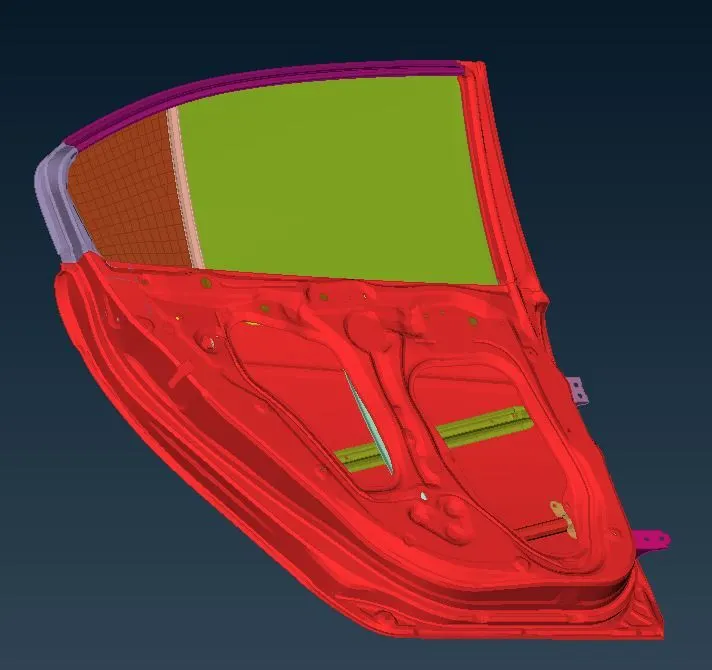
Figure 3: Assigning property identity card
2. Creating various connections:
There are number of connections available. So we will discuss and deploy different connections one by one wherever we have to use.
2.1 Rigid Body Element (RBE2):
As name suggests, RBE2 is a type of element which makes connection rigid and prevents movements along translation and rotational in x, y and z axis. We have two type of RBE2 connections to use i.e. many node RBE2 and two node RBE2.
In order to create RBE2 Connection, we have to follow NASTRAN Deck---->ELEMENTs---->RBE2
We will create RBE2 element connection using two methods i.e. Cluster method and 3D bolt point.
2.1.1 Cluster method:
This type of connections is created between two or more holes using the same command as mentioned above.
First of all, we have to select slave nodes (nodes which are on the perimeter of holes) slave nodes are dependent nodes. Then by clicking middle mouse button master note will select automatically which is independent node. And then RBE2 cluster will form. This method is having multiple number of dependent nodes and one independent node. After assigning this method, connection will look like as shown in picture below
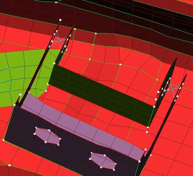
Figure 4: Cluster method
2.1.2 3D bolt point method
To create 3D bolt connection, first we have to create COG point on the circle of hole. Then we have to use convert function in assembly module, which will help to convert point into bolt.
After this we have to select connection manager, and then window will pop-up i.e. for connection selection assistant. Where we have to select the bolt for which we have to make connection and then with the middle mouse click new connection manager tab will open.
Now we have to select three different parts which are going to make final connection by using RBE2 elements.
We have to select FE representation type i.e. Bolt, and then we have to enter search distance which we have to maintain more than the actual distance between parts. And have to maintain possible degree of freedom. Then click on apply and realize it. Once connection is established, it will look like as shown in picture below.
For this connection we have multiple number of slave nodes and one master node for each part and these master nodes are interconnected by two node RBE2 with constraint all degree of freedoms. To represent these connection, we have different zones selection as shown below.
|
a. Zones: In/Out |
b. Zones: Inner |
|
c. Zones: In/Out X |
d. Zones: Outer |
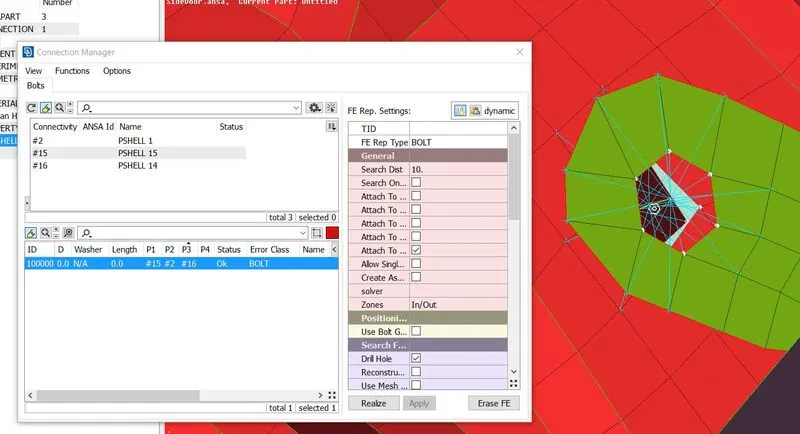
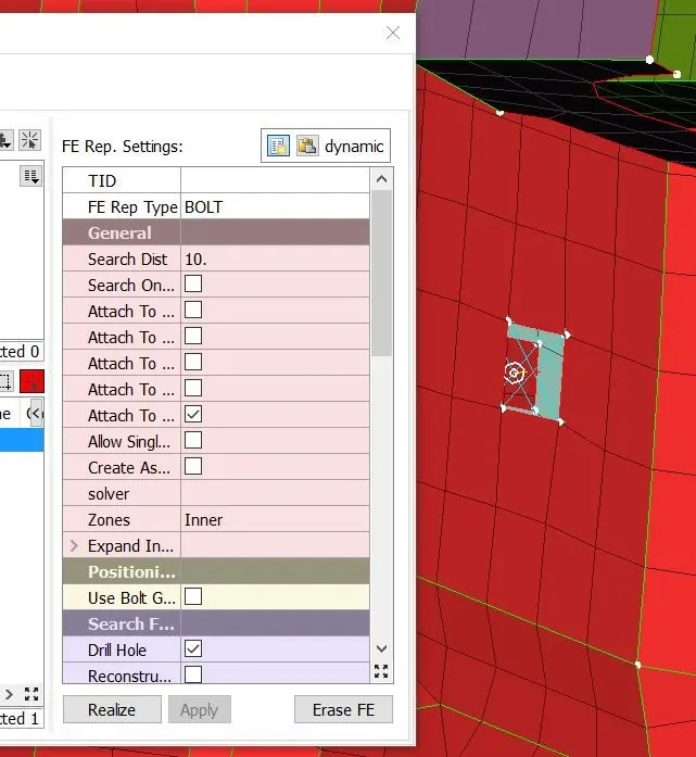
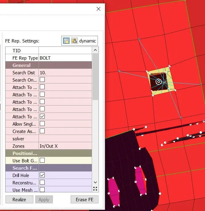
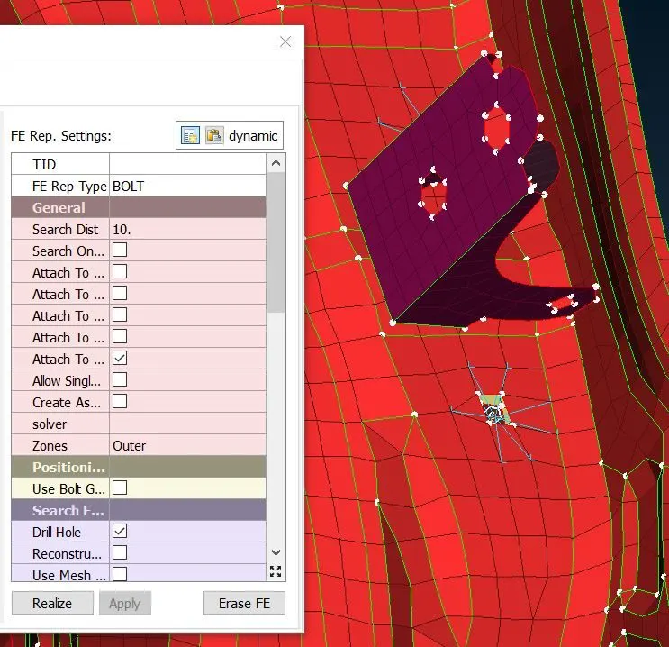
Figure 5: 3D bolt point method
To make the hinge connection, first we have to create cluster RBE2 on both side of hinges. Now by using RBE 2 two node method, rotating link will create between master node of cluster RBE2. As we can observe from global axis, rear door has to rotate about z-axis. So, we will constrain all degree of freedom except rotational movement about z-axis. This constraining is possible by assigning 12345 in CM parameter as shown in picture below. Now rear door is free to rotate around z-axis.
Now similar process can be achieved for lower hinge by following above mentioned steps.
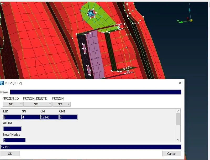
Figure 6: 3D bolt point method
2.2 Creating Seam weld connection
Seam weld connection is also used to connect two mating parts. Generally, we use two types of seam weld connection i.e. overlap shell and Y-joint shell. Overlap shell connection is used when we have to connect two parts which are parallel to each other. And Y-joint shell is used when we have to connect two parts which are perpendicular to each other.
Here, in this case we will use overlap shell weld connection. Steps to create connection are as follow:
Mesh module ----> Perimeter----> Feat2curv. This command will help to create curve from the CONs.
Now we have to convert the curve into seam line. Then using connection manager, we have to select overlap shell in FE representation type. Now overlap shell weld connection is established between parallel mating parts by selecting appropriate sheets in P1 and P2 as shown in picture below.
On other side of this tube we can establish similar connection by following above mentioned steps.
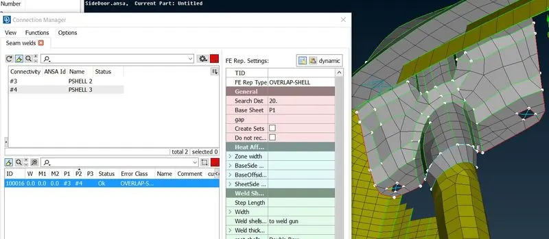
Figure 7: Creating Seam weld connection
2.3 Creating RBE3-CBUSH-RBE3 Elements
RBE3-CBUSH-RBE3 connection helps to establish connection in between mirror and the door panel. These connections are also known as weather strips connection. These weather strips play an important role to maintain climatic condition in between the outside and inside air.
To establish this connection, we have to follow following steps
Hide all components of rear door FE model except both glasses as shown in picture below
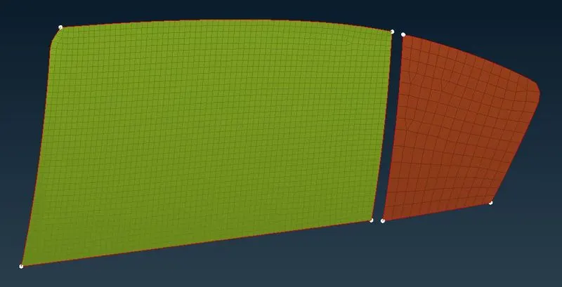
Figure 8: Creating RBE3-CBUSH-RBE3 Elements
Now we have to extract curve from the edges of glasses using Feat2curv.
After this, we have to convert the curve into spot line using convert command in assembly.
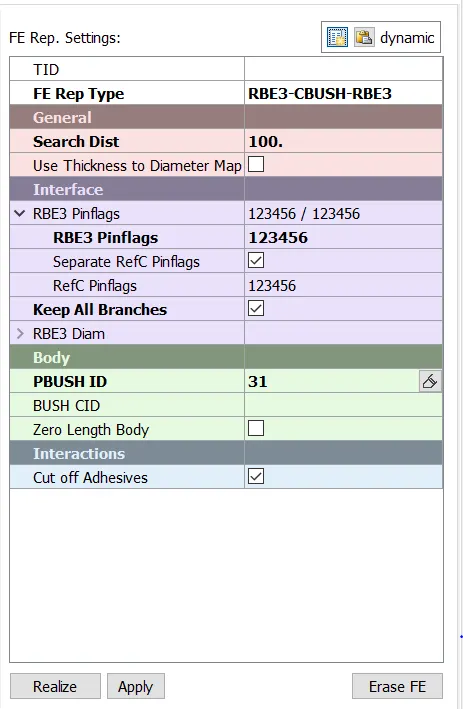
Now click on connection manager in assembly, select the created spot line. Now we have to enter space distance 10, select P1 and P2 appropriately and FE representation type will be RBE3-CBUSH-RBE3 as shown in picture below. Then click on apply and realize the connection.
 |
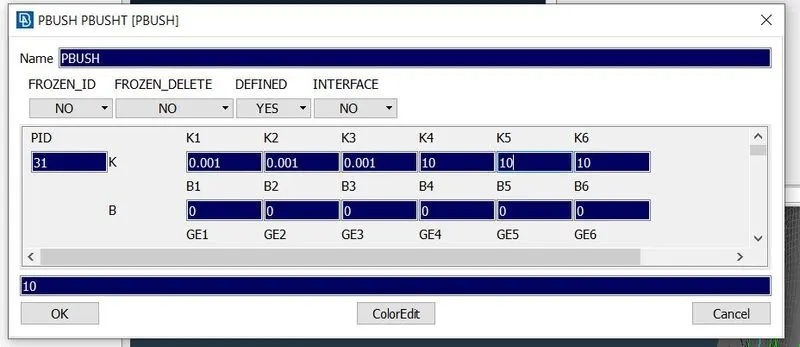 |
Figure 9: Creating RBE3-CBUSH-RBE3 Elements
After realizing the connection, RBE3 CBUSH RBE3 connection is established as shown in picture below.
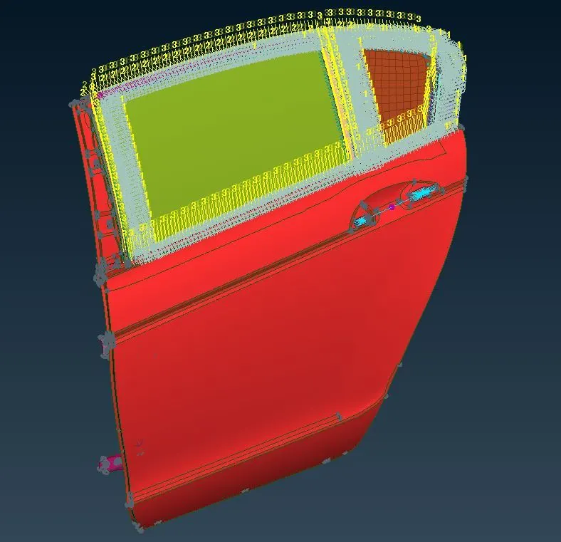
Figure 10: Creating RBE3-CBUSH-RBE3 Elements
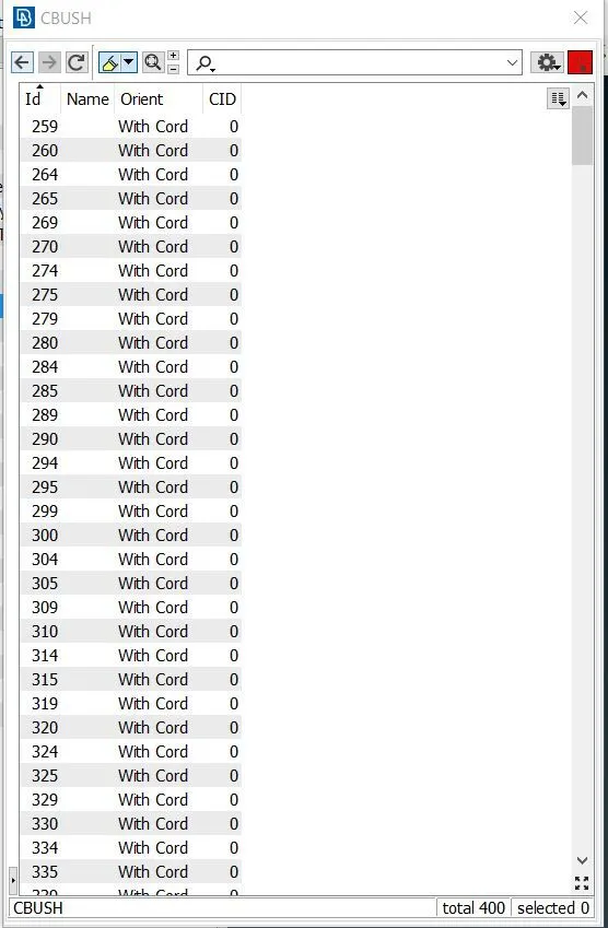
We have to make sure local coordinates should be aligning with the global coordinates. If not, then we have to change the orientation of the element from local to global coordinate system.
 |
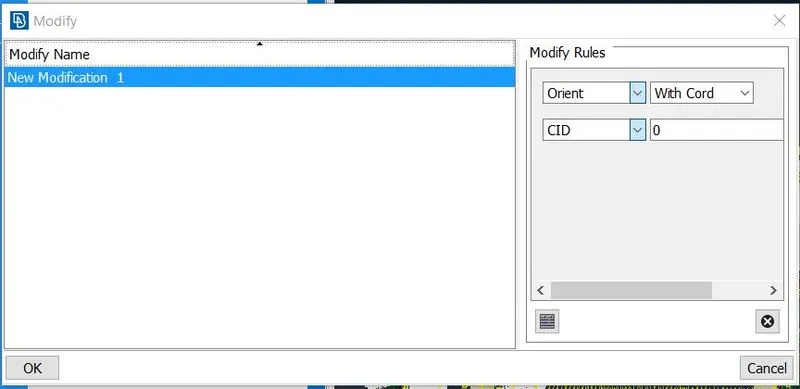 |
Figure 11: Creating RBE3-CBUSH-RBE3 Elements
2.6 Creating RBE3-HEXA-RBE3 elements
To establish RBE3-HEXA-RBE3 connection, first we have to create COG point at the surface of the plate.
Then covert the COG point to spot weld point.
Then use the connection manager, select spot weld point and press middle mouse button. Then window will pop-up. In P1 and P2 we have to select parts which are going to establish connection. FE representation distance will be RBE3-Hexa-RBE3 connection. Provide the search distance between mating parts, generally which distance is more the actual distance. And all degree of freedom will be constrained. Then click on apply and realize. And finally connection will form and it will looks like as shown in picture below.
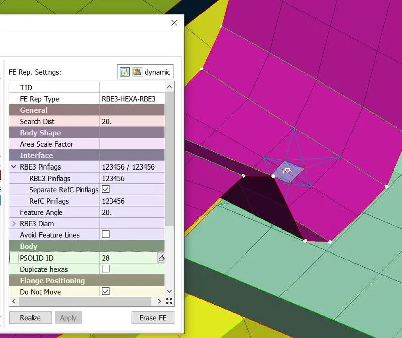
Figure 12: Creating RBE3-HEXA-RBE3 elements
2.7 Creating concentrated mass element connection
While modelling for simulation, when we get any mechanism such as handle, motor etc. presented in the system. Then to show such mechanisms we will use concentrated mass element connection.
Following steps are need to follow to establish this connection. First we have to use RBE2 many nodes to create multiple slave node and single master note. This operation has to repeat for both slots of handle.
Now we have two master node, one at each slot. Again we have to use RBE2 node to make one master node for previously created master nodes. Now this master node will act as a COG point for both the slot of handle. Which means all load of handle will assume to act at this COG point.
In order to assign mass at COG point, we have to follow
Nastran deck---->Elements---->CONMi---->CONM2---->Nodes----> select new created master node
Once COG point is selected and then press middle mouse button. Then new window get popup, where we have to assign mass (in tons) as shown in picture below.
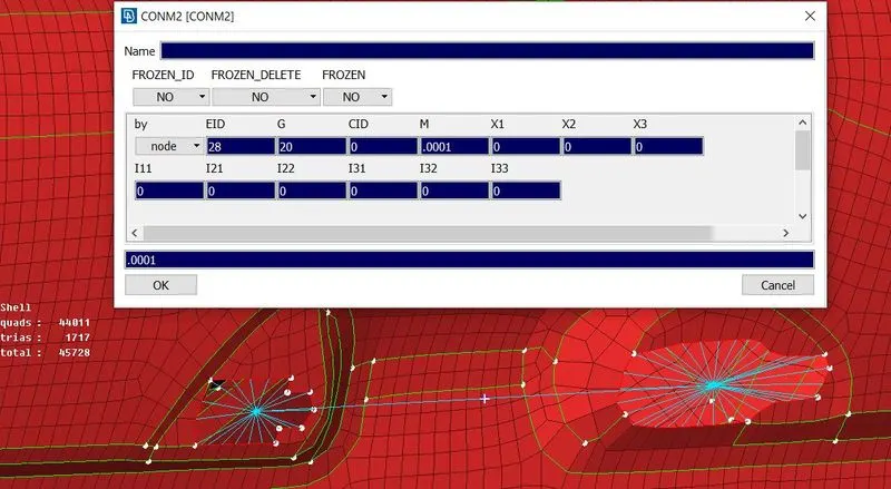
Figure 13: Creating concentrated mass element connection
Press ok. Now, mass is defined at the node.
Learning outcome
- 1D element and type of connection.
- Different type of methods to make connection.
- Assigning mass to the body.
- Assigning seam and spot weld connection.
CONCLUSION
So, connections are created successfully for given rear door model of a car by using RBE2, RBE3-HEXA-RBE3, RBE3-CBUSH-RBE3 and CONMi element.